Week -2
(1) AIM : To simulate the model of door bell using solenoid with the following parameters.
INTRODUCTION :
SOLENOID : A Solenoid is a type of ELECTRO MAGNET the purpose of which is to generate controlled magnetic field through a coil wound in to a tightly packed helix
The coil can be arranged to produce a uniform magnetic field in a volume of space when an electric current is passed through it.
The term solenoid was coined in 1823 by ANDREW MARIE AMPERE to designate a helical coil.
The basic components used to setup a simple doorbell circuit are
BATTERY, SWITCH, SOLENOID, A BELL WITH A PLUNGER.
PROCEDURE :
Solenoid block and battery block are taken. These are connected with positive and negative terminals
Switch block is used between the solenoid block and battery block
To operate the switch we must provide a physical signal through ps-port in the switch block
The provided physical signal must be greater than the threshold of the switch for the switch to be closed or else it will be opened.
Now the whole battery, switch and solenoid path is connected to electrical reference block which represents the earthing of the circuit.
The electrical reference block should be connected with negative terminal of battery block.
In the solenoid block R and C are two variables which represent the plunger and fixed point respectively.
R is connected to an R of Ideal translational motion sensor block which senses the position of the plunger in the solenoid block and gives the output.
Now in the Ideal translational motion sensor block the output is given as V and P which represent velocity and position of the plunger. Since we need to observe the position of the plunger we need the result from P output.
Now C in the Ideal translational motion sensor block represents Mechanical translational conversion which means that the mechanical process starts from R and ends at C and again starts from R and the cycle repeats.
Now C in the Ideal translational motion sensor block is connected to a mechanical translational conversion which represents a fixed point where it is rigidly clamped in real time.
Similarly C of s a cthe solenoid block is connected to same mechanical translational conversion block as a fixed point for the solenoid.
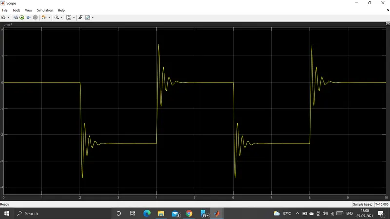
Since we position the plunger as output from ITMSB we have connected the port P to a PS-Simulink converter block where the physical values of the port P are converted to simulink value which is connected to the scope block for generating the graph of the change in the position of the plunger from port P of Ideal translational motion sensor block.
Now to provide a physical signal for operating the switch we have used the pulse generator block which generates a continuous square pulse.
BLOCKS USED :
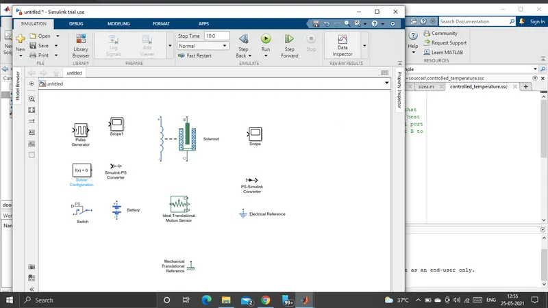
RESULT : I have simulated the model of doorbell using the solenoid block with the following details.
OUTPUT :

AIM : To simulate by use of thermistor to sense a temperature of a heater by following conditions.
INTRODUCTION :
THERMISTOR : A Thermistor is a resistor whose resistance is depend on temperature more so than in standard resistors.
The word is a combination of THERMAL AND RESISTOR.
Thermistors are widely used as inrush current limiters, temperature sensors Self re-setting over-current protectors and Self-regulating heating elements
COMPONENTS USED :
The basic components used to setup a simple cooling fan circuit are
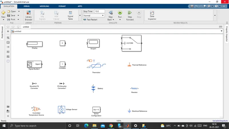
BATTERY, THERMISTOR, FAN, TRANSISTOR, RESISTOR
PROCEDURE :
Thermistor block is taken and placed in a model. And also battery block is taken positive port of the battery is connected to positive port of the thermistor block.
Resistor block is taken in to the model and its positive port is connected to negative port of thermistor block.The negative port of resister is connected to negative port of the battery block.
Now the electrical reference block is taken and it is connected to the negative terminal of the battery block which represents the earthing of the circuit.
Now to represent a voltmeter a Voltage sensor block is taken and is connected parallel to resistor block because to measure voltage across a component. Voltmeter should be always connected parallel to that component.
Thus we have completed the simple circuit model, But we need some physical quantites to as signal for thermistor to work.
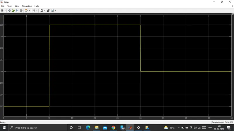
Now we have to give different temperatures to this controlled temperature source block we need to send temperature signals.To send these signals we usedx signal builder block which we can send any type of signals as inputs.
After the values given to signal builder block before connecting it to the controlled temperature source we need to convert these signals in to a physical value.So to convert we used Simulink-ps converter block. So now port B of the controlled temperature source is connected to port A of the thermister block.Port A of the controlled temperature source is connected to thermal reference block.
In controlled temperature source block a positive temperature difference causes the temperature at port B to be greater the temperature at port A.
Now the output of the voltage sensor block is connected to display block first and before connecting to the display block a PS-Simulink converter is used to convert physical values to simulink values.
Now when we run the simulation and double click on the display block we will get the voltage.
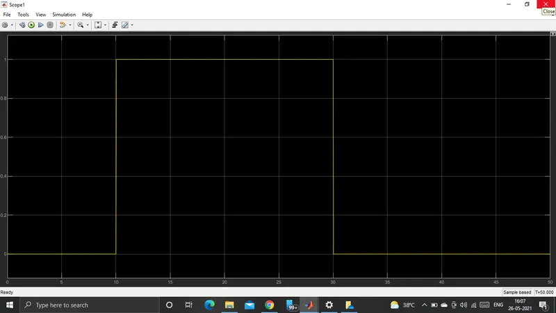
OUTPUT :
CONCLUSION :
Thus,Both the objectives were achieved succesfully.
Similar approach can be used for simulating other physical devices using simulink.