Rahul
AIM : To create pv diagram and calculation of thermal efficiency of otto cycle.
INTRODUCTION : Otto cycle is also called as CONSTANT VOLUME CYCLE. It is a spark ignition piston engine. It converts chemical energy in to thermal energy. The otto cycle describes how the internal combustion engine works
EXPRESSION FOR EFFICIENCY OF OTTO CYCLE :
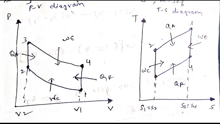
Process 1-2 = Reversible adiabatic (isentropic) compression
process 2-3 = constant volume heat addition
Process 3-4 = Reversible adiabatic (isentropic) expansion
process 4-1 = constant volume heat rejection
EQUATIONS :
HEAT ADDITION AT CONSTANT VOLUME IS GIVEN BY
qa = mcv(t3-t2) (m=1)
cv(t3-t2)
qr = mcv(t4-t1)
cv(t4-t1)
Work done = cv[(t3-t2)-(t4-t1)]
Efficiency of otto cycle is given by
notto = work done/heat a
notto = 1-(t4-t1)/(t3-t2)
for process (1-2) Reversible adiabatic(compression) process
t2 = t1(rc)^gamma-1
for process (3-4) Reversible adiabatic(expansion) process
t3 = t4(re)^gamma-1
notto = 1-1/(r)^gamma-1
PROCEDURE :
EXPLAINATION OF CODE
In the otto cycle the engine geometric parameters are
Bore, Stroke, Connecting rod, Compression ratio
Using the formula calculating the swept volume and clearance volume
v_swept = (pi/4)*bore^2*stroke
v_clearance = v_swept/(cr-1)
now v1 = v_swept+v_clearance
v2 = v_clearance
After obtaining the v1 p1 t1 and cr then the volume, pressure and temperature as other stages can be calculated using following equations
Pv^gamma = constant
Pv = mRT
FUNCTION CODE :
function [v] = engine_kinematics(bore,stroke,con_rod,cr,start_crank,end_crank)


%piston kinematics

a = stroke/2

r = con_rod/a


v_s = (pi/4)*bore^2*stroke;
v_c = v_s/(cr-1);

theta = linspace(start_crank,end_crank,100)
term1 = 0.5*(cr-1);
term2 = r+1-cosd(theta);
term3 = (r^2-sind(theta).^2).^0.5;

v = (1+ term1*(term2 - term3)).*v_c;

end
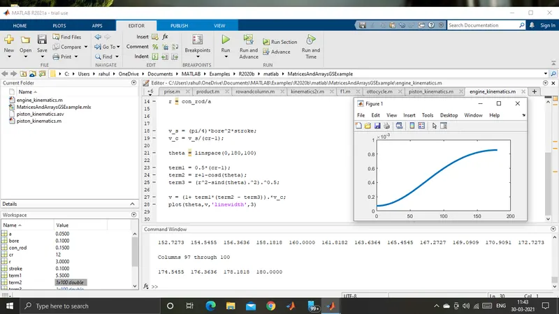
The above code is to calculate the volume inside the combustion chamber changes. So the total code is saved in the function code.
FUNCTION is a piece of code that can be renewed by calling its name in a right parameters
so we need to basically call to this particular program so we use FUNCTION code.
OUTPUT OF FUNCTION CODE IS
CONCLUSION
The above program describes that the volume inside the combustion chamber is not going linearly. The volume does not goes linearly inside the CC.
MAIN CODE :
%state variables
p1 = 101325;
t1 = 500;
t3 = 2300;
%engine geometric parameters
bore = 0.1;
stroke = 0.1;
con_rod = 0.15;
cr = 12;
gamma = 1.4;

v_swept = (pi/4)*bore^2*stroke;
v_clearance = v_swept/(cr-1);

v1 = v_swept+v_clearance;
v2 = v_clearance;

%state variables at point 2

%p2v2^gamma = p1v1^gamma
%p2 = p1*(v1/v2)^gamma = p1*cr^gamma
p2 = p1*cr^gamma
constant_c = p1*v1^gamma;
 v_compression = engine_kinematics(bore,stroke,con_rod,cr,180,0)
 p_compression = constant_c./v_compression.^gamma;


%p1v1/t1 = p2v2/t2 | t2 = p2v2t1/p1v1
t2 = t1*(p2/p1)*(v2/v1)
constant_c = p1*v1^gamma

%state variable at point 3
v3 = v2
%p3v3/t3 = p2v2/t2
p3 = p2*t3/t2
constant_c = p3*v3^gamma;
 v_expansion = engine_kinematics(bore,stroke,con_rod,cr,0,180)
 p_expansion = constant_c./v_expansion.^gamma;


%state variable at point 4
v4 = v1

 %p3v3^gamma = p4v4^gamma| p4 = p3(v3/v4)^gamma
p4 = p3/cr^gamma

%thermal efficiency

efficiency = 1-1/cr^(gamma-1)

hold on
plot(v1,p1,'*','color','r')
plot(v_compression,p_compression)
plot([v2 v3],[p2 p3],'color','r')
plot(v2,p2,'*','color','r')
plot(v3,p3,'*','color','r')
plot(v_expansion,p_expansion)
plot(v4,p4,'*','color','r')
plot([v4 v1],[p4 p1],'color','r')
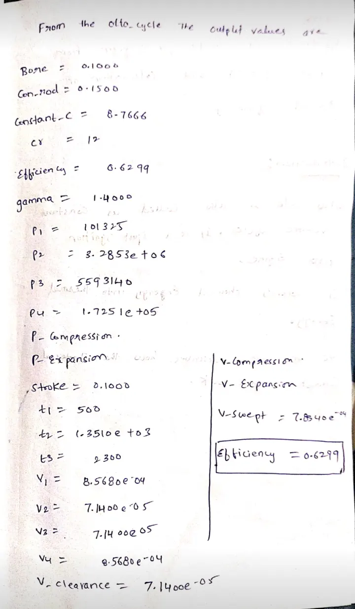
CODE OUTPUT :
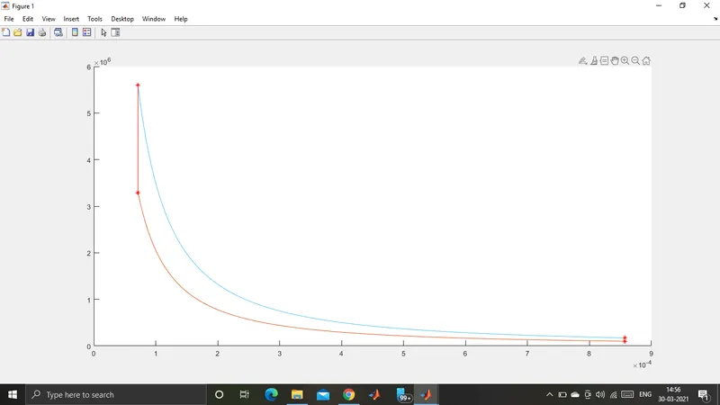
PLOT OUTPUT :
CONCLUSION :
(1) The thermal efficiency is calculated to be 0.6299 or 62.99%.
(2) The pv diagram clearly shows that changes in isentropic process are a curve and a straight line.