Week -2
Aim: Make a Simulink model of Doorbell using solenoid block
Objective:
- When the switch is closed the electromagnet receives electrical power from the battery and pulls the metal arm to hit the bell producing sound.
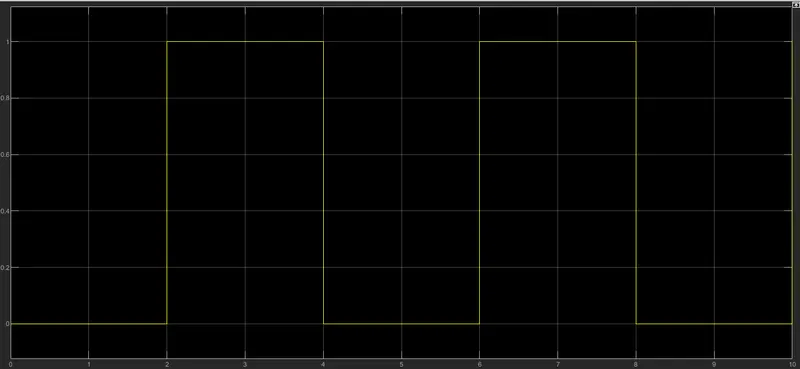
- Create a situation where the switch is closed for 2 seconds and then released.
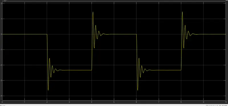
- Observe the physical movement of the plunger.
This is block diagram of given system.
Solenoid
- Solenoids are a type of electric motor. They are commonly used in cars as heavy duty relays. The technical definition of a solenoid is a device or motor that can produce back and forth, or linear, motion when a force is applied. Solenoids will respond to hydraulic, pneumatic or electrical force.
-
A Solinoid is created by winding copper wire over a cylindrical casing. when electricity is passed through the coil the solenoid acts like a magnet. In this project, we have used a solenoid valve to demonstrate the working of the doorbell
This is simulik model of doorbell using different simulink blocks and solenoid block.
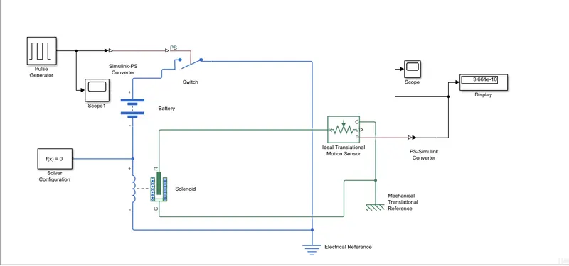
1. Pulse Generator: The Pulse Generator block generates square wave pulses at regular intervals The block waveform parameters amplitude, pulse width, period and phase delay determine the shape of the output waveform
2. Simulink-PS Converter: Converts the unitless Simulink input signal to a physical signal
3. Scope: Display signals generated during simulation.
4. Switch: Switch controlled by an external physical signal
5. Battery: The Battery block represents a simple battery model
6. Solenoid: Model electrical characteristics and generated force of solenoid
7. Ideal Translational Motion Sensor: The Ideal Translational Motion Sensor block represents a device that converts an across variable measured between two mechanical translational nodes into a control signal proportional to velocity or position. You can specify the initial position (offset) as a block parameter. The sensor is ideal since it does not account for inertia, friction, delays energy consumption, and so on
8. Mechanical Translational Reference: The Mechanical Translational Refererice block represents a reference point, or frame for all mechanical translational ports. All translational ports that are rigidly clamped to the frame (ground) must be connected to a Mechanical Translational Reference block
9. Electrical Reference: The Electrical Reference block represents an electrical ground. Electrical conserving parts of all the blocks that are directly connected to the ground must be connected to an Electrical Reference block. A model with electrical elements must contain at least one Electrical Reference block.
10. Solver Configuration: The Solver Configuration block specifies the solver parameters that your model needs before you can begin the simulation.
11. PS-Simulink Converter: Convert physical signal into Simulink output signal.
Input :
Output :
Aim : Use a thermistor to sense the temperature of a heater & turn on or turn off the fan.
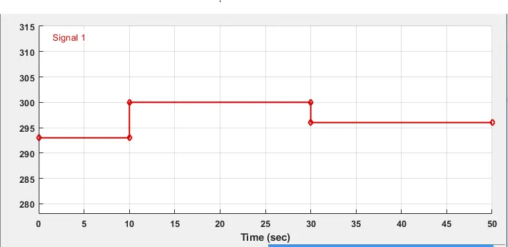
Condition : Temperature source: 20 °C from 0 to 10 seconds, 27 °C from 10 to 30 seconds, 23 °C from 30 to 50 seconds Fan conditions: ON if the temperature above 25 °C, OFF otherwise.
Thermistor :
- The thermistor is a kind of resistor whose resistivity depends on surrounding temperature. It is a temperature sensitive device.
- The word thermistor is derived from the word, thermally sensitive resistor.
- The thermistor is made of the semiconductor material that means their resistance lies between the conductor and the insulator.
This is simulink model of fan using thermistor.
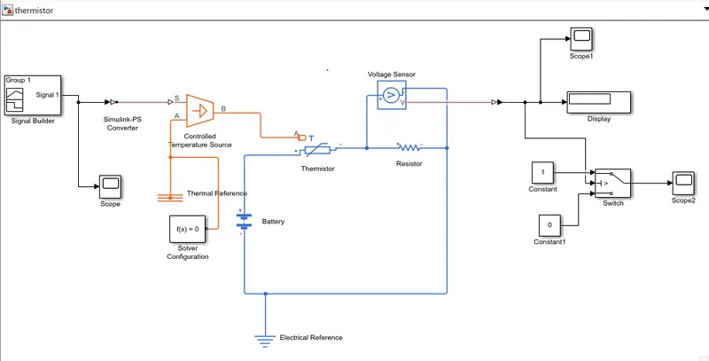
1. Signal Builder - Generating the signal by feeding the temperature value at different time interval
2. Simulink-PS Converter - Converts input simulink signal innto physical signal
3. Thermistor - Senses temperature for adjusting resistance
4. Controlled temperature source - This block represents an ideal energy source in a thermal network that can maintain a controlled temperature difference regardless of the heat flow rate. The temperature difference is set by the physical signal port S. A positive temperature difference causes the temperature at port B to be greater than the temperature at port A
4. Battery Power Source of thermistor
5. Electrical Reference - Indicating that the connections are grounded
6. PS-Simulink - To converts physical signal to simulink signal
7. Voltage Sensor Senses voltage accross the circuit.
8. Display Shows threshold value of voltage
9. Switch - To control output voltage at particular threshold value
10. Scope - For obtaininng the graph for general time, velocity, position domain of the signal
Input :
Output :
Fan's ON/OFF condition is satisfied
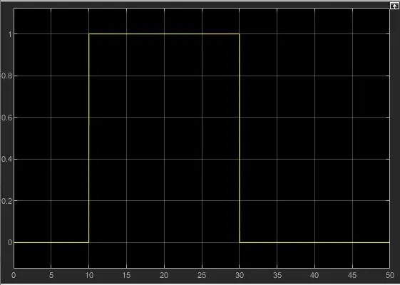
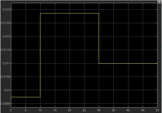
- We get fan is off between 0 to 10 second because here temperature is 20 degree which is less than 25 degree
- We get fan is on between 10 to 30 second because here temperature is 27 degree which is greater than 25 degree
- We get fan is off between 30 to 50 second because here temperature is 23 degree which is less than 25 degree
- hence we achived our given condition.