Week 14 challenge
BUTTERFLY ASSSMBLLY
Step wise representation of butterfly assembly is given below
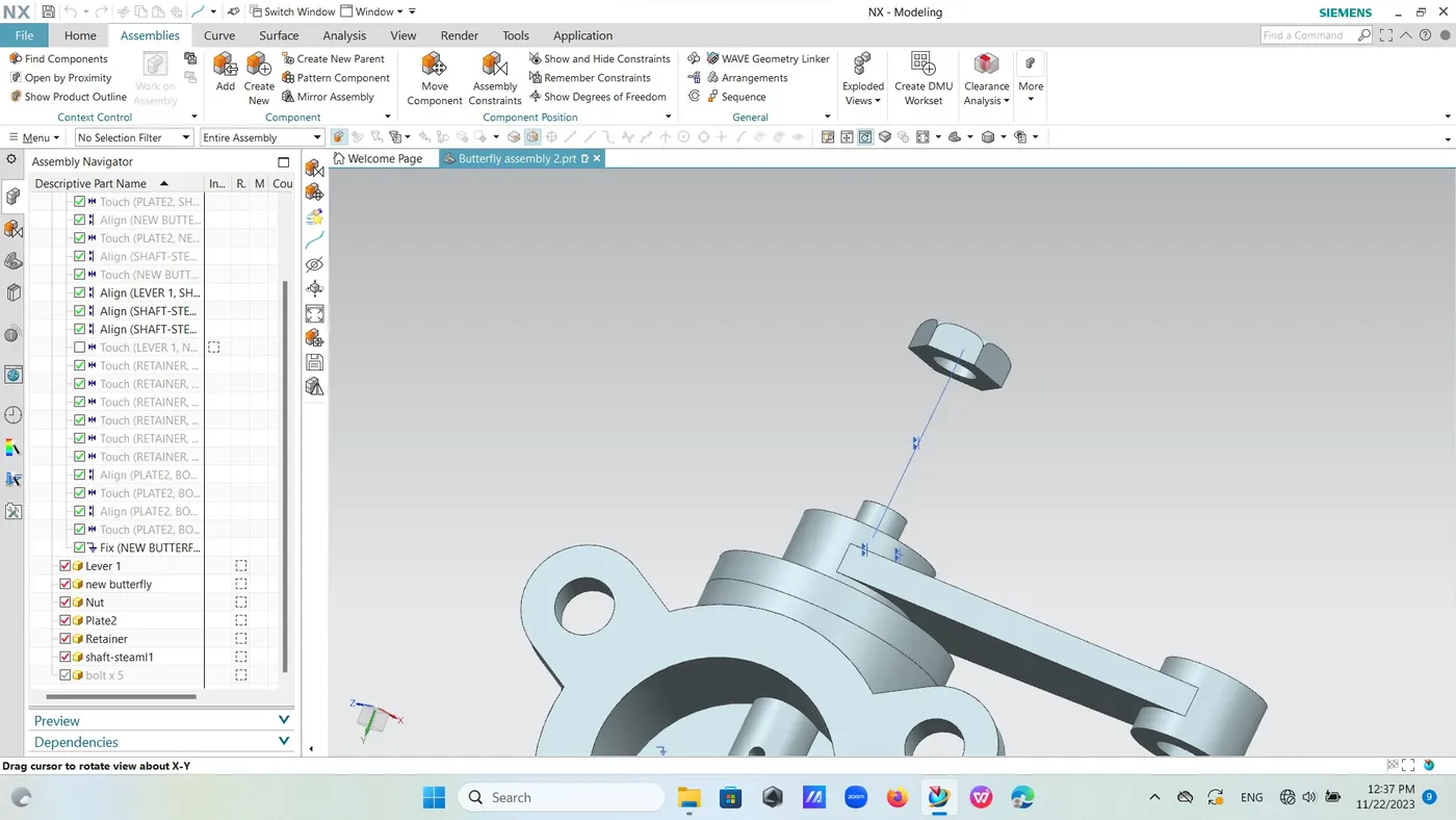
1. Open NX CAD go to new file select assembly instead model because we are doing assembly of butterfly drawing and name it Butterfly Assembly.
2. Now,go to assembly through ribbon bar and and click on Add then select all the part of this butterfly assembly this parts must be in one folder and save it on desktop or respected folder where all the files are saved otherwise assembly will not open.
3. Select component anchor assembly and assembly location absolute work part placement move and save it.
4. Now isolate each part like lever,nut,plate,retainer and bolt form main body.
5. Now go to assembly and then move component select that component and align or bring closer to its main body and related part together.
6. First bring shaft closer to main body by using move component command then bring plate closer to shaft then go to constrain component and select touch align or geometry to constrain orientation is touch.now select orientation infer center or axis then select axis of hole of plate and hole of shaft to align together and align them then select orientation touch and first select plate surface then shaft surface because plate will strike on plate suddenly if shaft surface is selected before plate suddenly .will form one unit and then if move it will move together.
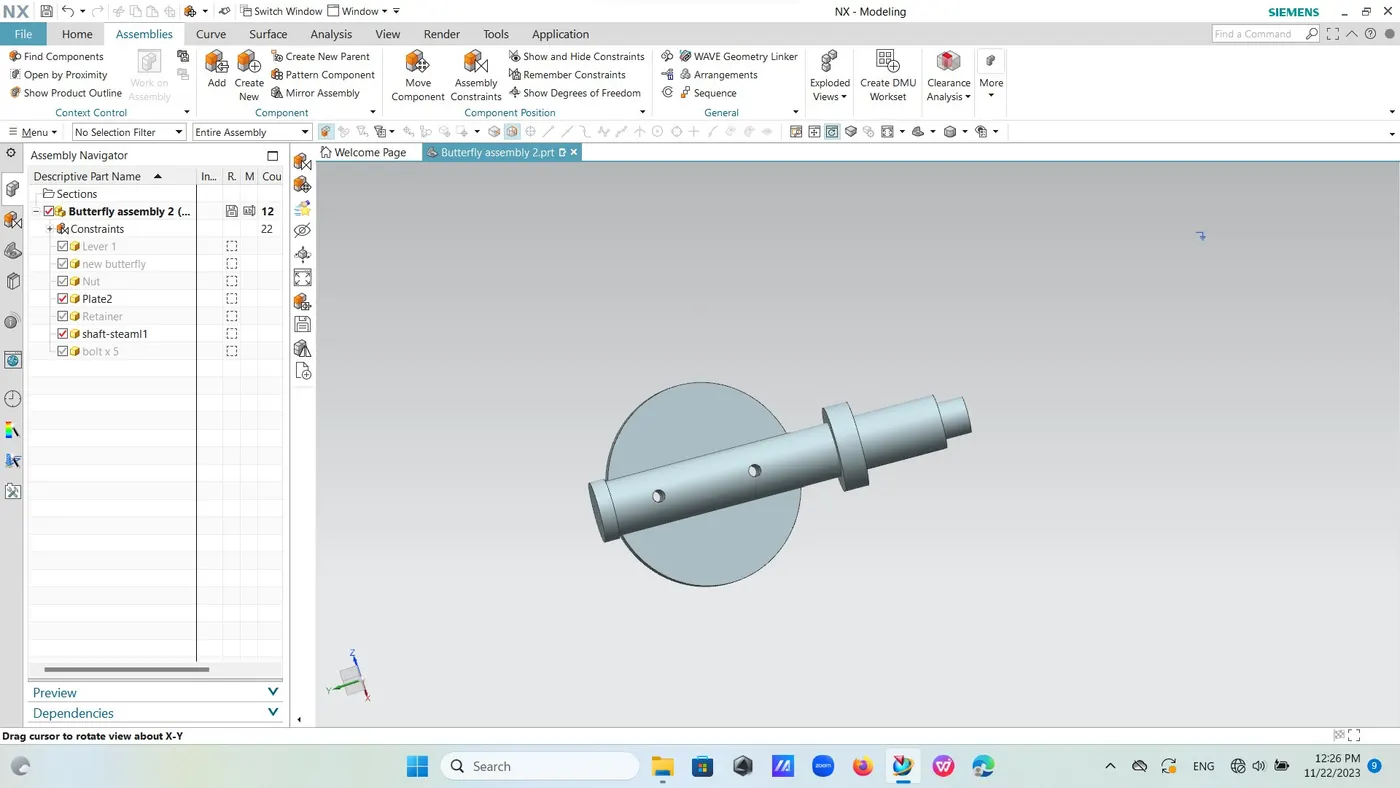
7. Now we have to align shaft axis with axis of the body so go to constrain command align select orientation and select infer axis and align shaft and body together now we have to align outer periphery of plate to inner body so go to orientation again and select touch constrain and select outer surface of plate and inner surface of body it will make surface to surface contact.
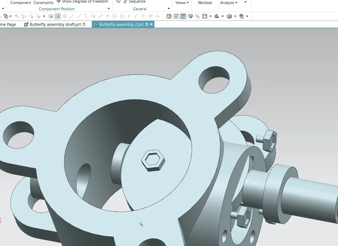
8. Now we have to fix retainer plate with main body so will bring retainer plate closer to main body first then will align axis of retainer with axis of main body so go to orientation then select axis of retainer plate and axis of body then again orientation and select touch command then select surface of retainer plate and surface of body to fix together.
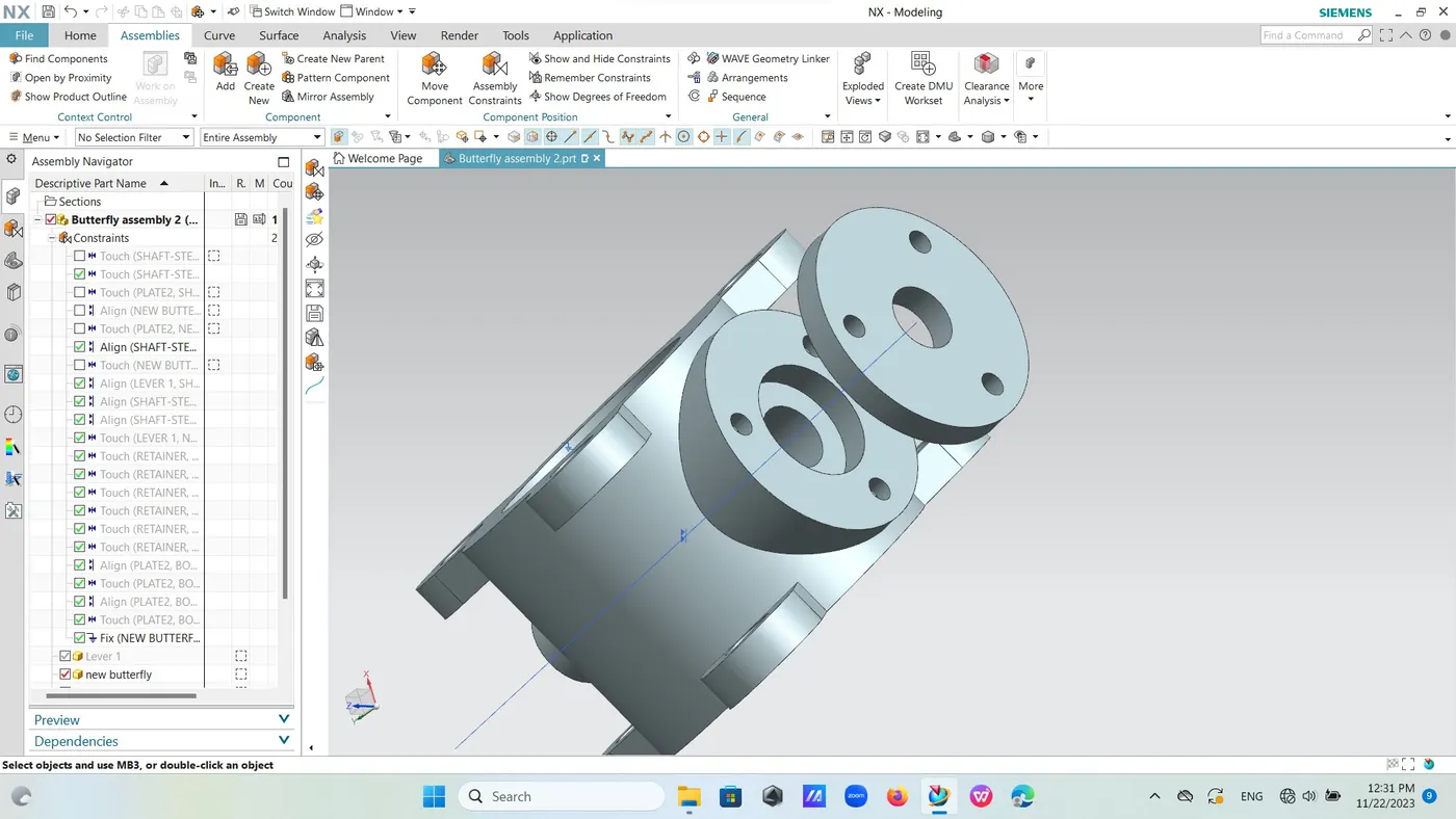
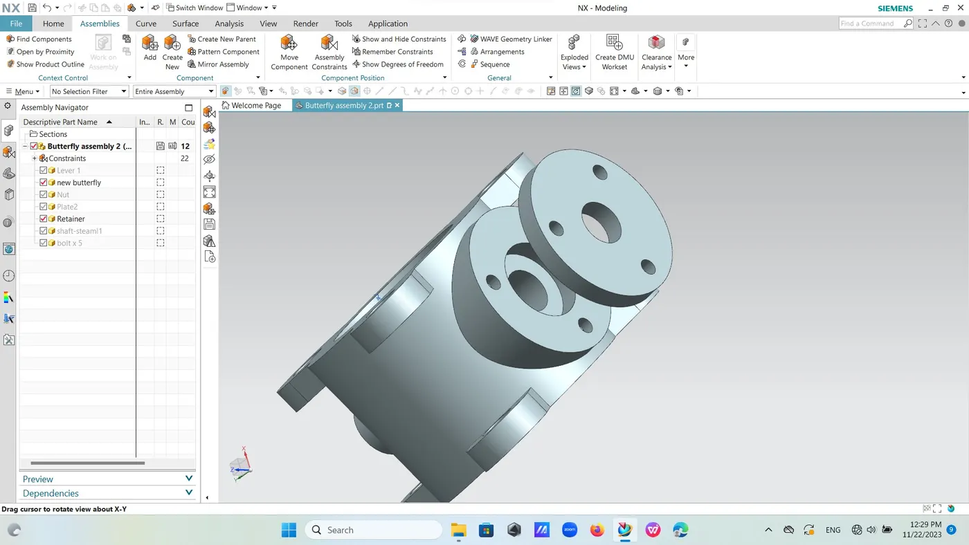
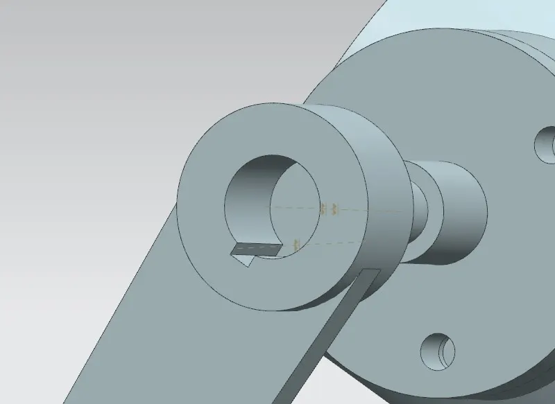
9. Now we have to fix liver with main body so bring lever closer to main body and then go to constrain command through ribbon bar and here instead of doing surface to surface contact of lever and main body we will use align option through orientation because we have to align rectangular slot of key way with slot of shaft.
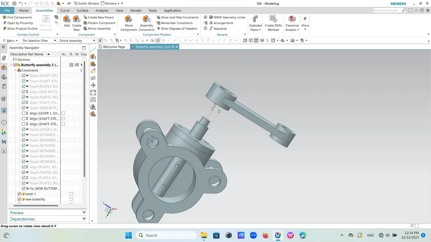
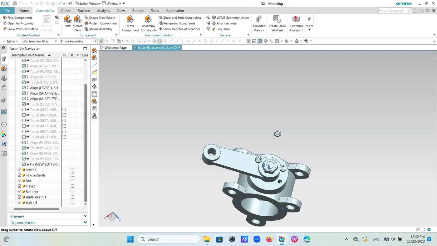
10. Now final step is to fix nut over it so bring nut closer to body and select orientation and axis or infer option so align axis of nut with axis of shaft and then surface of nut with surface of retainer plate.
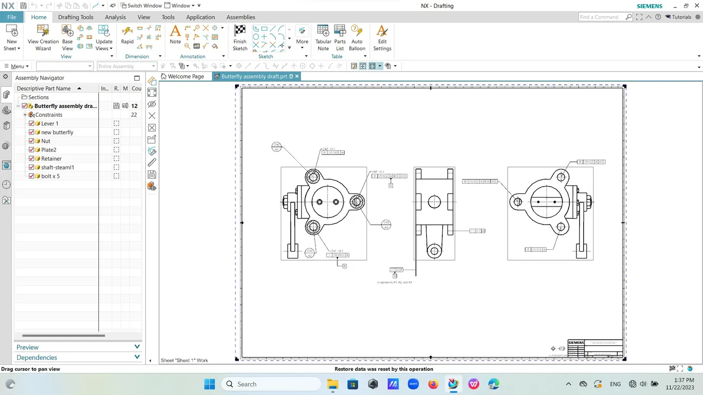
Drafting. :-
l Go to Application through ribbon bar Go to Application select drafting sheet selection as A0 size and then leave population of title box ,view creation wizard cancel it and ratio as 1:2.
l Go to border line of sheet and click Right click button of mouse .
l Will options select Add base view tile box will pops up shows model view and select orient view tool, and select view that you wand selecting Top view.
11. Now select view that you want and then normal and x axis if have not taken orientation properly then click on face and select front view.
12. Now take its projected view and then third view is projected view of second view exact reverse or mirror image of first one.
13. Then go to search command and type arc select arc point point point and then select three points on circle exit and then double click on that arc and then select full circle notice here we have taken ratio 1:2 so actual circle diameter is different form shown or this is double that of previous .
14. Take dia meter 20 that is 40 as per 1:2 ratio and so radius is 20 as per point point point arc select three points on that outer eye circle and and also take circle of diameter 20 there for inner circle .
15. Now we have give hatching lines so type hatch in search box and click on hatching lines select boundary as outer circle and inner circle so hatching will be constrain in between two boundaries.
16. Now we have do same process for two circles again so will press CRT +T and select outer boundary and inner boundary of circles and transfer it point to point from center.
17. Now go to datum target and select three holes one by one and call them A1,A2 and A3. select setting and test size as 6mm and balloon size is 30mm.
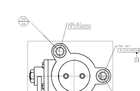
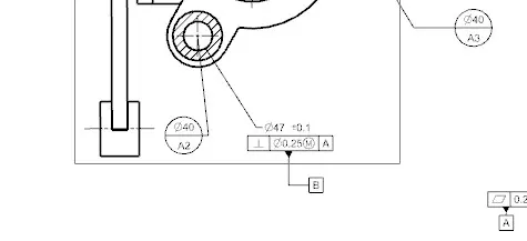
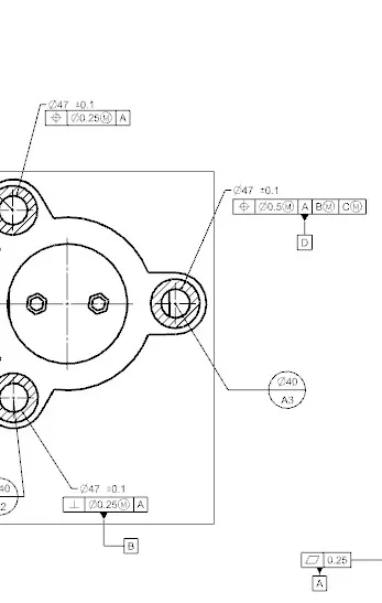
18. Now hide arc circle which is inner and give it dimension of 23.5 mm with tolerance of 0.1through rapid dimension .
19. Now go to feature control frame and give it position tolerance of 0.25 mm with respective datum A .
20. Now go to nest hole give it perpendicularity of 0.5mm with maximum material condition with respective datum A and call it datum B.
21. Third hole of position tolerance of 0.5 mm with maximum material condition with respective A,B and C with maximum material condition.
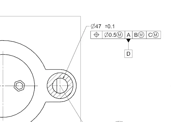
22. Called third feature frame as datum D in last because we have to coincide axis of other side wing hole with this hole .
23. Now to second projected view here take one line straight to downward form point and then call it as datum A which include datum A1,A2, and A3.with flatness of 0.25 mm.
24. Now third projected view which mirror image of first one will give rapid dimension to all three hole and then add feature control frame which include position tolerance of 0.5 with maximum material condition at datum B and A .same as position tolerance of 0.5 with maximum material condition with respective datum A.
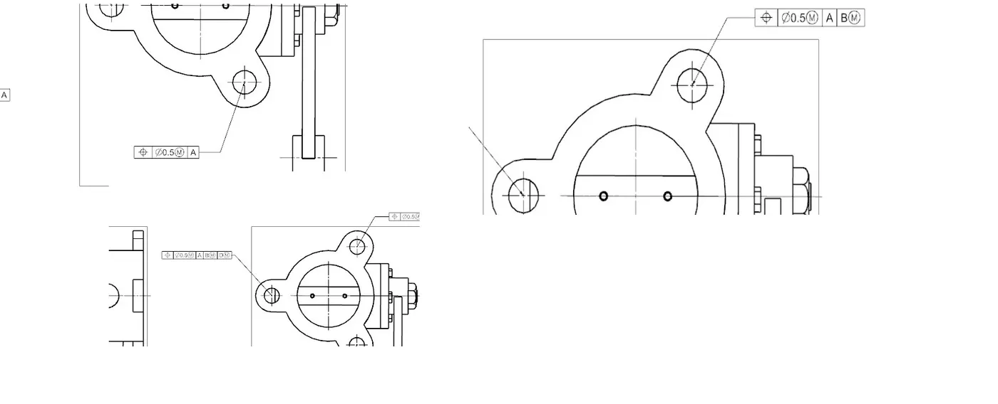
25. Third hole which is exact mirror of datum C having potion tolerance of 0.5 with maximum material condition of with respective datum A,B and D .