Week 14 challenge
AIM:- The aim of this project is to model a butterfly valve and to apply GD&T to the different parts of the butterfly valve and the assembly.
Parts of Butterfly Valve :-
- Body of Butterfly Valve
- Shaft
- Retainer
- Disc
- Lever
- Nut
- Screw
- Final Assembly
1.BODY OF BUTTERFLY VALVE:-
- 1.Initially, the sketch for the body of the butterfly valve is drawn using the circle tool in NX software.
- 2.After extruding the sketch which is drawn,the ears of the Butterfly valve is drawn and then it is copied on both sides of the cyclindrical portion.
- 3.Now, the datum plane option is used to create cyclidrical portion and the counter bore option is used to provide a counter bore to the part with the specified dimensions.
- 4.Finally, the hole is provided for the mounting of the body and it is saved in the required folder.
2. Shaft:-
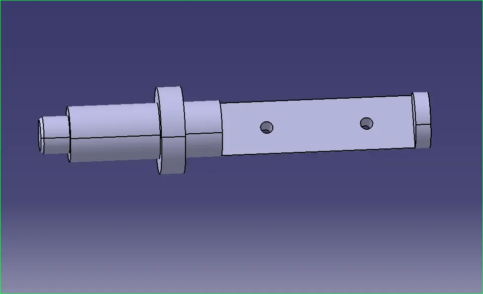
- The two-dimensional design shown in the figure is used to convert the design into a three-dimensional model in various operations.
2. The Rotate option is used to create a shaft with a 360 degree rotation.
3. Now use the Extrude (Subtract) option to create a recess in the front and back of the shaft.
4. Finally, drill two 12.5 mm diameter holes in the slot behind the shaft and store the parts in the required folder.
DRAWING OF SHAFT:-
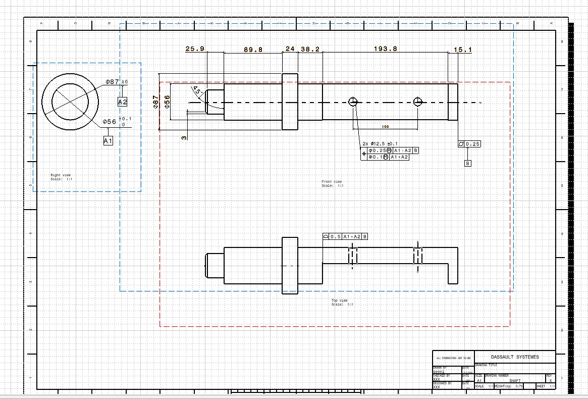
- 1.Here,Only two datums A and B are given since the movement of shaft in one direction is required as per it's function.
- 2.Datum A1 and A2 are given which comes in contact with the body of the butterfly valve.
- 3.Datum B is provided at the base of the shaft.
- 4.All the other tolerances like profile of a surface,flatness, composition position tolerance and the size tolerances are given to the other features.
A "retainer" in the context of mechanical engineering and design typically refers to a component that holds or retains another part or parts in place within a machine or assembly. It is a critical element in various mechanical systems, ensuring that components do not move or become dislodged during operation. Retainers are commonly used in conjunction with bearings, seals, fasteners, and other components to maintain their proper position and alignment.
Here are some key aspects to consider when discussing retainers and CAD drawings:
**1. Purpose of a Retainer:**
- Retainers are designed to prevent the axial or radial movement of components within a mechanical system.
- They ensure that bearings, seals, or other rotating parts remain in their designated positions, maintaining proper alignment and functionality.
**2. Types of Retainers:**
- Retainers come in various forms, depending on their intended application. Common types include:
- Bearing Retainers: Used to secure rolling bearings (ball bearings, roller bearings) in place.
- Seal Retainers: Hold seals in position to prevent leaks.
- Snap Rings: Circular or C-shaped components used to secure cylindrical parts onto shafts or within housings.
- Fastener Retainers: Used to secure fasteners like screws, bolts, or nuts, preventing them from loosening due to vibration.
**3. Materials and Manufacturing:**
- Retainers are typically made from materials such as plastic, metal, or composite materials, chosen for their durability and compatibility with the components they retain.
- The manufacturing process may involve machining, injection molding, stamping, or other methods, depending on the material and design.
**4. CAD (Computer-Aided Design) Drawings:**
- CAD drawings are technical illustrations created using computer software to represent the geometry, dimensions, and specifications of engineering components and assemblies.
- When designing a retainer, CAD drawings are essential for:
- Creating a detailed 2D or 3D representation of the retainer's geometry.
- Specifying exact dimensions, tolerances, and material properties.
- Modeling how the retainer fits within the larger assembly and interfaces with other components.
- Communicating design intent and specifications to manufacturing teams.
**5. Considerations in CAD Design:**
- When creating CAD drawings for a retainer, engineers and designers need to consider factors such as:
- Fit and clearance with the components it retains.
- Compatibility with lubricants and environmental conditions.
- Tolerance stack-up and manufacturing tolerances.
- Ease of installation and maintenance.
- Material selection based on factors like load-bearing capacity and corrosion resistance.
In summary, a retainer is a crucial component in mechanical systems, and CAD drawings play a vital role in designing, specifying, and manufacturing these components accurately. Detailed CAD drawings ensure that the retainer functions as intended, maintaining the integrity and performance of the larger mechanical system.
Holding drawing:-
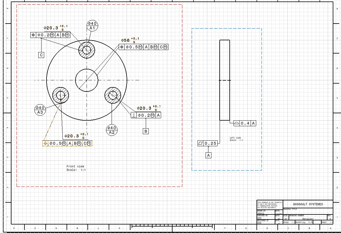
- After modeling, the part is transferred to the drawing part where three bases A, B, C are applied.
2. Provide target areas A1, A2, and A3 (initial section A) on one side that contacts the top of the support body.
3. Datum-B is applied to one of the holes where the retaining screw is inserted.
4. Datum-C is applied to the other hole of the holder.
5. Finally, other tolerances such as the square of the surface, position and profile are applied to the holes and other holding surfaces and the map is saved in the required folder.
Certainly, in CAD design, the disc plate in a butterfly valve assembly is typically represented as a key component within the overall valve assembly. Here's how it is typically designed and represented in CAD:
**1. CAD Model of the Disc Plate:**
- The disc plate is created as a 3D model within the CAD software. It is designed to match the actual physical shape and dimensions of the real-world component.
**2. Disc Geometry:**
- The disc plate is modeled with its circular or semi-circular shape, and its dimensions are specified accurately based on the valve's design specifications.
**3. Attachment to Shaft:**
- The disc plate is connected to a central shaft, which allows it to rotate within the valve body. This connection point is accurately designed and represented in the CAD model.
**4. Material Selection:**
- The CAD model includes information about the material from which the disc plate is constructed. This is important for understanding its mechanical properties and interactions within the assembly.
**5. Rotation Mechanism:**
- In the CAD model, the disc plate is typically designed to show its range of motion. It can be rotated from fully open (parallel to the flow) to fully closed (perpendicular to the flow), and this rotation mechanism is accurately depicted.
**6. Sealing Surface:**
- The CAD model may include details of the sealing surface of the disc plate. When the valve is in the closed position, this surface contacts the valve seat to create a seal. The sealing surface is designed with precision to ensure a proper seal.
**7. Actuation Interface:**
- If applicable, the CAD model may incorporate features related to the actuation mechanism. This could include mounting points for actuators, levers, or gears used to control the disc plate's position.
**8. Integration with Valve Body:**
- In the complete CAD assembly of the butterfly valve, the disc plate is integrated into the valve body. This assembly includes the valve body, shaft, disc plate, and other relevant components.
**9. Tolerances and Clearance:**
- CAD design includes specifications for tolerances and clearances to ensure that the disc plate fits and operates correctly within the valve body without interference.
**10. Documentation:**
- Detailed engineering drawings and specifications are created in CAD to document the design of the disc plate. These drawings provide essential information for manufacturing and assembly.
CAD design of the disc plate in a butterfly valve assembly is a crucial step in the engineering process, allowing for precise visualization, analysis, and documentation of this critical component's design and function within the larger valve system.
PLATE:
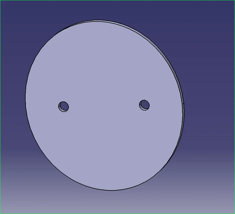
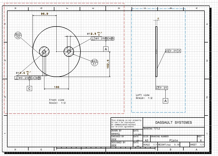
DRAWING OF DISC PLATE:-
- 1.The datums are applied to the disc in the drafting section.
- 2.Datum target Areas A1,A2(Primary Datum-A) is given to one side of the disc which comes in contact with the Stem/Shaft.
- 3.A datum B is given to one hole of the disc and the other datum is given to the other hole.
- 4.All the other tolerances like Perpendicularity tolerance to datum B and position tolerance to datum C and profile of a surface tolerance is given to the outer boundary surface.
LEVER:
Creating a lever for a butterfly valve in CATIA V5 involves designing a component that allows manual operation of the valve, typically for opening and closing it. Here's a simplified overview of how you might create a lever in CATIA V5:
**1. Launch CATIA V5:**
- Open CATIA V5 and start a new part or assembly design, depending on your specific project requirements.
**2. Create a New Part:**
- If you're designing the lever as a standalone part, create a new part document.
**3. Sketch the Lever Profile:**
- Use the sketching tools in CATIA V5 to create the 2D profile of the lever. This profile should represent the lever's cross-section.
- Pay attention to the shape, dimensions, and any specific design features required for your lever.
**4. Extrude the Profile:**
- Extrude the 2D sketch to create a 3D representation of the lever.
- Specify the extrusion distance, which determines the length of the lever.
**5. Add Details:**
- Depending on your design, you may need to add details to the lever, such as holes for mounting or grip features for ease of use.
- Use CATIA's sketching and modeling tools to create these features.
**6. Fillets and Chamfers:**
- Round sharp edges or add chamfers as needed to ensure the lever is safe to use and ergonomically designed.
**7. Assembly Integration:**
- If the lever is part of a butterfly valve assembly, you'll need to ensure it interfaces correctly with other components in your assembly.
- Use CATIA's assembly design tools to assemble the lever with the valve body and other relevant parts.
**8. Material Assignment:**
- Assign a suitable material to the lever to ensure accurate weight and mechanical properties in your simulations or analyses.
**9. Document and Annotate:**
- Create engineering drawings with dimensions and tolerances for the lever.
- Add any necessary annotations to specify materials, finishes, or other details.
**10. Save and Export:**
- Save your lever design in CATIA V5's native file format. You can also export it to other file formats if needed for further analysis, manufacturing, or documentation purposes.
**11. Analysis and Testing (Optional):**
- If required, you can perform stress analysis, motion simulation, or other tests to ensure the lever's functionality and durability.
Please note that this is a simplified overview, and the actual design process may vary based on your specific project requirements and the complexity of the lever design. Additionally, if this lever is part of a butterfly valve assembly, you'll need to ensure proper integration and interaction with other valve components in your CATIA V5 assembly.
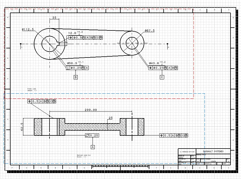
DRAWING OF LEVER:-
- 1.After the design of the lever, the drafting of the lever is done for applying the GD&T.
- 2.Three datums A,B,C are applied to the part.
A datum- To the bottom surface of the lever that comes in contact with the other surface.
B datum- It is applied to the hole where bolt comes in contact.
C datum- It is applied to the other hole to completely constraint the part.
Finally,all the other tolerances like position,Flatness,Profile of a surface are applied to the part.
6. Nuts:-
- Create a 3D model of the bead with the given dimensions.
2. First, extrude a hexagonal nut with a hole 25 mm deep and 37 mm in diameter.
3. Finally, use the rotate option to create a fillet with a radius of 10 mm.
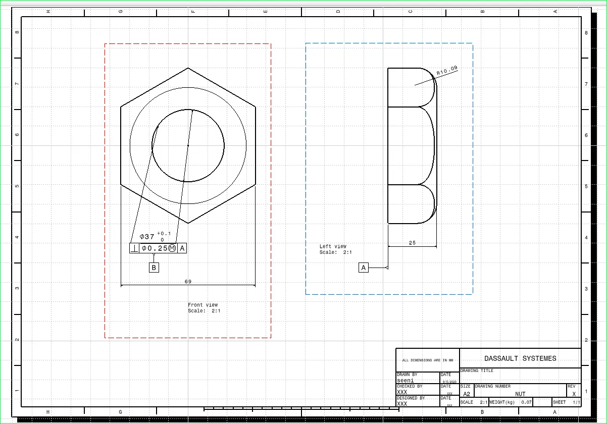
DRAWING OF NUT:-
- 1.After finished creating the design of nut,the drafting portion is opened for applying GD&T to the nut.
- 2.Now,the datums A and B are applied to the base of the nut and the hole of the nut.Perpendicularity Tolerance of .25 is given to the hole of the nut.
7.SCREW:-
This Screw helps to retain or to fix the Disc with the Shaft of the butterfly valve. It prevents the shaft from coming out of the body and keeps it in position for the proper functioning of the disc inside the body.
Butterfly Valve Assembly:
Creating a butterfly valve assembly in CATIA V5 involves assembling various components to form a functional valve system. Here's a high-level overview of how you can create a basic butterfly valve assembly in CATIA V5:
**1. Launch CATIA V5:**
- Open CATIA V5 and start a new assembly document.
**2. Import Valve Components:**
- Import or create the individual components of the butterfly valve assembly. These components typically include:
- Valve body
- Disc plate
- Valve stem
- Seals or gaskets
- Actuator (if the valve is automated)
- Bolts, nuts, and washers
**3. Position and Align Components:**
- Use CATIA's assembly tools to position and align the components correctly. Ensure that they are in their intended locations within the assembly.
**4. Mate and Constraint Components:**
- Apply mates and constraints to secure the components in place. Common constraints include:
- Coincident constraints to align faces or edges.
- Concentric constraints for shafts and rotating parts.
- Distance constraints to specify gaps or clearances.
- Angle constraints to control the rotation of the disc plate.
**5. Verify Movement:**
- If the valve is manually operated, check that the disc plate can rotate within the valve body.
**6. Add Fasteners:**
- Insert bolts, nuts, and washers to secure the valve components together. Use the appropriate fastening features and constraints to ensure proper assembly.
**7. Actuator Integration (Optional):**
- If the valve is automated, integrate the actuator into the assembly. Ensure that it is correctly aligned with the valve stem and can control the movement of the disc plate.
**8. Create Exploded Views (Optional):**
- For documentation or presentation purposes, you can create exploded views of the assembly to show how the components fit together.
**9. Material Assignment:**
- Assign materials to the components to ensure accurate weight and mechanical properties in simulations or analyses.
**10. Analysis and Testing (Optional):**
- If required, you can perform simulations, such as flow analysis or stress analysis, to validate the performance and structural integrity of the valve assembly.
**11. Document the Assembly:**
- Create engineering drawings with dimensions and tolerances for the valve assembly. Add any necessary annotations to specify materials, finishes, or other details.
**12. Save and Export:**
- Save the assembly in CATIA V5's native file format. You can also export it to other file formats for sharing or further analysis.
Please note that the complexity of a butterfly valve assembly can vary based on factors such as the valve's size, design, and intended application. Advanced assemblies may include additional components, such as gearboxes or controllers for automated valves. Additionally, detailed engineering and analysis may be required for specialized valve designs.
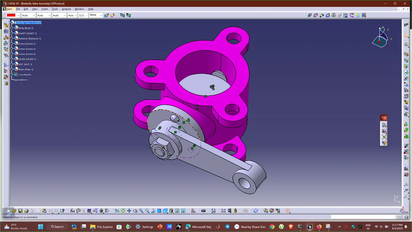
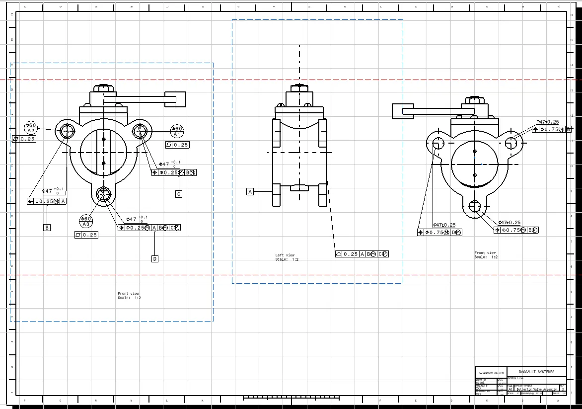
DRAWING OF ASSEMBLY:-
- 1.After the assembly of butterfly valve,the datums A,B,C,D are given.
- 2.Datum target areas A1,A2,A3 are given to the ears of the body with Perpendicularity tolerance and position tolerance.
- 3.Other tolerances like profile of a surface,flatness are given.Position tolerances with respect to the axis of B,C,D datums are given corresponding to the ears of the body.
- 4.Finally,the GD&T of assembly is saved in the required folder.
Conclusion:
Therefore,the Butterfly valve is created and the Geometric Dimensioning and tolerances are applied with the help of using CATIA V5 software.