Project 1
Block Diagram:
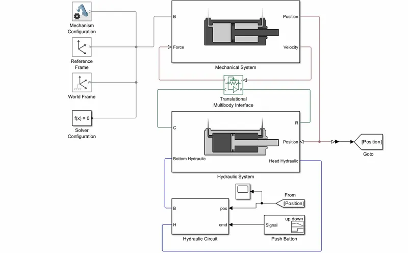
Definition of the project:
Hydraulic System:
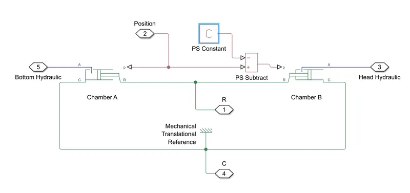
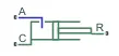 ==> The converter contains a variable volume of liquid. If Model dynamic compressibility is set to
 On, then the pressure evolves based on the dynamic compressibility of the liquid volume. The Mechanical orientation parameter lets you specify whether an increase in pressure moves port R away from or towards port C.
- Port A is the isothermal liquid conserving port associated with the converter inlet. Ports R and C are the mechanical translational conserving ports associated with the moving interface and converter casing, respectively.
- Here, we are used two Translational Mechanical Converter with PS constant and connected with Mechanical Reference.
Mechanical System:
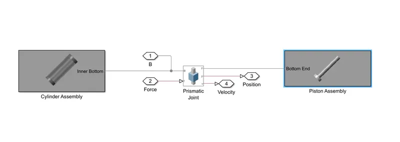
- Here, In mechanical system Cylinderical rods and Barrel solids are used to make Cylinder Assembly with full cylinder with hollow system. In the piston Assembly There will be Cylinderical rod with barrel rod was used to make piston.
- both cylinder Assembly and Piston Assembly are connected with Prismatic joints to make complete Piston cylinder Assembly.
- Here Mechanical Assembly and Piston Assembly connected by Translational Mutibody Interface for connecting Simscape mutibody interface with Simscape hydraulilc and mechanical sytem.
- For making Simscape multibody interface there will be World frame,reference frame, solver configuration and Mechanical configuration is provied for uniform gravity for the multibody system.
 ==> world frame (This block represents the global reference frame in a model. This frame is inertial and at absolute rest. Rigidly connecting a frame to the World frame makes that frame inertial)
 ==> reference frame (This block represents a reference frame with respect to which you can define other frames)
 ==> Mechanism configuration (The Mechanism Configuration block specifies the gravity and simulation parameters of the mechanism to which the block connects. The simulation parameters include the perturbation value for computing numerical partial derivatives during linearization and the iteration number for the joint mode transition)
 ==> prismatic Joint (
The Prismatic Joint block models a connection that limits the relative motion between two frames to one translational degree of freedom. This type of motion is common in hydraulic or pneumatic cylinders)
Hydraulic Circuit:
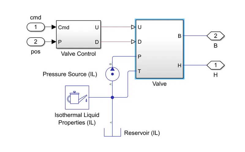
 ==> Isothermal Liquid (The Isothermal Liquid Properties (IL) block defines the liquid properties that act as global parameters for all the blocks connected to a circuit. The default liquid is water.)
 ==> Pressure Source (The Pressure Source (G) block represents an ideal mechanical energy source in a gas network. The source can maintain a constant pressure differential across its ports regardless of the mass flow rate through the source. There is no flow resistance and no heat exchange with the environment. A positive pressure differential causes the pressure at port B to be greater than the pressure at port A.)
Valve Switches:
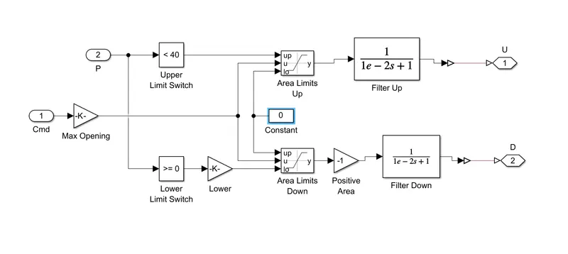
Valve:
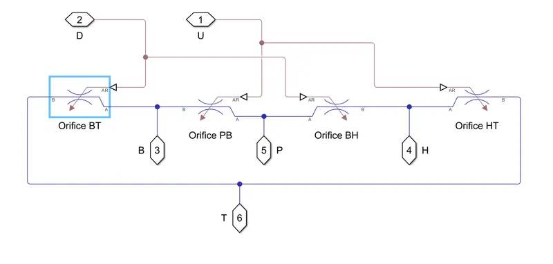
Here,4 variable orifices that are connected according to the port connection to flow the isothermal liquid in to the piston with controlled presure control and operated by the Switch mechaniam provide