Project - Position control of mass spring damper system
Solution:
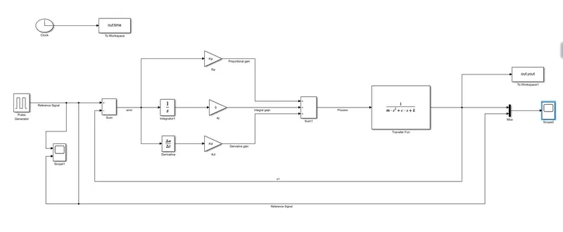
Obtain the transfer function of a mass spring damper system and use it in the model. Add a PID controller to adjust the force on mass so that its position follows a reference signal;
Program:
clc
clear all
%% position of spring mass damper sytem %%

m=3.6;  % mass of the spring mass system
k=400; % stiffness constant in N-m
c=100;  % Damping coefficient Nm/s

%%  natural frquency %%
fn=1.0;
wn=sqrt(k/m);
zeta=0.99;

%% state space model of the spring mass system %%
% mx_dot_dot+cx_dot+kx=0
% Apply laplace transform 's'
% m*s^2X(s)+c*sX(s)+k*X(s) =F(s) - laplace function
% X(s)/F(s) = 1/(m*s^2+c*s+k) =H(s) - transform function

s=tf('s');
G = wn^2/(s^2 + 2*zeta*wn*s + wn^2)
P = pole(G)

%% create state space model for the spring mass system %%
% x=x1, x_dot=x1,x_dot_dot=x2
% x_dot_dot=-k/m-c/m
% [x_dot;x_dot_dot] = [0 1;-k/m -c/m].*[x1;x2]+[0;1/m]u
% Y(t)=[1 0][x1;x2]+0u;

A=[0 1;-k/m -c/m];           % A matrix
B=[0;1/m];                   % B matrix

% p1=-zeta*wn+wn*sqrt(zeta^2-1);
% p2=-zeta*wn-wn*sqrt(zeta^2-1);
% P=[p1,p2];

K=place(A,B,P);
Kp=K(1)                     % proportional gain
Kd=K(2)                    % Derivative gain
Ki=0;                       % Integral gain

%end
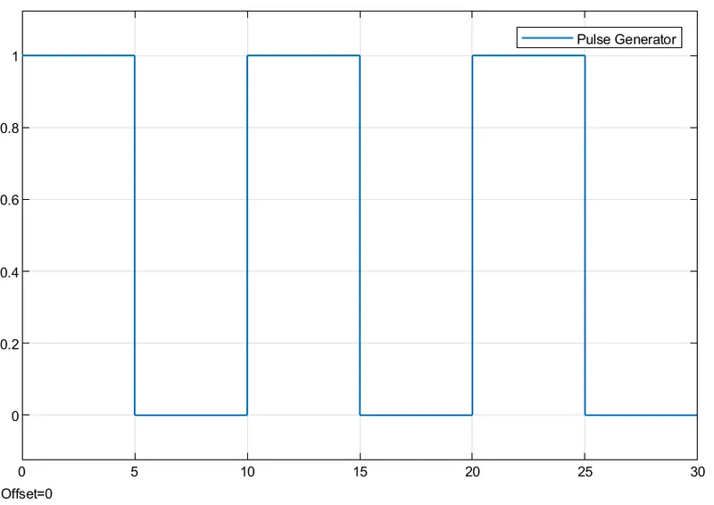
Refernce signal:
block Diagram:
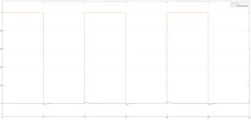
Adjusting Kp,Kd,Ki values to reduce the overshoot and settling time (Tuning the Ki value) and Checking many damping ratios (zetas)
Condition 1: Over damped system (zeta=1.5,Ki=0)-(Over damped system)
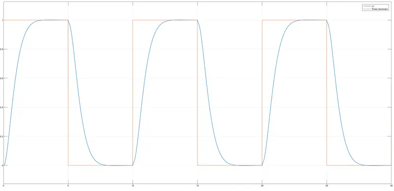
Condition 2:Ki=450,zeta=1.5 (Over damped sytem)-perfectly matched with reference signal
Condition 3:Ki=0,zeta=0.99 (Critically damped system)
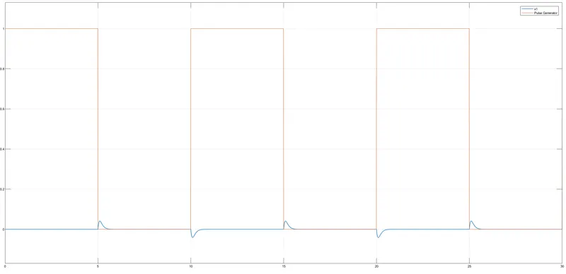
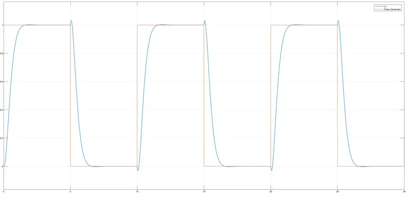
Condition 4:Ki=750,zeta=0.99 (Critically damped system)
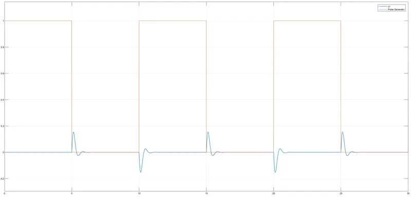
Condition 5: Ki=0,zeta=0.5;(under damped system)
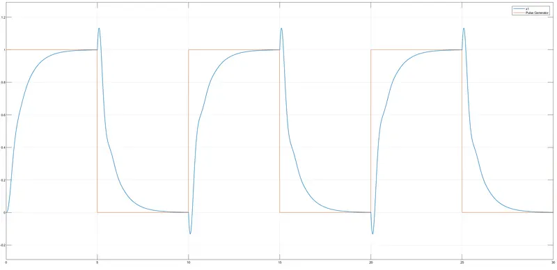
Condition 6:Ki=500,zeta=0.5;(Under damped system)
Summary:
From the above conditions zeta=1.5 ki=0,Initial condition=0.01 There is less raising time and more steady state error.
Ki=450 we get less raising time