Week 14 challenge
ASSEMBLY OF BUTTERFLY VALVE USING NX CAD
To assemble all parts of butterfly valve. open assembly window, add components and assemble them using assembly constrains.
(i) Butterfly valve body or base
Butterfly valve body is added into the assembly working environment and is fixed in its position using fix assembly constrain.
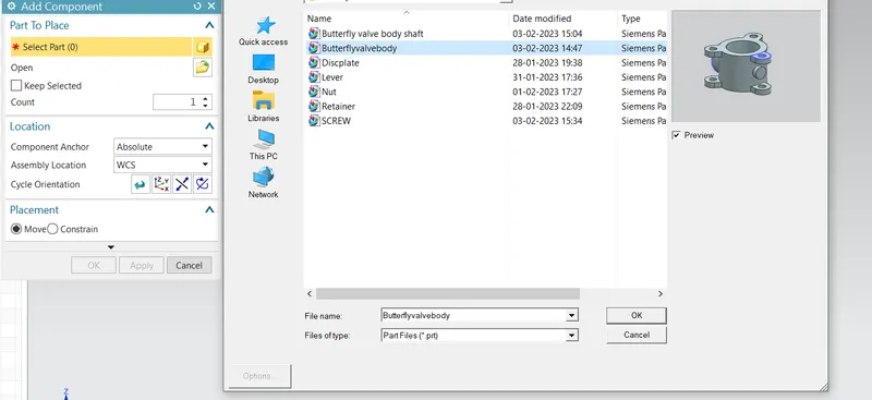
Fig. represents the Butterfly valve body being selected from the folder
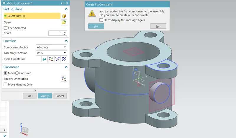
Fig. represents the Butterfly valve body being added to the assembly environment
(ii) Shaft
The shaft is called out in the assembly environment and constrains are applied to 5 DOF. The datum features on shaft are on cylindrical surfaces and planar surface. The cylindrical surface datum feature forms a datum axis - it constrains two rotations - about y and z axes and two translations - along z and y directions.
The other datum feature is a planar surface that from a datum plane. This datum plane constrains one translation - along x direction.
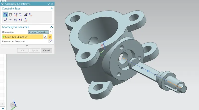
Fig. represents the shaft DOF constrained by coinciding the centre axes of shaft and butterfly valve body
(ii) Disc plate
The disc plate is constrained in all of its DOF. It has three datum features, one planar feature (datum plane), two cylindrical surfaces or hole features (datum axis). The datum plane constrains the disc plate in 3 DOF - one translation - along z direction, two rotations - about x and y axes.
The second datum is an axis that constrains two translations - along x and y directions. The third datum is an axis that constrains one rotation - about z axis.
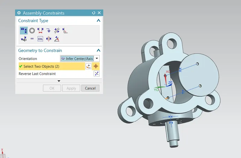
Fig. represents the disc plate DOF constrained by datum axes
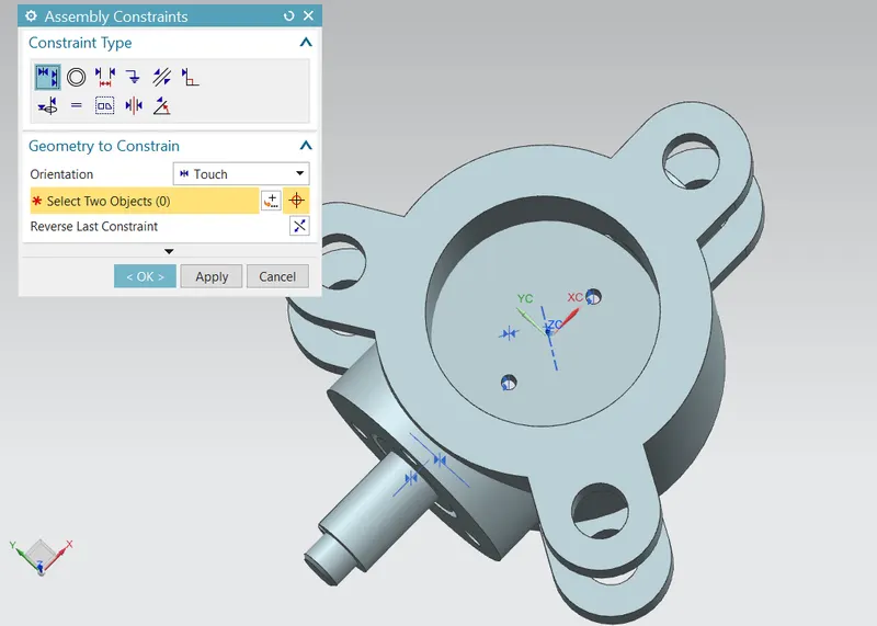
Fig. represents the disc plate DOF constrained by datum plane
(iii) Retainer
The retainer is constrained in all of its DOF. It has three datum features, one planar feature (datum plane), two cylindrical surfaces or hole features (datum axis). The datum plane constrains the retainer in 3 DOF - one translation - along x direction, two rotations - about z and y axes.
The second datum is an axis that constrains two translations - along z and y directions. The third datum is an axis that constrains one rotation - about x axis.
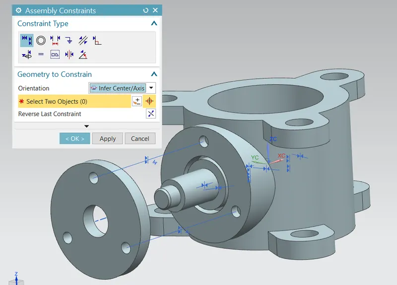
Fig. represents the retainer DOF constrained by datum axes
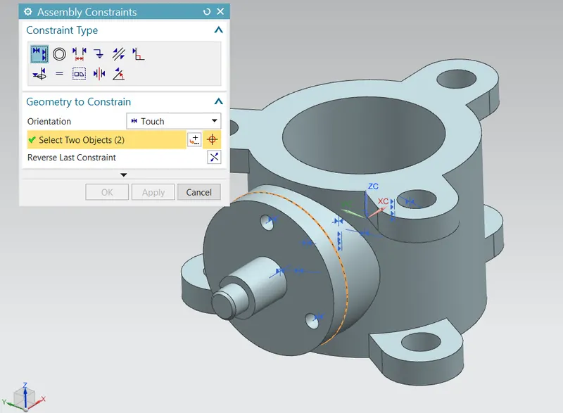
Fig. represents the retainer DOF constrained by datum plane
(iv) Lever
The lever is in its rotation about y and z axes - using a datum axis. and is constrained in translation along x axis - using a datum plane.
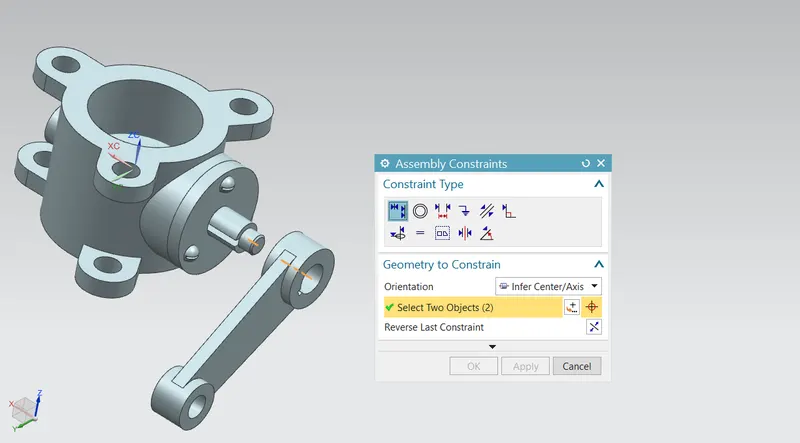
Fig. represents the lever DOF constrained by datum axis
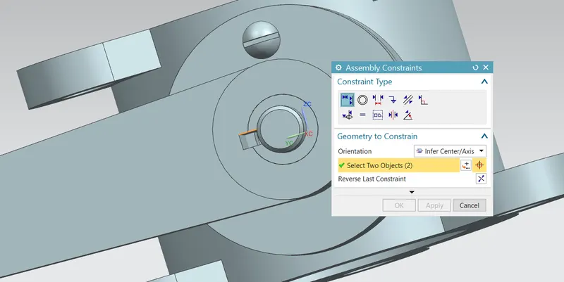
Fig. represents the lever DOF constrained by aligning its feature with shaft feature where the shaft key is placed. (DOF constained by datum plane)
(v) Nut
The nut is constrained in 5 DOF. It has two datum features, one planar feature (datum plane), one cylindrical surface or hole features (datum axis). The datum plane constrains the nut in 3 DOF - one translation - along x direction, two rotations - about z and y axes.
The second datum is an axis that constrains two translations - along z and y directions.
(vi) Screws
The screws are applied onto shaft and disc plate , and retainer and valve body to join or fasten the components.
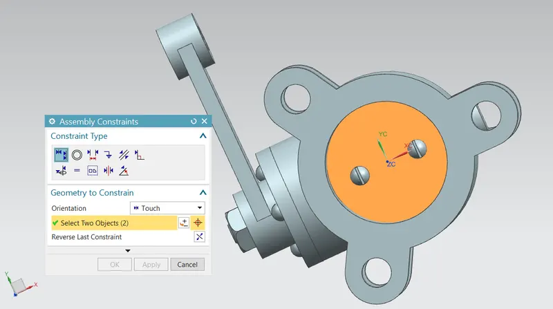
Fig. represents the screws applied to fasten disc plate to shaft
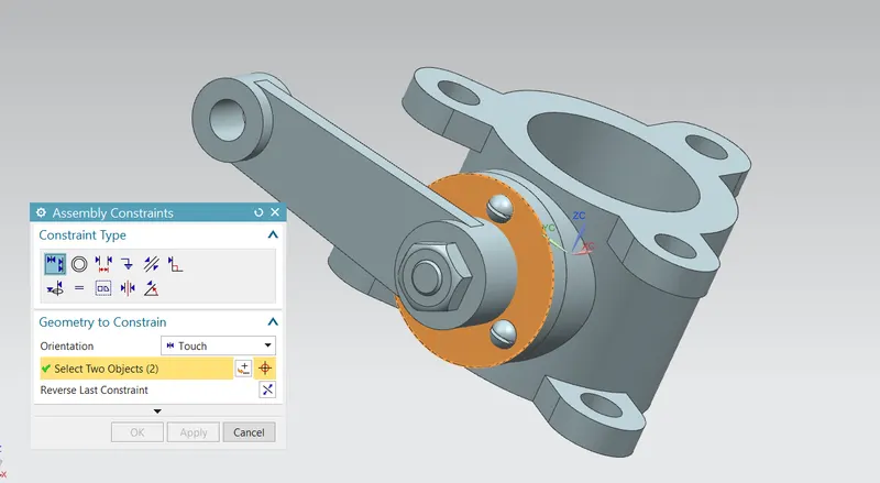
Fig. represents the screws applied to fasten retainer to valve body
Final Butterfly Valve Assembly
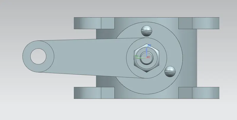
Isometric view
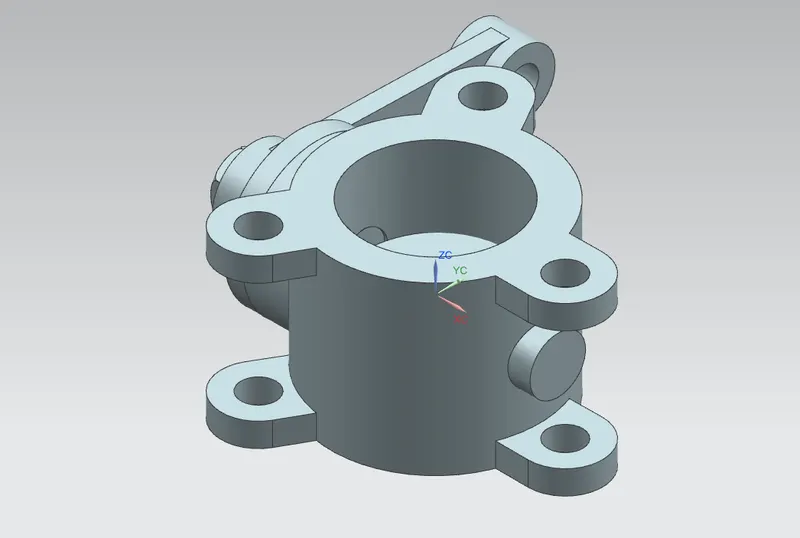
Top view
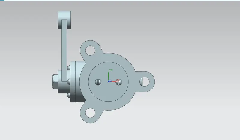
Front view
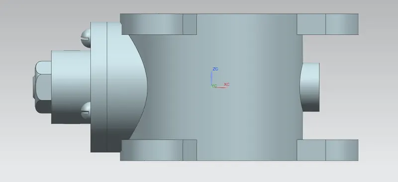
Side view
Application of GD&T Symbols on Drawing sheet
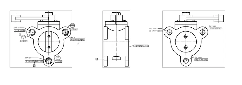
Explanation
Dimensional Size tolerances
All the features are provided with a tight tolerances of +/-0.1mm about their nominal sizes on side of the butterfly valve assembly i.e., at the location of datum features and +/-0.25 on other side flange to maintain tighter tolerances.
Location of Datum Reference Frames
The Butterfly valve assembly has 6 degrees of freedom, once it mates with the conduit or pipe on both sides, it must not be left with any degree of freedom.
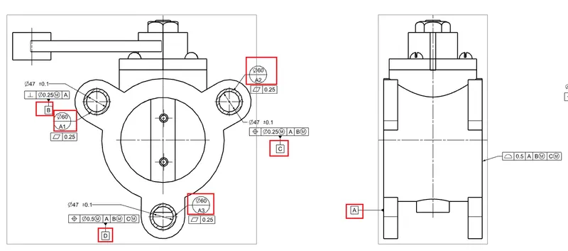
The primary datum A is established by datum target areas (for cost reduction purposes). The dtaum target areas are represented by A1,A2 and A3 with target areas of dia. 60mm as shown in above fig. The primary datum A forms a datum plane and it constrains the two rotations - about x and y axes, and one translation - along z direction.
The secondary datum B is a hole feature. This datum feature forms a datum axis which constrains 2 DOF of the butterfly valve assembly i.e., two translations - along x and y directions.
The teritiary datum C is a hole feature. This datum feature forms a datum axis which constrains 1 DOF of the butterfly valve assembly i.e., one rotation - about z axis.
Datum D is defined for axis control of the hole feature that is located at the opposite flange surface.
Geometric controls
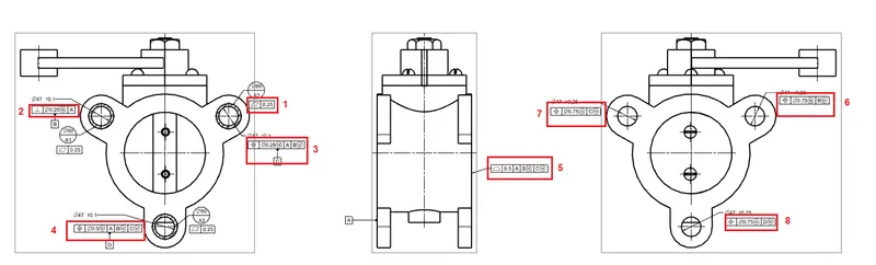
1 Flatness geometric tolerance (datum A)
A geometric control of flatness is applied onto the datum targets A1,A2 and A3 with a tolerance size of 0.25mm. ( the target area surfaces must lie within the tolerance zone of 0.25mm).
2 Perpendicularity geometric tolerance (datum B)
A geometric control of perpendicularity tolerance is applied onto the datum B with a tolerance size of 0.25mm at maximum material condition in relation to datum A. (the MMC modifier is applied to maintain tighter tolerance for the datum B, the tolerance zone (cylindrical) is perpendicluar to datum A and the feature or hole axis must lie with in this zone).
3 Position geometric tolerance (datum C)
A geometric control of position tolerance is applied onto the datum C with a tolerance size of 0.25mm at maximum material condition in relation to datum A and datum B at maximum material condition. (the MMC modifier is applied to maintain tighter tolerance for the datum C, feature or hole axis must lie with in the cylindrical zone 0.25mm dia.).
4 Position geometric tolerance (datum D)
A geometric control of position tolerance is applied onto the hole feature with a tolerance size of 0.5mm at maximum material condition in relation to datum A, datum B at maximum material condition & datum C at maximum material condition. (the MMC modifier is applied to maintain tighter tolerance for the feature, feature or hole axis must lie with in the cylindrical zone of 0.5mm dia.).
5 Profile geometric tolerance
A geometric control of profile of a surface is applied onto the surface with a tolerance size of 0.5mm at maximum material condition in relation to datum A, datum B at maximum material condition & datum C at maximum material condition. (to maintain proper thickness of the butterfly valve assembly, a profile tolerance is applied and the control implies that the surface profile must lie within the tolerance zone of 0.5mm).
AXIS CONTROL w.r.t datums B,C&D
The axes of the hole features on the other side of the flange are controlled by providing the tolerance zones w.r.t datums B,C and D to maintain coaxiality.
6 Position geometric tolerance
A geometric control of position tolerance is applied onto the hole feature with a tolerance size of 0.75mm at maximum material condition in relation to datum B at maximum material condition( this control maintains the coaxility of this hole feature w.r.t datum B).
7 Position geometric tolerance
A geometric control of position tolerance is applied onto the hole feature with a tolerance size of 0.75mm at maximum material condition in relation to datum C at maximum material condition( this control maintains the coaxility of this hole feature w.r.t datum C).
8 Position geometric tolerance
A geometric control of position tolerance is applied onto the hole feature with a tolerance size of 0.75mm at maximum material condition in relation to datum D at maximum material condition( this control maintains the coaxility of this hole feature w.r.t datum D).