Week 12 - Validation studies of Symmetry BC vs Wedge BC in OpenFOAM vs Analytical H.P equation
Objective :
- To write a Matlab code for symetry / wedge boundry condition of Axi-symetric simulation (Flow through the Pipe).
- To obtain the Results for the stimulation of the flow in the pipe with different wege angles (10,25 and 45)
- To compare the results of the simulation obtained from wedge and symetry boundry condition
- To plot the graph for the pressure profile , and calculate the pressure drop and verify with the analytical solution.
Theory :
Axi-symmetric flow : A Flow pattern is axisymmetric when it is identical in every plane that passes through a certain straight line . Every longitudinal plane through the axis would exhibhit the same streamline pattern.
Laminar Flow : In contrast to turbulent flow, in which the fluid undergoes unpredictable fluctuations and mixing, laminar flow is a type of fluid (gas or liquid) flow in which the fluid travels smoothly or in regular patterns. The velocity, pressure, and other flow parameters at each point in the fluid stay constant in laminar flow, also known as streamline flow. Laminar flow over a horizontal surface is made up of thin layers, or laminae, that are all parallel to one another.
Reynolds Number : The Reynolds number is the ratio of inertial forces to viscous forces within a fluid which is subjected to relative internal movement due to different fluid velocities. A region where these forces change behavior is known as a boundry layer, such as the bounding surface in the interior of a pipe.The Reynolds number is used to determine the relationship in fluid flow between inertial forces (those that keep the fluid moving according to Newton's first law - an object in motion stays in motion) and viscous forces (those that cause the fluid to come to a halt due to viscosity).
Proccedure :
To walk through this challenge we have to follow certain steps which are as follows :
1. Edit the previously made MATLAB code and the change the Input Boundry Condition (wedge/symetry ) for the BlockmeshDict file.
2. The wedge angle is given as an user defined input so the stimulation is run for the following wedge angles :
(i) `10^o`
(ii) `25^o`
(iii) `45^o`
3. The Initial condition like P and U are edited as required in the 0 Folder
4. The Transport property in the constant folder is edited as required
5. The Blockmesh command is run through the command line in Linux Terminal
6. The stimulation is run for 5 sec with a time step of 0.001 sec using the IcoFoam solver .
7. The preprocessing is done and the required plots are genrated and used for the detailed study of results.
Matlab code :
The code for Wedge Boundry Condition with an user defined wedge angle :
close all
clear all
clc
%% Inputs
% The Reynolds Number
Re = 2100
% The Diameter of the Pipe
D = input('Dia in mm : ');

% The Entry length of the Pipe
L = 0.06 * Re * D
L_p = L+ 0.7

% Radius of the Pipe
r = D/2
% Angle of wedge
teta = input('Enter value less than 5 Degrees : ')

% Dynamic viscosity
mu = 0.89e-3
% Density
rho  = 997

%% Haigen Poisle Flow Equation
v_avg = (Re*mu)/(rho*D)
v_max = 2*(v_avg)
del_p = (8*mu*L_p*v_avg)/(r^2)
ke_p = del_p/rho

%% Calculating the shear stress
R = linspace(0,r,1000);
for i = 1:length(R)
    tou(i) = 2*mu*v_max*(abs(R(i)))/r^2;
end
plot(R,tou)
xlabel('Radius')
ylabel('Shear stress')
grid on
legend('shear stress')

%% To create Mesh
% Vertices of the coordinates
v0 = [0 0 0]
v1 = [0 r*cosd(teta/2) r*sind(teta/2)]
v2 = [0 r*cosd(teta/2) -r*sind(teta/2)];
v3 = [L_p 0 0]
v4 = [L_p r*cosd(teta/2) r*sind(teta/2)]
v5 = [L_p r*cosd(teta/2) -r*sind(teta/2)]

%% Header Defination
h_1='/*--------------------------------*- C++ -*----------------------------------*\';
h_2='  =========                 |                                                    ';
h_3='  \\      /  F ield         | OpenFOAM: The Open Source CFD Toolbox            ';
h_4='   \\    /   O peration     | Website:  https://openfoam.org                   ';
h_5='    \\  /    A nd           | Version:  8                                      ';
h_6='     \\/     M anipulation  |                                                  ';
h_7='\*---------------------------------------------------------------------------*/';
h_8='FoamFile';
h_9='{';
h_10='  version     2.0;' ;
h_11='  format      ascii;';
h_12='  class       dictionary;';
h_13='  object      blockMeshDict;';
h_14='}';
h_15='// * * * * * * * * * * * * * * * * * * * * * * * * * * * * * * * * * * * * * //';

conv ='convertToMeters 1;';

f1 = fopen('blockMeshDict','wt') %% To open the text folder
%% Creating the Header files and comments
fprintf(f1,'%s\n',h_1);
fprintf(f1, '%s\n', h_2);
fprintf(f1, '%s\n', h_3);
fprintf(f1, '%s\n', h_4);
fprintf(f1, '%s\n', h_5);
fprintf(f1, '%s\n', h_6);
fprintf(f1, '%s\n', h_7);
fprintf(f1, '%s\n', h_8);
fprintf(f1, '%s\n', h_9);
fprintf(f1, '%s\n', h_10);
fprintf(f1, '%s\n', h_11);
fprintf(f1, '%s\n', h_12);
fprintf(f1, '%s\n', h_13);
fprintf(f1, '%s\n', h_14);
fprintf(f1, '%s\n\n', h_15);

fprintf(f1, '%s\n',conv);

fprintf(f1, 'vertices\n');
fprintf(f1, '(\n');
fprintf(f1, '\t(%d %d %d)\n',v0);
fprintf(f1, '\t(%d %d %d)\n',v1);
fprintf(f1, '\t(%d %d %d)\n',v2);
fprintf(f1, '\t(%d %d %d)\n',v3);
fprintf(f1, '\t(%d %d %d)\n',v4);
fprintf(f1, '\t(%d %d %d)\n',v5);
fprintf(f1, ');\n\n');

%% Blocks Defination
fprintf(f1, 'blocks\n');
fprintf(f1, '(\n');
fprintf(f1, '\t hex (0 3 5 2 0 3 4 1)(%d %d %d)',300,30,1);
fprintf(f1, ' SimpleGrading (1 0.1 1)\n\n');
fprintf(f1, ');\n\n');
%% Edges Defination
fprintf(f1, 'edges\n');
fprintf(f1, '(\n');
fprintf(f1, '\t arc %d %d (%d %d %d)\n',1,2,0,r,0);
fprintf(f1, '\t arc %d %d (%d %d %d)\n',4,5,L_p,r,0);
fprintf(f1, ');\n\n');
%% Inlet
fprintf(f1, 'boundry\n');
fprintf(f1, '(\n');
fprintf(f1, '\t inlet \n');
fprintf(f1, '\t {\n');
fprintf(f1, '\t\t type patch;\n');
fprintf(f1, '\t\t faces \n');
fprintf(f1, '\t\t (\n');
fprintf(f1, '\t\t\t (0 1 2 0)\n');
fprintf(f1, '\t\t );\n');
fprintf(f1, '\t }\n');
%% Outlet Defination
fprintf(f1, '\t outlet \n');
fprintf(f1, '\t {\n');
fprintf(f1, '\t\t type patch;\n');
fprintf(f1, '\t\t faces \n');
fprintf(f1, '\t\t (\n');
fprintf(f1, '\t\t\t (3 5 4 3)\n');
fprintf(f1, '\t\t );\n');
fprintf(f1, '\t }\n');
%% Top
fprintf(f1, '\t top \n');
fprintf(f1, '\t {\n');
fprintf(f1, '\t\t type wall;\n');
fprintf(f1, '\t\t faces \n');
fprintf(f1, '\t\t (\n');
fprintf(f1, '\t\t\t (1 4 5 2)\n');
fprintf(f1, '\t\t );\n');
fprintf(f1, '\t }\n');
%% Front
fprintf(f1, '\t front \n');
fprintf(f1, '\t {\n');
fprintf(f1, '\t\t type wedge;\n');
fprintf(f1, '\t\t faces \n');
fprintf(f1, '\t\t (\n');
fprintf(f1, '\t\t\t (0 3 4 1)\n');
fprintf(f1, '\t\t );\n');
fprintf(f1, '\t }\n');
%% Back
fprintf(f1, '\t back \n');
fprintf(f1, '\t {\n');
fprintf(f1, '\t\t type wedge;\n');
fprintf(f1, '\t\t faces \n');
fprintf(f1, '\t\t (\n');
fprintf(f1, '\t\t\t (0 2 5 3)\n');
fprintf(f1, '\t\t );\n');
fprintf(f1, '\t }\n');
%% Axis
fprintf(f1, '\t axis \n');
fprintf(f1, '\t {\n');
fprintf(f1, '\t\t type empty;\n');
fprintf(f1, '\t\t faces \n');
fprintf(f1, '\t\t (\n');
fprintf(f1, '\t\t\t (0 3 3 0)\n');
fprintf(f1, '\t\t );\n');
fprintf(f1, '\t }\n');
fprintf(f1, '); \n\n');

fprintf(f1, 'mergePatchPairs\n');
fprintf(f1, '(\n');
fprintf(f1, ');\n');

h_17='//***********************************************************************//';
fprintf(f1, '%s\n',h_17);

fclose(f1);

%%
Fig 1 : Matlab code with wedge Boundry condition
close all
clear all
clc
%% Inputs
% The Reynolds Number
Re = 2100
% The Diameter of the Pipe
D = input('Dia in mm : ');

% The Entry length of the Pipe
L = 0.06 * Re * D
L_p = L+ 0.7

% Radius of the Pipe
r = D/2
% Angle of wedge
teta = input('Enter wedge angle : ')

% Dynamic viscosity
mu = 0.89e-3
% Density
rho  = 997

%% Haigen Poisle Flow Equation
v_avg = (Re*mu)/(rho*D)
v_max = 2*(v_avg)
del_p = (8*mu*L_p*v_avg)/(r^2)
ke_p = del_p/rho

%% Calculating the shear stress
R = linspace(0,r,1000);
for i = 1:length(R)
    tou(i) = 2*mu*v_max*(abs(R(i)))/r^2;
end
plot(R,tou)
xlabel('Radius')
ylabel('Shear stress')
grid on
legend('shear stress')

%% To create Mesh
% Vertices of the coordinates
v0 = [0 0 0]
v1 = [0 r*cosd(teta/2) r*sind(teta/2)]
v2 = [0 r*cosd(teta/2) -r*sind(teta/2)];
v3 = [L_p 0 0]
v4 = [L_p r*cosd(teta/2) r*sind(teta/2)]
v5 = [L_p r*cosd(teta/2) -r*sind(teta/2)]

%% Header Defination
h_1='/*--------------------------------*- C++ -*----------------------------------*\';
h_2='  =========                 |                                                    ';
h_3='  \\      /  F ield         | OpenFOAM: The Open Source CFD Toolbox            ';
h_4='   \\    /   O peration     | Website:  https://openfoam.org                   ';
h_5='    \\  /    A nd           | Version:  8                                      ';
h_6='     \\/     M anipulation  |                                                  ';
h_7='\*---------------------------------------------------------------------------*/';
h_8='FoamFile';
h_9='{';
h_10='  version     2.0;' ;
h_11='  format      ascii;';
h_12='  class       dictionary;';
h_13='  object      blockMeshDict;';
h_14='}';
h_15='// * * * * * * * * * * * * * * * * * * * * * * * * * * * * * * * * * * * * * //';

conv ='convertToMeters 1;';

f1 = fopen('blockMeshDict','wt') %% To open the text folder
%% Creating the Header files and comments
fprintf(f1,'%s\n',h_1);
fprintf(f1, '%s\n', h_2);
fprintf(f1, '%s\n', h_3);
fprintf(f1, '%s\n', h_4);
fprintf(f1, '%s\n', h_5);
fprintf(f1, '%s\n', h_6);
fprintf(f1, '%s\n', h_7);
fprintf(f1, '%s\n', h_8);
fprintf(f1, '%s\n', h_9);
fprintf(f1, '%s\n', h_10);
fprintf(f1, '%s\n', h_11);
fprintf(f1, '%s\n', h_12);
fprintf(f1, '%s\n', h_13);
fprintf(f1, '%s\n', h_14);
fprintf(f1, '%s\n\n', h_15);

fprintf(f1, '%s\n',conv);

fprintf(f1, 'vertices\n');
fprintf(f1, '(\n');
fprintf(f1, '\t(%d %d %d)\n',v0);
fprintf(f1, '\t(%d %d %d)\n',v1);
fprintf(f1, '\t(%d %d %d)\n',v2);
fprintf(f1, '\t(%d %d %d)\n',v3);
fprintf(f1, '\t(%d %d %d)\n',v4);
fprintf(f1, '\t(%d %d %d)\n',v5);
fprintf(f1, ');\n\n');

%% Blocks Defination
fprintf(f1, 'blocks\n');
fprintf(f1, '(\n');
fprintf(f1, '\t hex (0 3 5 2 0 3 4 1)(%d %d %d)',300,30,1);
fprintf(f1, ' SimpleGrading (1 0.1 1)\n\n');
fprintf(f1, ');\n\n');
%% Edges Defination
fprintf(f1, 'edges\n');
fprintf(f1, '(\n');
fprintf(f1, '\t arc %d %d (%d %d %d)\n',1,2,0,r,0);
fprintf(f1, '\t arc %d %d (%d %d %d)\n',4,5,L_p,r,0);
fprintf(f1, ');\n\n');
%% Inlet
fprintf(f1, 'boundry\n');
fprintf(f1, '(\n');
fprintf(f1, '\t inlet \n');
fprintf(f1, '\t {\n');
fprintf(f1, '\t\t type patch;\n');
fprintf(f1, '\t\t faces \n');
fprintf(f1, '\t\t (\n');
fprintf(f1, '\t\t\t (0 1 2 0)\n');
fprintf(f1, '\t\t );\n');
fprintf(f1, '\t }\n');
%% Outlet Defination
fprintf(f1, '\t outlet \n');
fprintf(f1, '\t {\n');
fprintf(f1, '\t\t type patch;\n');
fprintf(f1, '\t\t faces \n');
fprintf(f1, '\t\t (\n');
fprintf(f1, '\t\t\t (3 5 4 3)\n');
fprintf(f1, '\t\t );\n');
fprintf(f1, '\t }\n');
%% Top
fprintf(f1, '\t top \n');
fprintf(f1, '\t {\n');
fprintf(f1, '\t\t type wall;\n');
fprintf(f1, '\t\t faces \n');
fprintf(f1, '\t\t (\n');
fprintf(f1, '\t\t\t (1 4 5 2)\n');
fprintf(f1, '\t\t );\n');
fprintf(f1, '\t }\n');
%% Front (symmetry Boundry condition)
fprintf(f1, '\t front_wedge \n');
fprintf(f1, '\t {\n');
fprintf(f1, '\t\t type symmetry;\n');
fprintf(f1, '\t\t faces \n');
fprintf(f1, '\t\t (\n');
fprintf(f1, '\t\t\t (0 3 4 1)\n');
fprintf(f1, '\t\t );\n');
fprintf(f1, '\t }\n');
%% Back (symmetry Boundry condition)
fprintf(f1, '\t back_wedge \n');
fprintf(f1, '\t {\n');
fprintf(f1, '\t\t type symmetry;\n');
fprintf(f1, '\t\t faces \n');
fprintf(f1, '\t\t (\n');
fprintf(f1, '\t\t\t (0 2 5 3)\n');
fprintf(f1, '\t\t );\n');
fprintf(f1, '\t }\n');
%% Axis
fprintf(f1, '\t axis \n');
fprintf(f1, '\t {\n');
fprintf(f1, '\t\t type empty;\n');
fprintf(f1, '\t\t faces \n');
fprintf(f1, '\t\t (\n');
fprintf(f1, '\t\t\t (0 3 3 0)\n');
fprintf(f1, '\t\t );\n');
fprintf(f1, '\t }\n');
fprintf(f1, '); \n\n');

fprintf(f1, 'mergePatchPairs\n');
fprintf(f1, '(\n');
fprintf(f1, ');\n');

h_17='//***********************************************************************//';
fprintf(f1, '%s\n',h_17);

fclose(f1);
Fig 2 : Symetry Boundry condition
BlockMeshDict File :
Wedge Boundry Condition (user Defined wedge `10^o`) :
/*--------------------------------*- C++ -*----------------------------------*\
  =========                 |
  \\      /  F ield         | OpenFOAM: The Open Source CFD Toolbox
   \\    /   O peration     | Website:  https://openfoam.org
    \\  /    A nd           | Version:  8
     \\/     M anipulation  |
\*---------------------------------------------------------------------------*/
FoamFile
{
    version     2.0;
    format      ascii;
    class       dictionary;
    object      blockMeshDict;
}
// * * * * * * * * * * * * * * * * * * * * * * * * * * * * * * * * * * * * * //

convertToMeters 1;

vertices
(
    // 1st Face set

    (0 0 0)             //0
    (0 1.992389e-03 1.743115e-04)          //1
    (0 1.992389e-03 -1.743115e-04)         //2
    (1.204000e+00 0 0)       //3
    (1.204000e+00 1.992389e-03 1.743115e-04)          //4
    (1.204000e+00 1.992389e-03 -1.743115e-04)        //5


);

blocks
(
    hex (0 3 5 2 0 3 4 1)(300 30 1) SimpleGrading (1 0.1 1)


);

edges
(
     arc 1 2 (0 2.000000e-03 0)
     arc 4 5 (1.204000e+00 2.000000e-03 0)
);

boundary
(
    inlet
    {
        type patch;
        faces
        (
            (0 1 2 0)

        );
    }
    outlet
    {
        type patch;
        faces
        (
            (3 5 4 3)

        );
    }

    top
    {
        type wall;
        faces
        (
            (1 4 5 2)


        );
    }

    front
    {
        type wedge;
        faces
        (
            (0 3 4 1)


        );
    }

    back_wedge
    {
        type wedge;
        faces
        (
            (0 2 5 3)


        );
    }

    axis
    {
        type empty;
        faces
        (
            (0 3 3 0)


        );
    }

);

mergePatchPairs
(

);

//***********************************************************************//
Fig 3 : BlockMeshDict (wedge `10^o` , Wedge Boundry condition)
Symmetry Boundry Condition (user Defined wedge `10^o`) :
/*--------------------------------*- C++ -*----------------------------------*\
  =========                 |
  \\      /  F ield         | OpenFOAM: The Open Source CFD Toolbox
   \\    /   O peration     | Website:  https://openfoam.org
    \\  /    A nd           | Version:  8
     \\/     M anipulation  |
\*---------------------------------------------------------------------------*/
FoamFile
{
    version     2.0;
    format      ascii;
    class       dictionary;
    object      blockMeshDict;
}
// * * * * * * * * * * * * * * * * * * * * * * * * * * * * * * * * * * * * * //

convertToMeters 1;

vertices
(
    // 1st Face set

    (0 0 0)             //0
    (0 1.992389e-03 1.743115e-04)          //1
    (0 1.992389e-03 -1.743115e-04)         //2
    (1.204000e+00 0 0)       //3
    (1.204000e+00 1.992389e-03 1.743115e-04)          //4
    (1.204000e+00 1.992389e-03 -1.743115e-04)        //5


);

blocks
(
    hex (0 3 5 2 0 3 4 1)(300 30 1) SimpleGrading (1 0.1 1)


);

edges
(
     arc 1 2 (0 2.000000e-03 0)
     arc 4 5 (1.204000e+00 2.000000e-03 0)
);

boundary
(
    inlet
    {
        type patch;
        faces
        (
            (0 1 2 0)

        );
    }
    outlet
    {
        type patch;
        faces
        (
            (3 5 4 3)

        );
    }

    top
    {
        type wall;
        faces
        (
            (1 4 5 2)


        );
    }

    front_wedge
    {
        type symmetry;
        faces
        (
            (0 3 4 1)


        );
    }

    back_wedge
    {
        type symmetry;
        faces
        (
            (0 2 5 3)


        );
    }

    axis
    {
        type empty;
        faces
        (
            (0 3 3 0)


        );
    }

);

mergePatchPairs
(

);

//***********************************************************************//
Fig 4 : BlockMeshDict (wedge `10^o` , Symmetry Boundry condition)
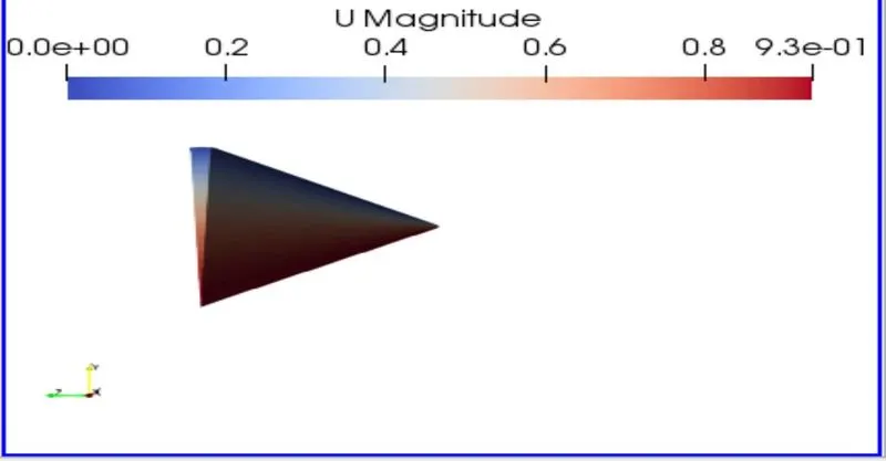
Fig 5 : wedge Angle 10 degree
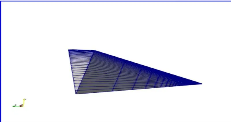
Fig 6: Wedge Angle 25 degrees
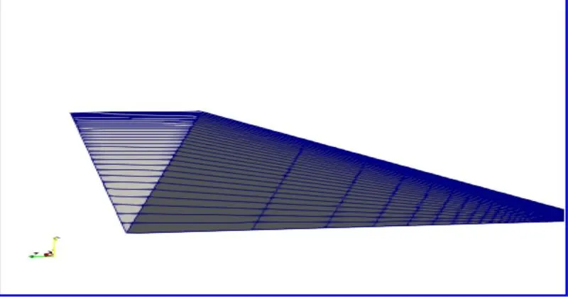
Fig 7: Wedge Angle 45 degrees
Results and comparrision
SHEAR STRESS :
wedge Angle ( `10^o`):
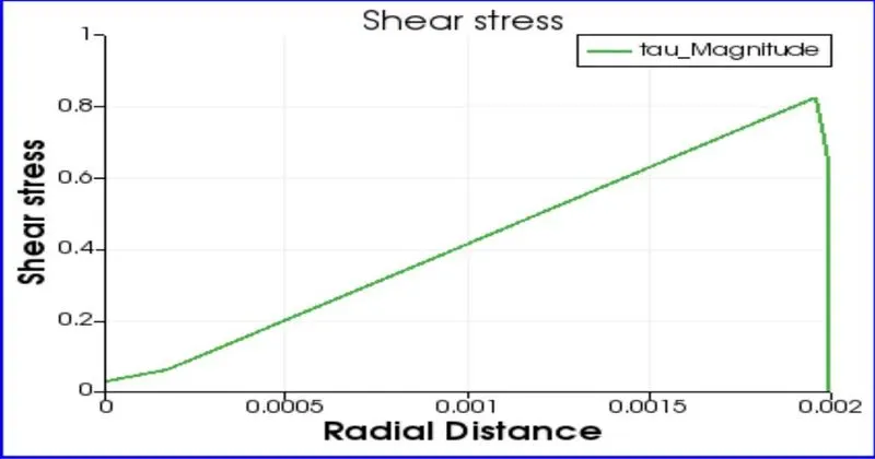
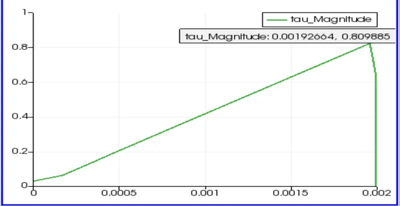
Fig 8 : shear stress shymetry boundy condition Fig 9: shear stress wedge boundry condition
The shear stress plot for both the boundry conditions, the wedge boundry condition and the symmetry boundry condition and the symmetry condition are shown at 10 degrees. We can see that when we apply the symmetry boundry condition , the slope of the curve is much higher than we apply the wedge boundry condition. So , when we apply the symmetry boundry condition , the mesh becomes 3D and the computation is done for all three global axis. This affects the calculation as well , the peak value in the wedge boundry condition is approximateley 0.809 units where as in the symmetry boundry condition the peak value touches arround 0.756 units.
wedge Angle ( `25^o`):
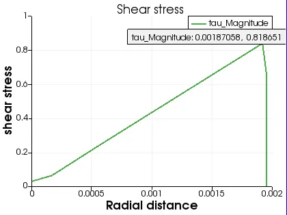
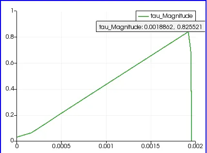
Fig 10 : shear stress shymetry boundy condition Fig 11: shear stress wedge boundry condition
The graph shown above is comparing the shear stress for both boundry condition with a wedge angle of 25 degrees.
wedge Angle ( `45^o`):
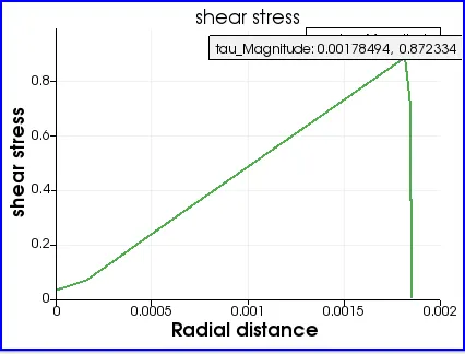
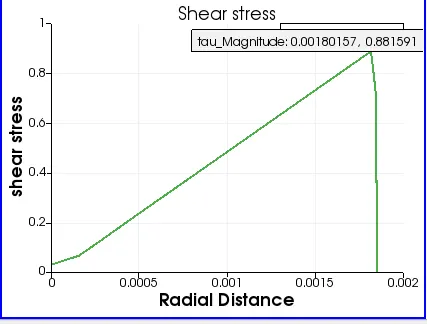
Fig 12 : shear stress shymetry boundy condition Fig 13: shear stress wedge boundry condition
The Graph compares the shear stress at 45 Deg for both the boundry conditions.
VELOCITY :
Wedge Angle ( `10^o`):
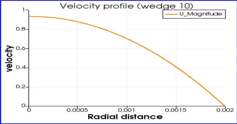
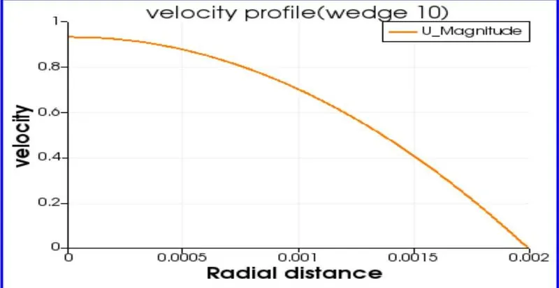
Fig 14 : Velocity profile symetry boundy condition Fig 15: Velocity profile wedge boundy condition
Wedge Angle ( `25^o`):
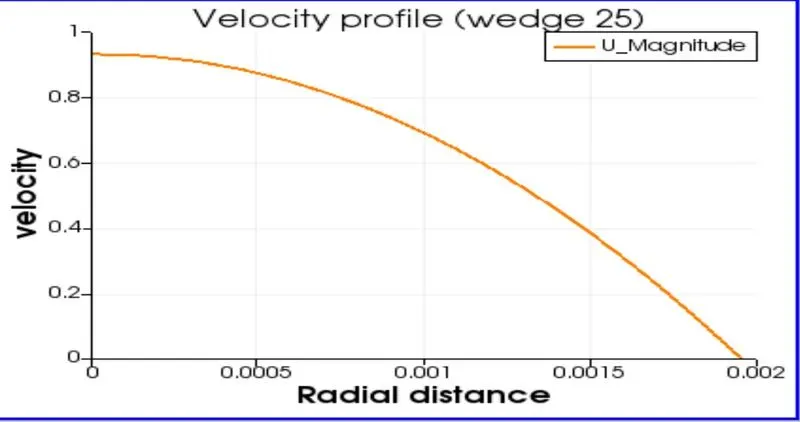
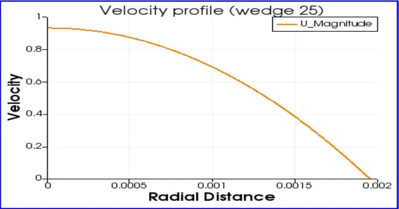
Fig 16 : Velocity profile symetry boundy condition Fig 17: Velocity profile wedge boundy condition
Wedge Angle ( `45^o`):
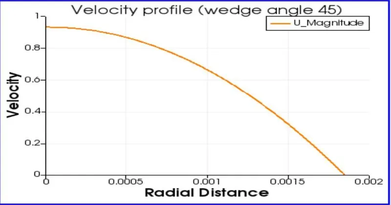
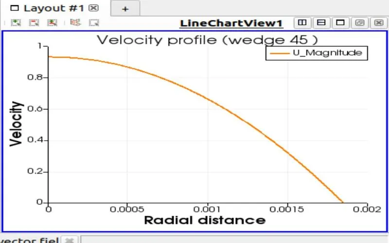
Fig 18 : Velocity profile symetry boundy condition Fig 19: Velocity profile wedge boundy condition
Validation :
Validation of Maximum pressure drop in the Fully developed Region
This graph depicts the change in the various parametres for both the Boundry condition and we cacan compare these quantities properly.
In this section we compare the pressure drop from the graph and the pressure drop value we get analytically.
The pressure drop can be calculated from the given formula :
`triangle P = (8*V_(avg)*mu*L)/r^2`
`V_(avg) = 0.4687`
`mu = 0.00089`
`L = L_p +0.7`
`D = 0.004`
`r = 0.002`
`triangle P =` 583.876 Pa (Is the pressure drop value obtained Annalytically)
Wedge Angle ( `45^o`):
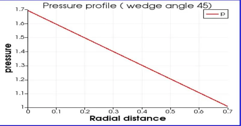
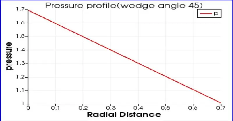
Fig 20 : Pressure profile symetry boundy condition Fig 21: Pressure profile wedge boundy condition
Wedge Angle ( `25^o`):
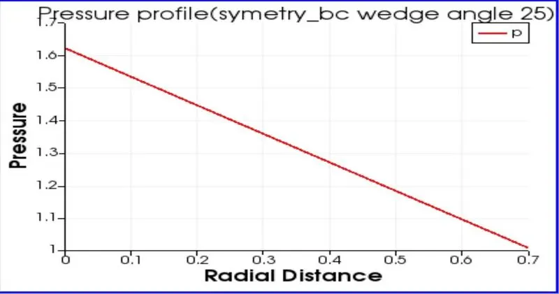
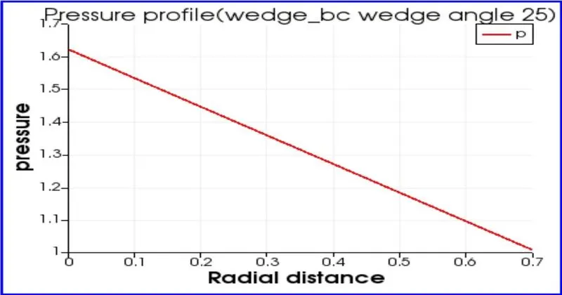
Fig 22 : Pressure profile symetry boundy condition Fig 23: Pressure profile wedge boundy condition
Wedge Angle ( `10^o`):
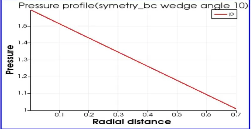
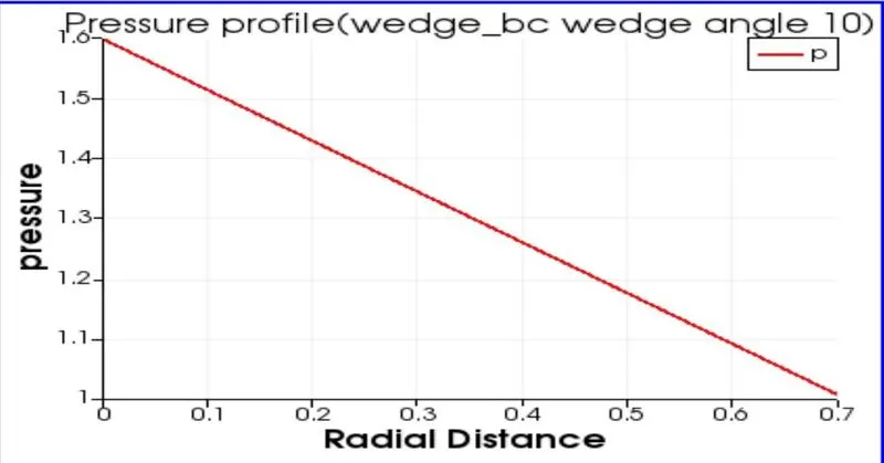
Fig 24 : Pressure profile symetry boundy condition Fig 25: Pressure profile wedge boundy condition
Pressure drop Validation :
| wedge Angle | symmetry BC (pa) | Wedge BC (pa) | Analytical | Error Percentage (symmetry_BC) | Error Percentage (Wedge_BC) | |||
| `10^o` |
|
|
|
1.208 % | 1.208 % | |||
| `25^0` |
|
|
|
5.333 % | 5.332 % | |||
| `45^0` |
|
|
|
17.528 % | 17.528 % |
from the Stimulations we can conclude that :
1. The pressure drop error increases as the wedge angle increases
2. Symmetry BC is more accurate than the wedge BC
3. Stimulation time is greater in wedge condition than symmetry condition