Week 12 - Validation studies of Symmetry BC vs Wedge BC in OpenFOAM vs Analytical H.P equation
AIM: To simulate laminar flow through pipe having constant cross-section using symmetry boundary condition by taking the wedge angle
as 10deg,25deg and 45deg and also comparing it with wedge boundary condition.
Expected Results
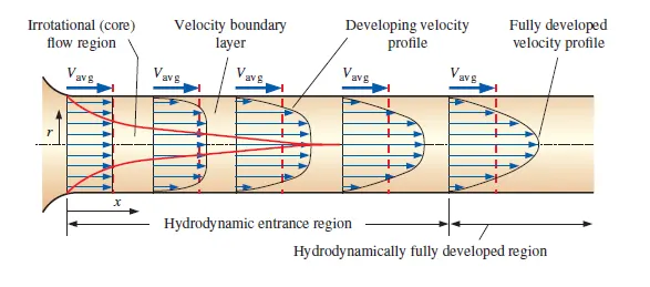
- To validate Hydro-dynamic length with the numerical result
- To validate the fully developed flow velocity profile with its analytical profile
- To validate maximum velocity and pressured drop for fully developed flow
- To post-process Shear stress and validate wall shear stress for fully developed flow
- Highlight the differences in both boundary conditions in terms of their usage and application
flow through pipe
10deg wedge angle with wedge boundary condition
blockMeshDict
/*-------------------------------*- C++--------------------------------*
===========                 |
\\       /    F ield        | OpenFOAM: The Open Source CFD Tool Box
 \\     /     O peration    | Website:  http:// openfoam.org
  \\   /      A nd          | Version   8
   \\ /       M anipulation |
\*----------------------------------------------------------------------------*/
FoamFile
{
	format   ascii;
	class    dictionary;
	object   blockMeshDict;
}

//* * * * * * * * * * * * * * * * * * * * * *  * * * * * *  * * * * * * //
convertToMeters 1;
vertices
 (
	 (0 0 0)
	 (0 7.471460e-03 6.536681e-04)
         (0 7.471460e-03 -6.536681e-04)
	 (2.190000e+00 0 0)
	 (2.190000e+00 7.471460e-03 6.536681e-04)
	 (2.190000e+00 7.471460e-03 -6.536681e-04)
);

blocks
(
	 hex (0 3 5 2 0 3 4 1 ) (300 20 1) SimpleGrading (1 0.1 1)

);

edges
(
	 arc 1 2 (0 7.500000e-03 0)
	 arc 4 5 (2.190000e+00 7.500000e-03 0)
);

boundary
(
	 axis
	{
		 type empty;
		 Faces
		(
		 (0 3 3 0)
		);
	}
	 wall
	{
		 type wall;
		 Faces
		(
		 (2 5 4 1)
		);
	}
	 inlet
	{
		 type patch;
		 Faces
		(
		 (0 1 2 0)
		);
	}
	 outlet
	{
		 type patch;
		 Faces
		(
		 (3 5 4 3)
		);
	}
	 front
	{
		 type wedge;
		 Faces
		(
		 (0 3 4 1)
		);
	}
	 back
	{
		 type wedge;
		 Faces
		(
		 (3 0 2 5)
		);
	}
)
mergePatchPair
(
);
//***********************************************//
25deg wedge angle with wedge boundary condition
blockMeshDict
/*--------------------------------*- C++ -*----------------------------------*\
  =========                 |
  \\      /  F ield         | OpenFOAM: The Open Source CFD Toolbox
   \\    /   O peration     | Website:  https://openfoam.org
    \\  /    A nd           | Version:  8
     \\/     M anipulation  |
\*---------------------------------------------------------------------------*/
FoamFile
{
    version     2.0;
    format      ascii;
    class       dictionary;
    object      blockMeshDict;
}
// * * * * * * * * * * * * * * * * * * * * * * * * * * * * * * * * * * * * * //

convertToMeters 1;

vertices
(
    (0 0 0)
    (0 7.322220e-03 1.623297e-03)
    (0 7.322220e-03 -1.623297e-03)
    (2.190000e+00 0 0)
    (2.190000e+00 7.322220e-03 1.623297e-03)
    (2.190000e+00 7.322220e-03 -1.623297e-03)
);

blocks
(
    hex (0 3 5 2 0 3 4 1) (300 50 1) simpleGrading (1 0.1 1)
);

edges
(
    arc 1 2 (0 7.500000e-03 0)
    arc 4 5 (2.190000e+00 7.500000e-03 0)
);

boundary
(
    axis
    {
        type empty;
        faces
        (
            (0 3 3 0)
        );
    }
    inlet
    {
        type patch;
        faces
        (
            (0 1 2 0)
        );
    }
    outlet
    {
        type patch;
        faces
        (
            (3 5 4 3)
        );
    }
    topWall
    {
        type wall;
        faces
        (
            (1 4 5 2)
        );
    }
    front
    {
        type wedge;
        faces
        (
            (0 3 4 1)
        );
    }
    back
    {
        type wedge;
        faces
        (
            (3 0 2 5)
        );
    }
);

mergePatchPairs
(
);

// ************************************************************************* //
45deg wedge angle with wedge boundary condition
blockMeshDict
/*--------------------------------*- C++ -*----------------------------------*\
  =========                 |
  \\      /  F ield         | OpenFOAM: The Open Source CFD Toolbox
   \\    /   O peration     | Website:  https://openfoam.org
    \\  /    A nd           | Version:  8
     \\/     M anipulation  |
\*---------------------------------------------------------------------------*/
FoamFile
{
    version     2.0;
    format      ascii;
    class       dictionary;
    object      blockMeshDict;
}
// * * * * * * * * * * * * * * * * * * * * * * * * * * * * * * * * * * * * * //

convertToMeters 1;

vertices
(
    (0 0 0)
    (0 6.929096e-03 2.870126e-03)
    (0 6.929096e-03 -2.870126e-03)
    (2.190000e+00 0 0)
    (2.190000e+00 6.929096e-03 2.870126e-03)
    (2.190000e+00 6.929096e-03 -2.870126e-03)
);

blocks
(
    hex (0 3 5 2 0 3 4 1) (300 50 1) simpleGrading (1 0.1 1)
);

edges
(
    arc 1 2 (0 7.500000e-03 0)
    arc 4 5 (2.190000e+00 7.500000e-03 0)
);

boundary
(
    axis
    {
        type empty;
        faces
        (
            (0 3 3 0)
        );
    }
    inlet
    {
        type patch;
        faces
        (
            (0 1 2 0)
        );
    }
    outlet
    {
        type patch;
        faces
        (
            (3 5 4 3)
        );
    }
    topWall
    {
        type wall;
        faces
        (
            (1 4 5 2)
        );
    }
    front
    {
        type wedge;
        faces
        (
            (0 3 4 1)
        );
    }
    back
    {
        type wedge;
        faces
        (
            (3 0 2 5)
        );
    }
);

mergePatchPairs
(
);

// ************************************************************************* //
Results
plots for wedge boundary condition
10deg
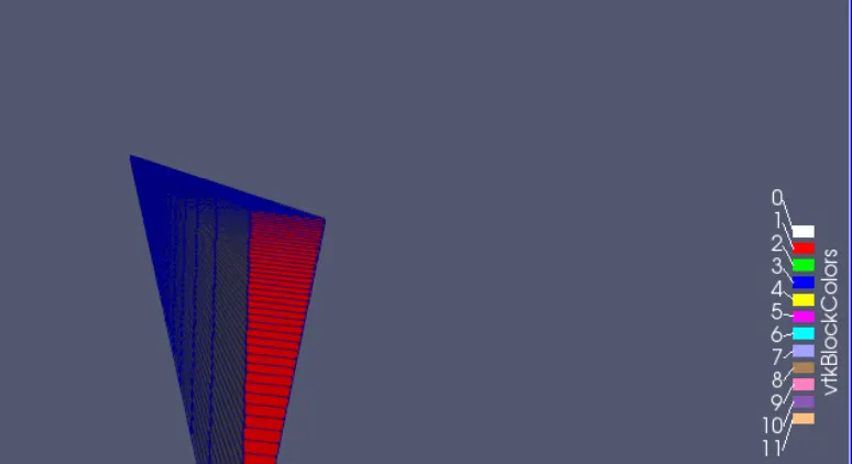
Fig.1 mesh profile
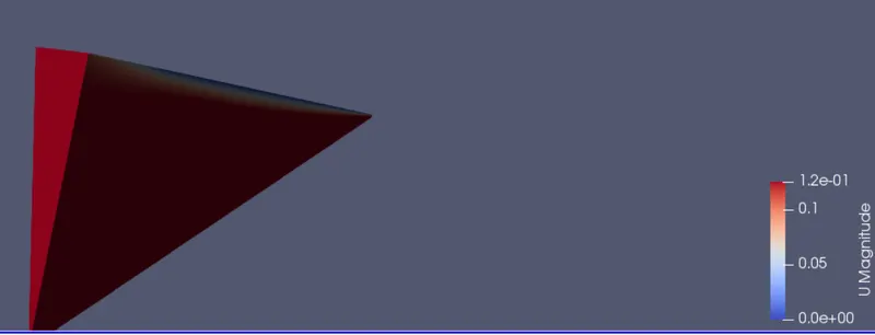
Fig.2 velocity profile
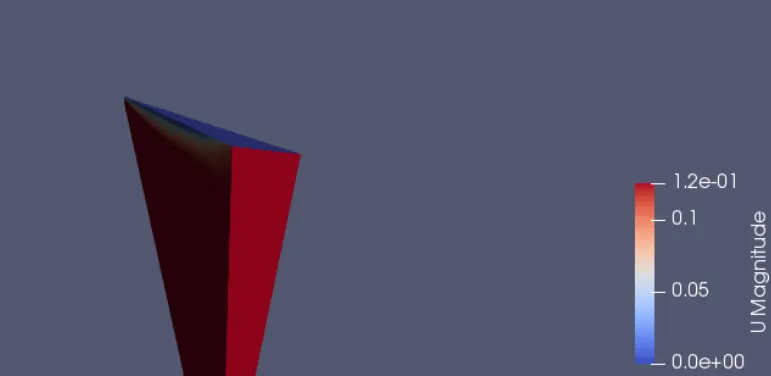
Fig.3 velocity profie
25 degree
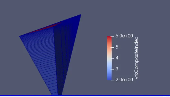
Fig.4 mesh grid
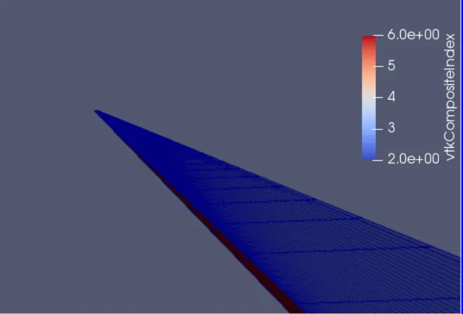
Fig.5 mesh grid
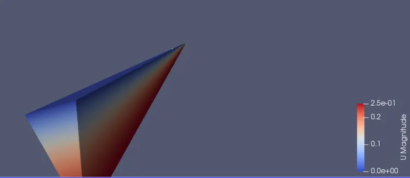
Fig.6 velocity profile
45 degree
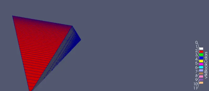
Fig.7 mesh grid
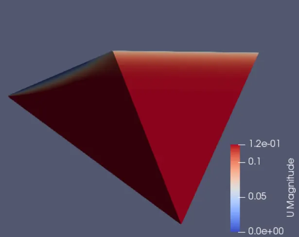
Fig.8 velocity profile
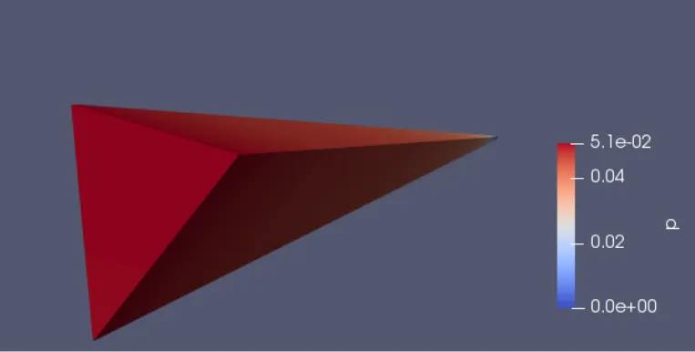
Fig.9 pressure profile
graphs for wedge boundary condition
10 degree
0.5m from pipe inlet,v_max=0.215258m/s
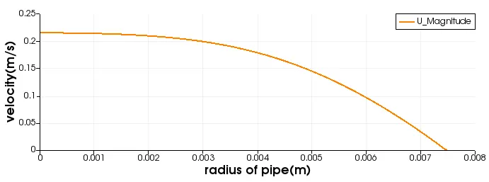
Fig.10 variation of velocity(Y-axis) vs radius of pipe(X-axis) at a particular location
10deg 1.0m from pipe inlet, V_max=0.23757m/s
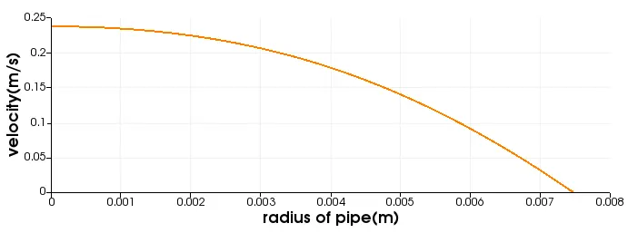
Fig.11 variation of velocity(Y-axis) vs radius of pipe(X-axis) at a particular location
10deg 1.5m from pipe inlet,V_max=0.245058m/s
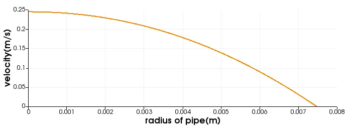
Fig.12 variation of velocity(Y-axis) vs radius of pipe(X-axis) at a particular location
10deg 1.89m from pipe inlet, V_max=0.247031m/s
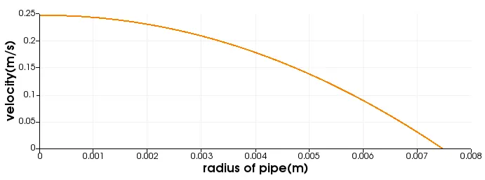
Fig.13 variation of velocity(Y-axis) vs radius of pipe(X-axis) at a particular location
10deg
2.0m from pipe inlet,V_max=0.247649m/s
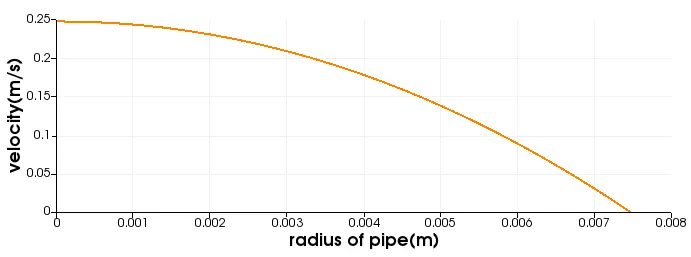
Fig. 14 variation of velocity(Y-axis) vs radius of pipe(X-axis) at a particular location
10deg
P_max=
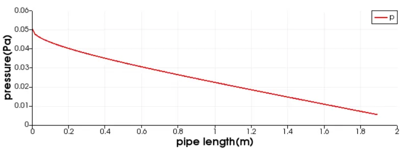
Fig.15 variation of pressure vs length of pipe(m)
10deg
tau_max= 0.063006 N/m^2
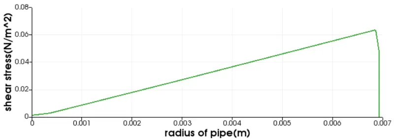
Fig. 16
25 degree
0.5m from pipe inlet, V_max=0.215212m/s
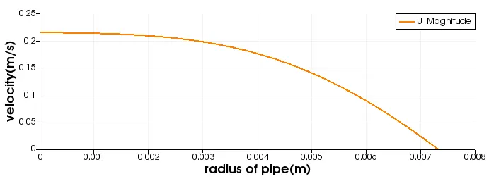
Fig.17 variation of velocity(Y-axis) vs radius of pipe(X-axis) at a particular location
25 deg
1.5m from pipe inlet, V_max=0.244872m/s
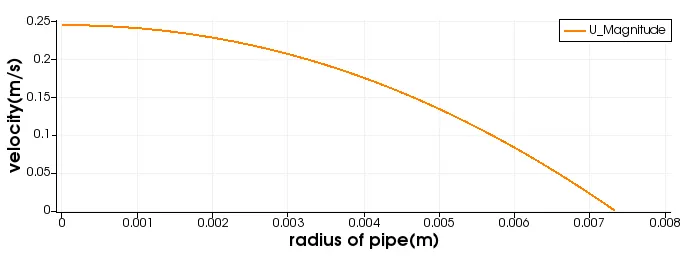
Fig.18 variation of velocity(Y-axis) vs radius of pipe(X-axis) at a particular location
25deg
1.6m from pipe inlet, V_max=0.245625m/s
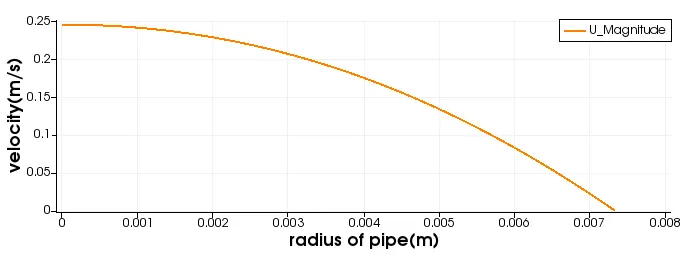
Fig.19 variation of velocity(Y-axis) vs radius of pipe(X-axis) at a particular location
25deg
1.8m from pipe inlet, V_max=0.246658m/s
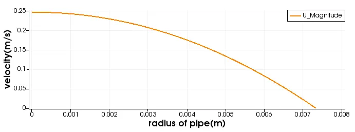
Fig.20 variation of velocity(Y-axis) vs radius of pipe(X-axis) at a particular location
25deg
2.0m from pipe inlet, V_max=0.247649m/s
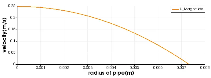
Fig.21 variation of velocity(Y-axis) vs radius of pipe(X-axis) at a particular location
25deg
p_at 1.89m from inlet=0.005583 Pa
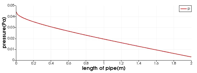
Fig.22 variation of pressure along length of pipe
25deg
tau_max=0.063396N/m^2
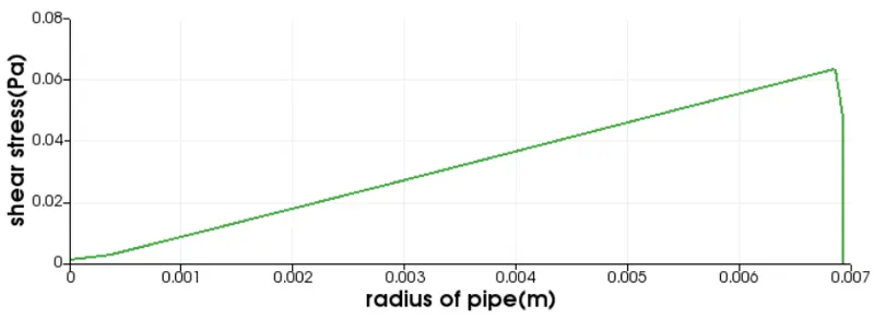
Fig.23
45 degree
0.5m from pipe inlet, V_max=0.215158m/s
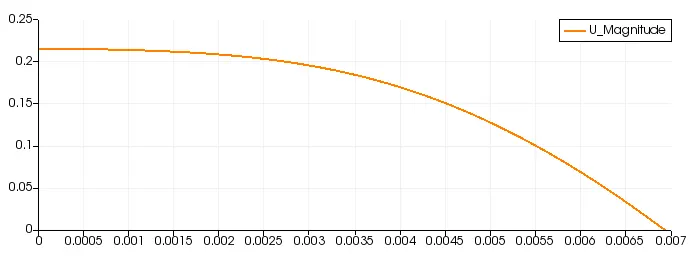
Fig.24 variation of velocity(Y-axis) vs radius of pipe(X-axis) at a particular location
45deg
1.0m from pipe inlet, V_max=0.237359m/s
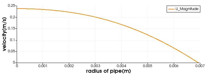
Fig.25 variation of velocity(Y-axis) vs radius of pipe(X-axis) at a particular location
45deg
1.5m from pipe inlet, V_max= 0.245058m/s
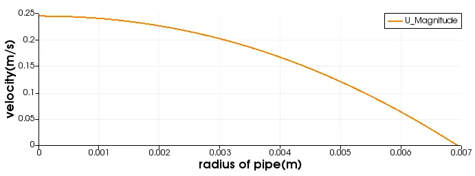
Fig.26 variation of velocity(Y-axis) vs radius of pipe(X-axis) at a particular location
45deg
1.7m from pipe inlet, V_max=0.246417m/s
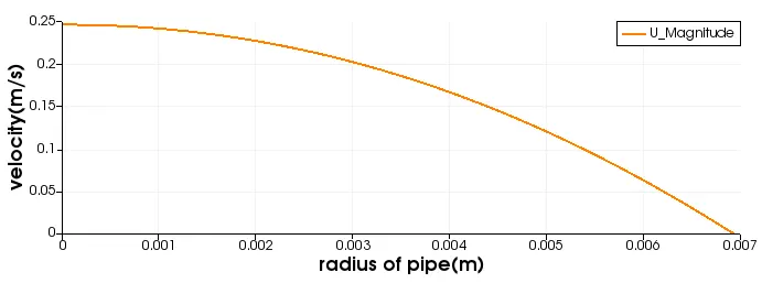
Fig.27 variation of velocity(Y-axis) vs radius of pipe(X-axis) at a particular location
45deg
1.89m from pipe inlet, V_max=0.247163m/s
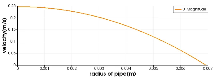
Fig.28 variation of velocity(Y-axis) vs radius of pipe(X-axis) at a particular location
45deg
2.0m from pipe inlet, V_max=0.24764m/s
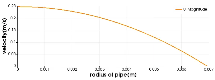
Fig.29 variation of velocity(Y-axis) vs radius of pipe(X-axis) at a particular location
45deg
tau_max=0.063006N/m^2
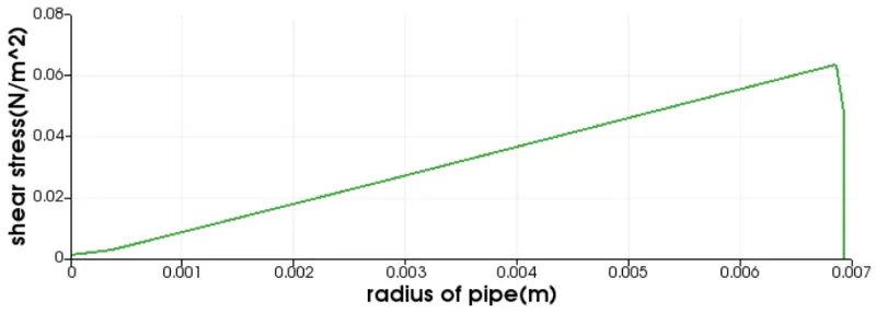
Fig.30
45deg
P_at 1.89m from inlet =0.005654 Pa
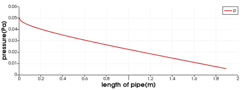
Fig.31
Symmetry boundary condition
matlab code for generating blockMeshDict file
clear all
close all
clc

Re=2100;
D=0.015;
R=D/2;
% R=D/2;
Le=0.06*Re*D;
L=Le+0.3;
rho=997;
mu=0.00089;
nu=mu/rho;
theta=25;
v_avg=(Re*mu)/(rho*D);
v_max=2*v_avg;
delta_p=(32*mu*v_avg*L)/(D^2);
kin_p = delta_p/rho;


file=fopen('blockMeshDict','w')

fprintf(file,'%s\n','/*-------------------------------*- C++ -*-------------------------------------*\')
fprintf(file,'%s\n','===========                 |')
fprintf(file,'%s\n','\\       /    F ield        | OpenFOAM: The Open Source CFD Toolbox')
fprintf(file,'%s\n',' \\     /     O peration    | Website:  http:// openfoam.org  ')
fprintf(file,'%s\n','  \\   /      A nd          | Version   8')
fprintf(file,'%s\n','   \\ /       M anipulation | ')
fprintf(file,'%s\n','\*----------------------------------------------------------------------------*/')

fprintf(file,'FoamFile\n{\n\t')
fprintf(file,'%s\n\t','version   2.0;')
fprintf(file,'%s\n\t','format   ascii;')
fprintf(file,'%s\n\t','class    dictionary;')
fprintf(file,'%s\n','object   blockMeshDict;')
fprintf(file,'}\n\n')
fprintf(file,'%s\n','//* * * * * * * * * * * * * * * * * * * * * *  * * * * * *  * * * * * * //')


fprintf(file,'%s\n','convertToMeters 1;')
fprintf(file,'%s\n','vertices',' (')
fprintf(file,'\t (%d %d %d)\n',0,0,0)
fprintf(file,'\t (%d %d %d)\n',0,R*cosd(theta/2),R*sind(theta/2))
fprintf(file,'\t (%d %d %d)\n',0,R*cosd(theta/2),-R*sind(theta/2))
fprintf(file,'\t (%d %d %d)\n',L,0,0)
fprintf(file,'\t (%d %d %d)\n',L,R*cosd(theta/2),R*sind(theta/2))
fprintf(file,'\t (%d %d %d)\n',L,R*cosd(theta/2),-R*sind(theta/2))
fprintf(file,');\n\n')

fprintf(file,'blocks\n(\n')
fprintf(file,'\t hex (0 3 5 2 0 3 4 1 ) (%d %d %d)',300,20,1)
fprintf(file,' SimpleGrading (1 0.1 1) \n\n);\n\n')

fprintf(file,'edges\n(\n')
fprintf(file,'\t arc %d %d (%d %d %d)\n',1,2,0,R,0)
fprintf(file,'\t arc %d %d (%d %d %d)\n',4,5,L,R,0)
fprintf(file,');\n\n')

fprintf(file,'boundary\n(\n')
fprintf(file,'\t axis\n\t{\n\t\t type empty;\n\t\t faces\n\t\t(\n\t\t (%d %d %d %d)\n',0,3,3,0)
fprintf(file,'\t\t);\n\t}\n')

fprintf(file,'\t wall\n\t{\n\t\t type wall;\n\t\t faces\n\t\t(\n\t\t (%d %d %d %d)\n',2,5,4,1)
fprintf(file,'\t\t);\n\t}\n')

fprintf(file,'\t inlet\n\t{\n\t\t type patch;\n\t\t faces\n\t\t(\n\t\t (%d %d %d %d)\n',0,1,2,0)
fprintf(file,'\t\t);\n\t}\n')

fprintf(file,'\t outlet\n\t{\n\t\t type patch;\n\t\t faces\n\t\t(\n\t\t (%d %d %d %d)\n',3,5,4,3)
fprintf(file,'\t\t);\n\t}\n')

fprintf(file,'\t front\n\t{\n\t\t type symmetry;\n\t\t faces\n\t\t(\n\t\t (%d %d %d %d)\n',0,3,4,1)
fprintf(file,'\t\t);\n\t}\n')

fprintf(file,'\t back\n\t{\n\t\t type symmetry;\n\t\t faces\n\t\t(\n\t\t (%d %d %d %d)\n',3,0,2,5)
fprintf(file,'\t\t);\n\t}\n')

fprintf(file,');\n')
fprintf(file,'mergePatchPairs\n(\n);\n')

fprintf(file,'//******************************************************************************//')
10deg wedge angle with Symmetry boundary condition
blockMeshDict
/*--------------------------------*- C++ -*----------------------------------*\
  =========                 |
  \\      /  F ield         | OpenFOAM: The Open Source CFD Toolbox
   \\    /   O peration     | Website:  https://openfoam.org
    \\  /    A nd           | Version:  8
     \\/     M anipulation  |
\*---------------------------------------------------------------------------*/
FoamFile
{
    version     2.0;
    format      ascii;
    class       dictionary;
    object      blockMeshDict;
}
// * * * * * * * * * * * * * * * * * * * * * * * * * * * * * * * * * * * * * //

convertToMeters 1;

vertices
(
    (0 0 0)
    (0 7.471460e-03 6.536681e-04)
    (0 7.471460e-03 -6.536681e-04)
    (2.190000e+00 0 0)
    (2.190000e+00 7.471460e-03 6.536681e-04)
    (2.190000e+00 7.471460e-03 -6.536681e-04)
);

blocks
(
    hex (0 3 5 2 0 3 4 1) (300 50 1) simpleGrading (1 0.1 1)
);

edges
(
    arc 1 2 (0 7.500000e-03 0)
    arc 4 5 (2.190000e+00 7.500000e-03 0)
);

boundary
(
    axis
    {
        type empty;
        faces
        (
            (0 3 3 0)
        );
    }
    inlet
    {
        type patch;
        faces
        (
            (0 1 2 0)
        );
    }
    outlet
    {
        type patch;
        faces
        (
            (3 5 4 3)
        );
    }
    topWall
    {
        type wall;
        faces
        (
            (1 4 5 2)
        );
    }
    front
    {
        type symmetry;
        faces
        (
            (0 3 4 1)
        );
    }
    back
    {
        type symmetry;
        faces
        (
            (3 0 2 5)
        );
    }
);

mergePatchPairs
(
);

// ************************************************************************* //
25deg wedge angle with Symmetry boundary condition
blockMeshDict
/*--------------------------------*- C++ -*----------------------------------*\
  =========                 |
  \\      /  F ield         | OpenFOAM: The Open Source CFD Toolbox
   \\    /   O peration     | Website:  https://openfoam.org
    \\  /    A nd           | Version:  8
     \\/     M anipulation  |
\*---------------------------------------------------------------------------*/
FoamFile
{
    version     2.0;
    format      ascii;
    class       dictionary;
    object      blockMeshDict;
}
// * * * * * * * * * * * * * * * * * * * * * * * * * * * * * * * * * * * * * //

convertToMeters 1;

vertices
(
    (0 0 0)
    (0 7.322220e-03 1.623297e-03)
    (0 7.322220e-03 -1.623297e-03)
    (2.190000e+00 0 0)
    (2.190000e+00 7.322220e-03 1.623297e-03)
    (2.190000e+00 7.322220e-03 -1.623297e-03)
);

blocks
(
    hex (0 3 5 2 0 3 4 1) (300 50 1) simpleGrading (1 0.1 1)
);

edges
(
    arc 1 2 (0 7.500000e-03 0)
    arc 4 5 (2.190000e+00 7.500000e-03 0)
);

boundary
(
    axis
    {
        type empty;
        faces
        (
            (0 3 3 0)
        );
    }
    inlet
    {
        type patch;
        faces
        (
            (0 1 2 0)
        );
    }
    outlet
    {
        type patch;
        faces
        (
            (3 5 4 3)
        );
    }
    topWall
    {
        type wall;
        faces
        (
            (1 4 5 2)
        );
    }
    front
    {
        type symmetry;
        faces
        (
            (0 3 4 1)
        );
    }
    back
    {
        type symmetry;
        faces
        (
            (3 0 2 5)
        );
    }
);

mergePatchPairs
(
);

// ************************************************************************* //
45deg wedge angle with Symmetry boundary condition
blockMeshDict
/*--------------------------------*- C++ -*----------------------------------*\
  =========                 |
  \\      /  F ield         | OpenFOAM: The Open Source CFD Toolbox
   \\    /   O peration     | Website:  https://openfoam.org
    \\  /    A nd           | Version:  8
     \\/     M anipulation  |
\*---------------------------------------------------------------------------*/
FoamFile
{
    version     2.0;
    format      ascii;
    class       dictionary;
    object      blockMeshDict;
}
// * * * * * * * * * * * * * * * * * * * * * * * * * * * * * * * * * * * * * //

convertToMeters 1;

vertices
(
    (0 0 0)
    (0 6.929096e-03 2.870126e-03)
    (0 6.929096e-03 -2.870126e-03)
    (2.190000e+00 0 0)
    (2.190000e+00 6.929096e-03 2.870126e-03)
    (2.190000e+00 6.929096e-03 -2.870126e-03)
);

blocks
(
    hex (0 3 5 2 0 3 4 1) (300 50 1) simpleGrading (1 0.1 1)
);

edges
(
    arc 1 2 (0 7.500000e-03 0)
    arc 4 5 (2.190000e+00 7.500000e-03 0)
);

boundary
(
    axis
    {
        type empty;
        faces
        (
            (0 3 3 0)
        );
    }
    inlet
    {
        type patch;
        faces
        (
            (0 1 2 0)
        );
    }
    outlet
    {
        type patch;
        faces
        (
            (3 5 4 3)
        );
    }
    topWall
    {
        type wall;
        faces
        (
            (1 4 5 2)
        );
    }
    front
    {
        type symmetry;
        faces
        (
            (0 3 4 1)
        );
    }
    back
    {
        type symmetry;
        faces
        (
            (3 0 2 5)
        );
    }
);

mergePatchPairs
(
);

// ************************************************************************* //
controlDict
/*--------------------------------*- C++ -*----------------------------------*\
  =========                 |
  \\      /  F ield         | OpenFOAM: The Open Source CFD Toolbox
   \\    /   O peration     | Website:  https://openfoam.org
    \\  /    A nd           | Version:  8
     \\/     M anipulation  |
\*---------------------------------------------------------------------------*/
FoamFile
{
    version     2.0;
    format      ascii;
    class       dictionary;
    location    "system";
    object      controlDict;
}
// * * * * * * * * * * * * * * * * * * * * * * * * * * * * * * * * * * * * * //

application     icoFoam;

startFrom       startTime;

startTime       0;

stopAt          endTime;

endTime         18;

deltaT          0.05;

writeControl    timeStep;

writeInterval   20;

purgeWrite      0;

writeFormat     ascii;

writePrecision  10;

writeCompression off;

timeFormat      general;

timePrecision   6;

runTimeModifiable true;


// ************************************************************************* //
pressure
/*--------------------------------*- C++ -*----------------------------------*\
  =========                 |
  \\      /  F ield         | OpenFOAM: The Open Source CFD Toolbox
   \\    /   O peration     | Website:  https://openfoam.org
    \\  /    A nd           | Version:  8
     \\/     M anipulation  |
\*---------------------------------------------------------------------------*/
FoamFile
{
    version     2.0;
    format      ascii;
    class       volScalarField;
    object      p;
}
// * * * * * * * * * * * * * * * * * * * * * * * * * * * * * * * * * * * * * //

dimensions      [0 2 -2 0 0 0 0];

internalField   uniform 0;

boundaryField
{
    inlet
    {
        type            zeroGradient;
    }

    outlet
    {
        type            fixedValue;
        value           uniform 0;
    }
    axis
    {
        type            empty;
    }
    back
    {
        type            symmetry;
    }
    front
    {
        type            symmetry;
    }
    topWall
    {
        type            zeroGradient;
    }
 }

// ************************************************************************* //
velocity
/*--------------------------------*- C++ -*----------------------------------*\
  =========                 |
  \\      /  F ield         | OpenFOAM: The Open Source CFD Toolbox
   \\    /   O peration     | Website:  https://openfoam.org
    \\  /    A nd           | Version:  8
     \\/     M anipulation  |
\*---------------------------------------------------------------------------*/
FoamFile
{
    version     2.0;
    format      ascii;
    class       volVectorField;
    object      U;
}
// * * * * * * * * * * * * * * * * * * * * * * * * * * * * * * * * * * * * * //

dimensions      [0 1 -1 0 0 0 0];

internalField   uniform (0 0 0);

boundaryField
{
    inlet
    {
        type            fixedValue;
        value           uniform (0.124838 0 0);
    }

    outlet
    {
        type            zeroGradient;
    }

    front
    {
        type            symmetry;
    }
    back
    {
        type            symmetry;
    }
    axis
    {
        type            empty;
    }
    topWall
    {
        type            noSlip;
    }


}

// ************************************************************************* //
Results
Plots for symmetry boundary condition
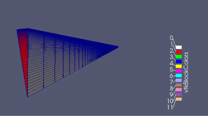
Fig.32 mesh profile for 10deg wedge angle
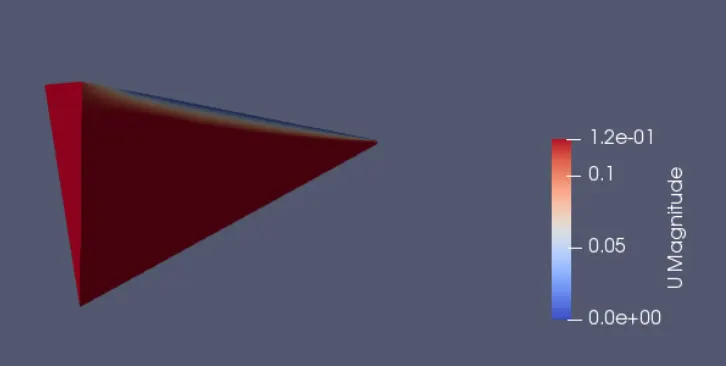
Fig.33 velocity profile for 10deg wedge angle
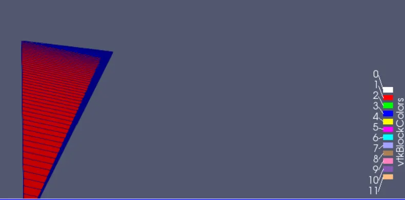
Fig.34 25deg mesh profile
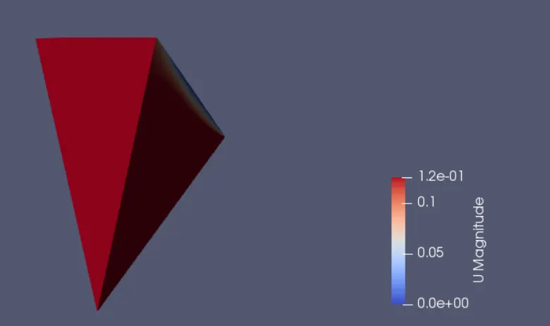
Fig.35 25deg velocity profile
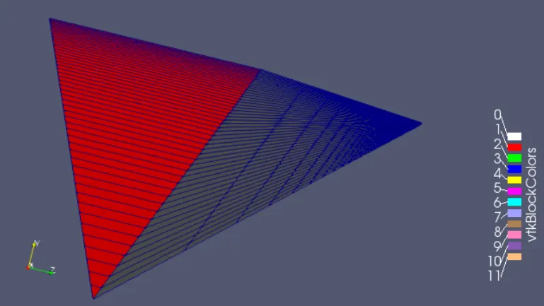
Fig.36 45deg mesh profile
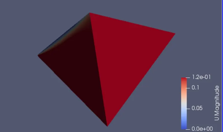
Fig.37 45deg velocity profile
graphs for symmetry boundary condition
10 deg
1.0m from inlet of pipe, V_max=0.237769m/s
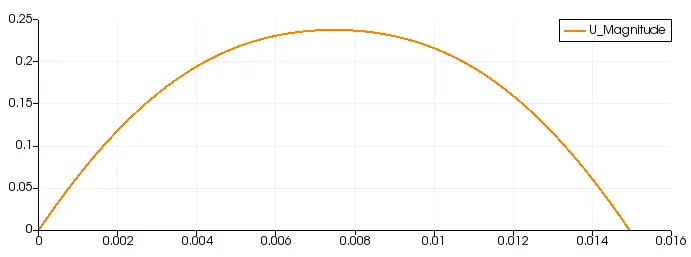
Fig.38. variation of velocity(Y-axis) vs radius of pipe(X-axis) at a particular location
10deg
1.5m from pipe inlet, V_max=0.245212m/s
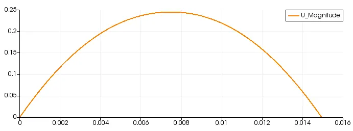
Fig.39 variation of velocity(Y-axis) vs radius of pipe(X-axis) at a particular location
10 deg
1.7m from pipe inlet, V_max= 0.246532m/s
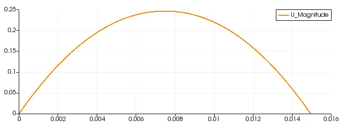
Fig.40 variation of velocity(Y-axis) vs radius of pipe(X-axis) at a particular location
10deg
1.89m from pipe inlet, V_max= 0.247353m/s
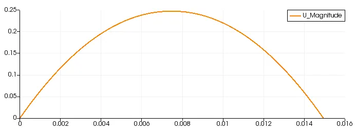
Fig.41 variation of velocity(Y-axis) vs radius of pipe(X-axis) at a particular location
10deg
`tau_max=0.0591375 Pa`
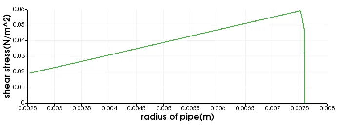
Fig.42 shear stress
10deg
`P_max=0.044679Pa`
P@ 1.89m =0.004945pa
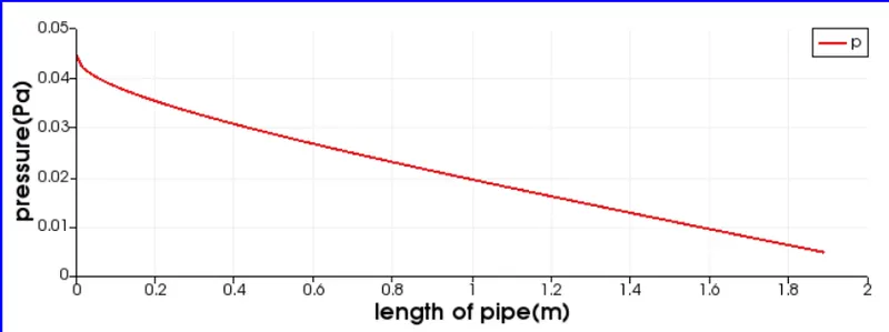
Fig.43
25deg
0.5m from pipe inlet , V_max=0.217068
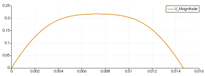
Fig.44 variation of velocity(Y-axis) vs radius of pipe(X-axis) at a particular location
25deg
1.0m from pipe inlet, V_max=0.238718m/s
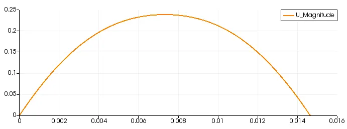
Fig.45 variation of velocity(Y-axis) vs radius of pipe(X-axis) at a particular location
25deg
1.5m from pipe inlet, V_max= 0.245614m/s
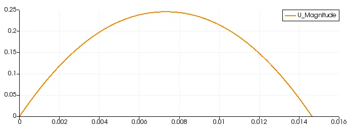
Fig.46 variation of velocity(Y-axis) vs radius of pipe(X-axis) at a particular location
25deg
1.7m from pipe inlet, V_max=0.246819m/s
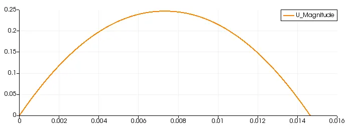
Fig.47 variation of velocity(Y-axis) vs radius of pipe(X-axis) at a particular location
25deg
1.89m from pipe inlet, V_max= 0.247634m/s
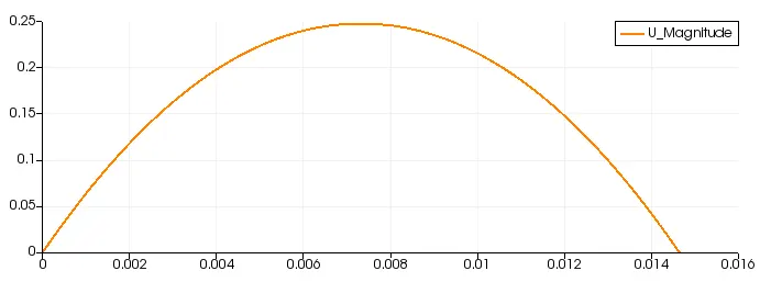
Fig.48 variation of velocity(Y-axis) vs radius of pipe(X-axis) at a particular location
25deg
2.0m from pipe inlet, V_max= 0.247983m/s
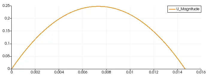
Fig.49 variation of velocity(Y-axis) vs radius of pipe(X-axis) at a particular location
25deg
`tau_max=0.060166 N/m^2`
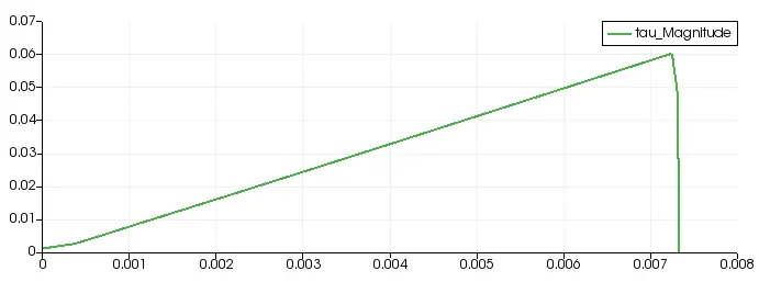
Fig.50 shear stress(Pa) (Y-axis) vs radius of pipe(X-axis) for 25deg wedge angle.
25deg
`P_max=0.046135 Pa`
P_@ 1.89m =0.005237 Pa
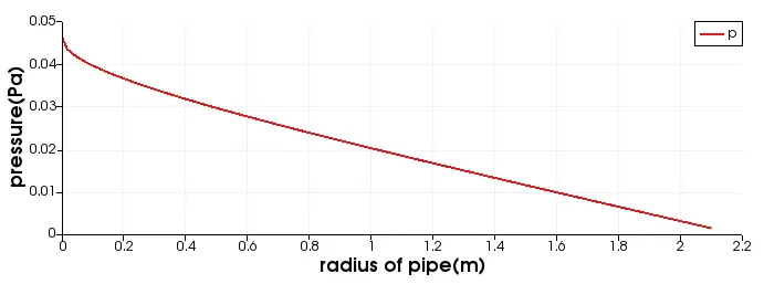
Fig.51 variation of pressure vs pipe length(m)
45 deg
0.5m from pipe inlet, V_max= 0.221062m/s
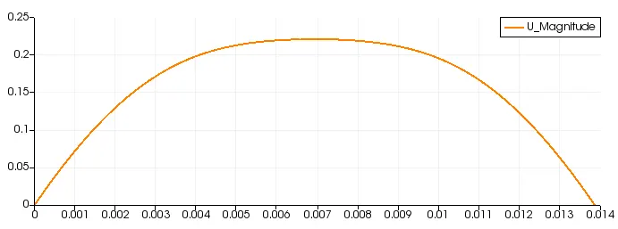
Fig.52 variation of velocity(Y-axis) vs radius of pipe(X-axis) at a particular location
45deg
1.5m from pipe inlet, V_max= 0.246635m/s
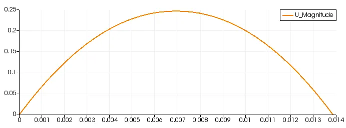
Fig.53 variation of velocity(Y-axis) vs radius of pipe(X-axis) at a particular location
45deg
1.89m from pipe inlet, V_max= 0.248248m/s

Fig.54 variation of velocity(Y-axis) vs radius of pipe(X-axis) at a particular location
45deg
2.0m from pipe inlet, V_max= 0.248456m/s
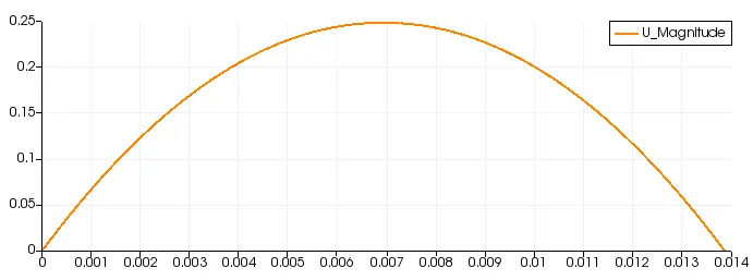
Fig.55 variation of velocity(Y-axis) vs radius of pipe(X-axis) at a particular location
45deg
`tau_max=0.063465 N/m^2`
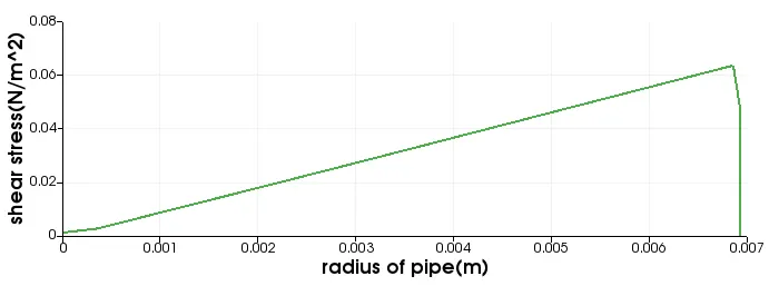
Fig.56
45deg
P_at 1.89m from inlet=0.005564 Pa
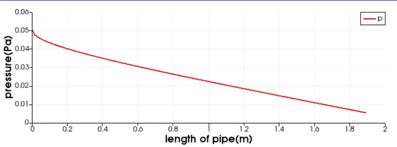
Fig.57
Velocity Validation
Boundary condition V_max(simulation) at 1.89m from inlet V_analytic %error
4deg 10deg 25deg 45deg
wedge 0.247001 0.247031 0.247173 0.247163 0.2499 1.16 , 1.14 ,1.09 ,1.09
symmetry 0.247353 0.247634 0.248248 0.2499 1.01 ,0.90 ,0.66
- Here from the validation table we find that the percentage error for symmetry boundary condition is less than wedge boundary condition and also for a particular wedge angle the symmetry boundary condition gives better result for developed flow.
- As we are seeing the error percentage for velocity for symmetry boundary condition for 10,25 and 45deg wedge angle is less than or equal to 1, so it is giving better simulation result for higher wedge angle.
- If we take a look at the 4deg wedge boundary condition ,the error for velocity is greater than the symmetry boundary condition for all wedge angle and also the error is very small to consider.
shear stress validation
Boundary condition tau_max(simulation) at 1.89m from inlet tau_analytic %error
4deg 10deg 25deg 45deg
wedge 0.0598432 0.063006 0.063396 0.063006 0.059500 0.5, 5.8, 6.5, 5.8
symmetry 0.059137 0.060166 0.063465 0.059500 0.61, 1.11, 6.6
- From the data shown above ,it is found that the shear stress for wedge boundary condition is remaining approx constant value if we increase the wedge angle or sector angle .
- For symmetry boundary condition, the error is increasing as we increase the wedge angle but it is lower than 10%. As the error value is very small for lower wedge angle as compared to wedge boundary condition, it is giving better simulation result.
Pressure -drop Validation
Boundary condition press_drop(simulation) at 1.89m from inlet press_analytic
10deg 25deg 45deg
wedge 0.0446 0.0448 0.0447 0.0347
symmetry 0.0397 0.0408 0.0483 0.0347
- Pressure drop values are showing nearly constant values for all wedge angle for wedge boundary condition.Here the outlet is taken as the entrance length,i.e upto the entrance region (1.89m from inlet) ,the pressure drop values are shown for repective wedge angle.
- For symmetry boundary condition, the pressure drop is maximum for lower wedge angle i.e, for 10deg and 25deg , the pressure drop is maximum as compared to 45deg wedge angle.
use of symmetry and wedge boundary condition
- symmetry boundary condition is used for 3D objects under consideration, whereas the wedge boundary condition for axis- symmetric and 2D objects.
- symmetry is used in order to reduce the computation time and also the number of cell and complexity.
- The conditions for symmetric boundary are no flow across boundary , no scalar flux across boundary.
Conclusion
- The clock time for symmetry boundary condition is somewhat greater than wedge boundary condition.
- The percentage error for velocity in symmetry boundary condition is lesser than the wedge boundary condition.
- For shear stress, the symmetry boundary condition shows better result for wedge angle upto 30deg, as the error for shear stress values for 45deg is greater than all other wedge angle. Overall the error values are less than 10 percentage.
This concludes the objective of this project work.