Week 12:Project 2-Meshing of Rear Wheel Holder challenge
AIM:
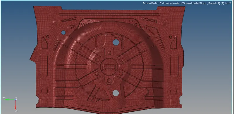
To create a 2D mesh in the Rear-wheel holder component according to the quality criteria, and apply thickness to the mesh.
QUALITY CRITERIA:
| S.N | Quality Criteria | Value |
| 1 | Aspect Ratio | 5 |
| 2 | Skewness | 45 |
| 3 | Warping | 15 |
| 4 | Taper | 0.5 |
| 5 | Min. Length | 2mm |
| 6 | Max. Length | 8mm |
| 7 | Min angle Quad | 45 |
| 8 | Max angle Quad | 135 |
| 9 | Min angle Tria | 20 |
| 10 | Max angle Tria | 120 |
| 10 | Tria % | 10 |
PROCEDURE:
Import the model in hypermesh
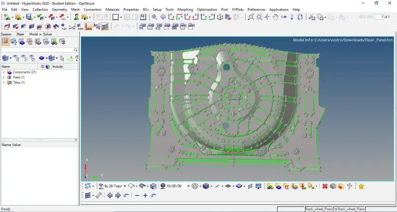
after importing the model, there will be topology errors in the component. topology is that how surfaces connect to adjacent surfaces of a part. lines are in different colors for representations of the surface.
free edge (red color)- associated with only 1 surface
- surface with a free edge between them are not equivalent at that edge.
shared edge(green color)- surfaces are equivalent and associate with two surfaces.
T- junction edge ( yellow color) - associate with 3 or more surfaces
- surface forming a T-connection
- surfaces are equivalent
suppressed edge ( blue color)- surfaces are treated as tough combined into one surface.
Topology repair consisting of correcting connectivity errors between adjacent surfaces. they are unconnected adjacent surfaces, duplicate surfaces, missing surfaces.
MIDSURFACE EXTRACTION:
We have to take mid surface for the component so that we can do meshing on the component. for that go to geom -> mid surface -> select the component -> extract.
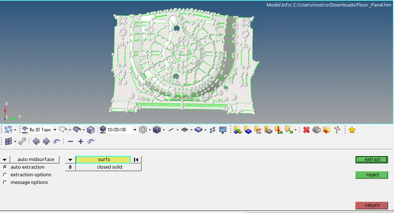
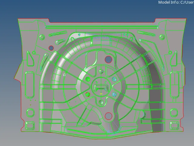
MIDSURFACE
DEFEATURING:
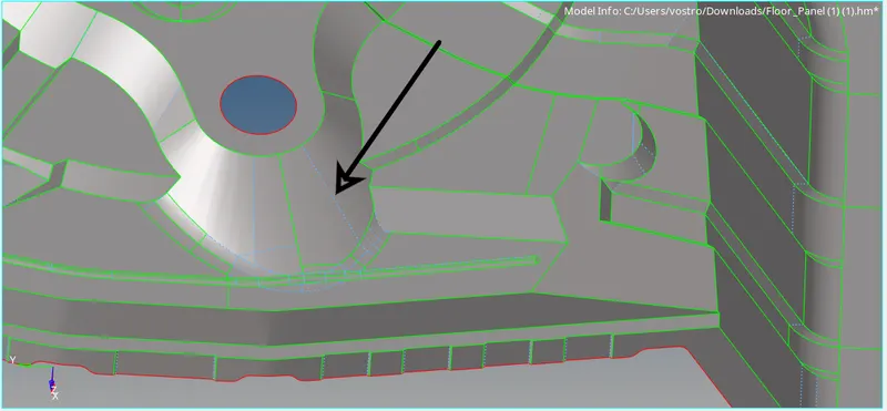
Defeaturing means removing unnecessary construction lines and curves in the CAD model because of manufacturing constraints. we have to remove them or arrange them properly for a better mesh flow without failing quality criteria. Very small entities can be a problem if you have a very small face with sharp angles, meshing might get fail. Therefore check the CAD model for very small entities and remove them before creating a mesh for it.
QUALITY CRITERIA SETUP:
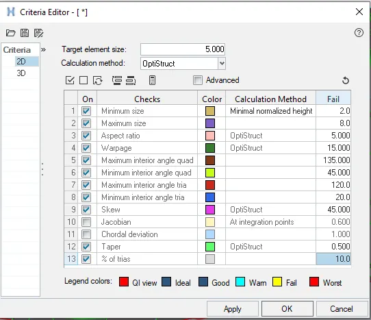
We must assign quality parameters such that meshing elements will get measured from their ideal shape. The parameters like warping, skewness, aspect ratio, etc.. have to be given in the quality criteria setup. meshing parameters also have to give before meshing such that surface will get mesh under given length
MESHING:
Meshing is an integral part of the engineering simulation process where complex geometries are divided into simple elements that can be used as discrete local approximations of the larger domain. It is a network that is formed of cells and points.
Now we can finally mesh the component after defeaturing the complex areas. there must be better mesh flow in the component. we can start meshing the midsurface. there we can use the auto mesh option in 2d panel to mesh the surface.
Go to 2D PANEL> AUTOMESH>Select the surfaces needed to mesh>give the element size as 4 mm > MESH
Then the whole surface got meshed. with the radio button in density, we can clean change the nodal densities at various locations so as to get a smooth mesh with a lower number of trias. Before accepting the mesh we should change the densities in such a way that the maximum tria removal is possible. Then accept the mesh. Various things to keep in mind in meshing
- If there are any opposite trias, we should re-mesh these trias, and thereby we can remove those trias.
- There should not be any mesh transition at the fillet regions.
- The smoothing command can be used to smoothen the mesh. For that go to TOOL panel >click on SMOOTH> Select the elements needed to smooth>Click on smooth until we get even mesh flow.
- Never place TRIA elements at the edges or inside the washer.
- Adjacent TRIAS must be removed. For that we can use DRAG TRIA option in QUALITY INDEX tab in 2D panel. We can select the tria and drag it to any other position so that we can remove the adjacent trias.
- Rotating Quads are not acceptable in CRASH TEST but acceptable in structural analysis. Same directional following TRIA elements are acceptable in CRASH ANALYSIS but not permissible in structural analysis.
- Always mesh the component keeping in mind the quality requirements.
For fixing quality issues we use the quality index in 2D panel

- Place node option is used to move the nodes freely to minimize the quality
- the smooth option is used to smooth the mesh flow
- Element optimize is used to optimize the element quality
- Drag tria is used to drag the tria elements from one side to another
- The split quad element option is used to split quad elements into two tria elements.
- Combine tria elements is that combining two tria into one quad element.

a smooth option is used to smooth the mesh flow when it is distorted.

The rebuild option gives better mesh flow but sometimes we will be facing connectivity issues.
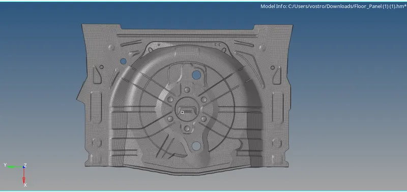
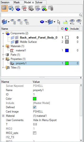
Meshing has been done on the component, after that, we want to assign thickness for the component. To assign thickness we need to create a property for the component.
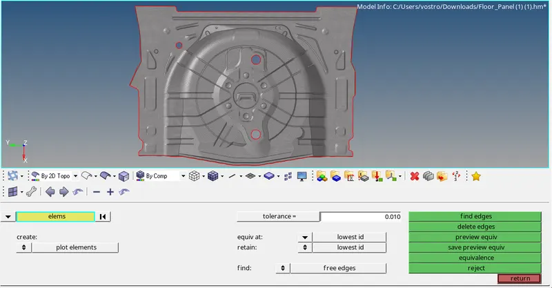
we want to check for free edges in the model, from that we able to know the element connectivity issues. For that go to TOOLS -> EDGES or SHIFT +F3. from the below image we came to know that there are no free edges present in the model.
RESULT:
AFTER MESHING
CONCLUSION:
The given Rear-wheel holder panel has a consistent thickness, the mid surface was easily taken using an auto-mid surface option. But the model contains several sharp edges which were a major concern during the meshing process. warpage was the major issue which I faced in the sharp edges. So I eliminated them by using the translate option. This model was a very complex model to capture features in detail.