Side crash analysis simulation using hypermesh/ Radioss
AIM: Side crash analysis simulation using hypermesh/ Radioss on the car BIW structure.
OBJECTIVE:
- Check unit system and either follow [Mg mm s] or [Kg mm ms].
- Create an appropriate interface, friction 0.2, and recommended parameters.
- Make sure of no penetration and intersections.
- Create a rigid wall with friction 0.1 as per the reference model.
- Compare the model weight with the reference model and use added masses to reach the target weight of 700kg while getting CG about the required range.
- Initial velocity as shown in the picture.
- Use a model checker to ensure good quality.
- Timestep :0.5 to 0.1 microseconds.
- Run 80ms.
CRASHWORTHINESS:
Crashworthiness is the ability of a structure to protect its occupants during an impact. It is used when investigating the safety of vehicles. Depending on the nature of the impact, different criteria are used to determine the crashworthiness of the structure. Crashworthiness may be assessed either using computer models or experiments by analyzing crash outcomes. Several criteria are used to assess crashworthiness prospectively, including the deformation patterns of the vehicle structure, the acceleration experienced by the vehicle during an impact, and the probability of injury predicted by human body models. Injury probability is defined using criteria, which are mechanical parameters (e.g., force, acceleration, or deformation) that correlate with injury risk. Crashworthiness research encompasses new and improved vehicle design, safety countermeasures, and equipment to enhance occupant safety
SIDE CRASH ANALYSIS:
Some side impacts involve a vehicle traveling sideways into rigid roadside objects such as trees or poles. Often this is the result of a loss of control on the part of the driver, owing to speeding, misjudgment of a corner, or because of a skid in slippery conditions. Such accidents are severe and the frequency of death or serious injury is high. In Euro NCAP’s test, a car is propelled sideways at 32 km/h against a rigid, narrow pole. The car is placed at right angles to the direction of motion at a small angle away from the perpendicular.
This is a very severe test of a car’s ability to protect the driver’s head. As the loading on the car is so localized, deformation can be very high and the pole can penetrate deeply into the passenger compartment. Without effective protection, the pole would strike the head resulting in serious injuries. Head protection airbags – often curtain airbags mounted above the side windows but sometimes seat-mounted thorax/head airbags – have become a common solution but great care is needed to ensure effective performance of such devices.
METHODOLOGY:
- Import the model in hypercrash / Radioss (hypermesh)
- check for unit system
- setup boundary conditions, interfaces, and recommended properties
- setup output requests for required results.
- Run the model checker to check for errors and warnings.
- Run the simulation to get output in the form of animation or graphs.
UNIT SYSTEM:
We have to maintain the same unit system throughout the model because it leads to the wrong result after the simulation. we have to check the starter file before importing the model to hypermesh, so we came to know which unit system is applied on the model and we can change recommended units in the starter file. when I checked the starter file the units were kg mm ms

MODEL:
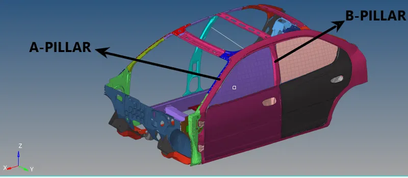
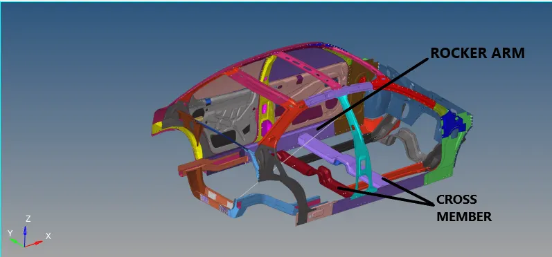
COG/ MASS ADDITION:
Mass addition is an essential factor that we need to assign before running the simulation. we have to keep the COG point in the middle of the model to attain good results. The center of gravity of any vehicle is the point that sums up the vehicle's mass in one central point.
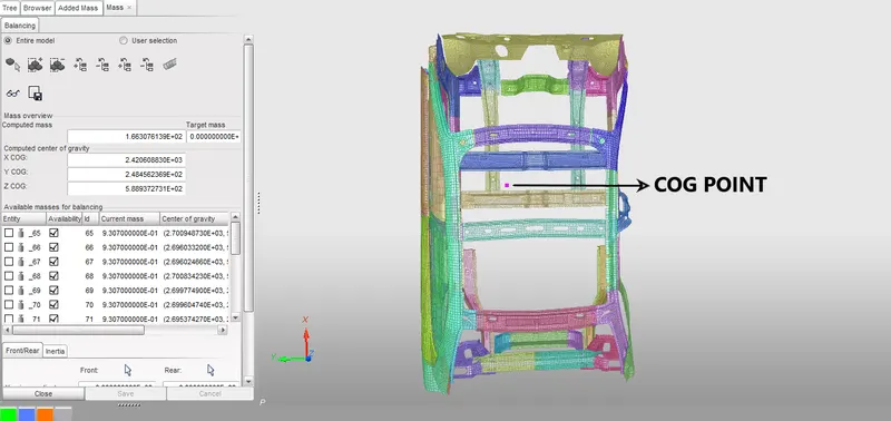
When making an analysis of the forces applied to the car, the COG is the point to place the car weight, and the centrifugal forces when the car is turning or when accelerating or decelerating. Any force that acts through the COG has no tendency to make the car rotate. The total mass is 166 kg which is very less to run the simulation, and the COG point is at the dashboard. this is the actual mass present in the given model.
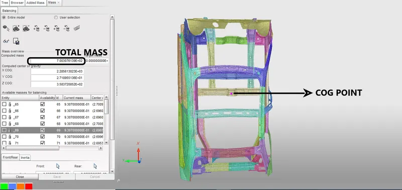
we have to attain 700kg and the COG point in the cross member. so we have to add mass in the vehicle to get COG point in the cross member. the mass can be added in the hypercrash so that we can see the COG point clearly. In hypercrash go to Loadcase -> added mass to add mass in the vehicle. create a mass with type 1 so that mass will equally be distributed to selected nodes. give the required amount of mass and select the area to be applied.
CONTACT INTERFACE:
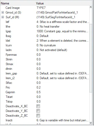
We have to create a contact in the BIW model. so that elements and nodes will get in contact with each other during the simulation. It is a required step to create an interface between them. I have decided to create a TYPE 7 contact with the recommended parameters. because type 7 is a node to surface contact. In hypermesh go to BCs -> create -> interface to create a contact interface. select the entire model for master and slave nodes to be a self contact.
INITIAL VELOCITY:
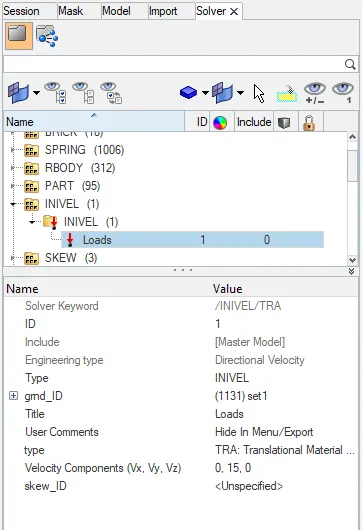
We have to mention initial velocity to the BIW car structure so that it moves given velocity and crashes to a rigid wall. I have given translational velocity with respect to X-axis. The given velocity is 35 mph which is converted into 15 mm/ms. for creating initial velocity go to solver-> create -> boundary conditions -> INIVEL .
RIGID WALL SETUP:
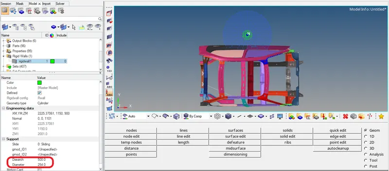
Rigid wall setup is an important step to be carried out. it allows the creating of an interface between rigid nodes and nodes of a deformable body. the rigid wall is part that will be lead to a crash of a present geometry. I have created an infinite plane rigid wall in front of the car so that the car model will get crash from the front side. I have given search distance as 1216mm from the rigid wall so that nodes present in the car will act as slave nodes and helps to crash as a real scenario against a wall. For setup go to BCs -> create -> rigid wall
SECTION CREATION FOR SECTION FORCE CALCULATION:
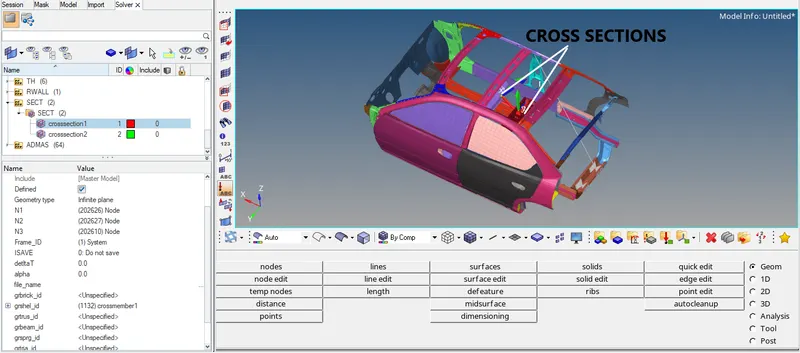
We have to create a section for calculating sectional force in the particular components. we have to select components and then we have to create a frame for local coordinates and then select a respective frame for a component. create a set for a group of elements present in the component for defining the shell id.For creating a section go to SOLVER -> CREATE -> SECT.
INTRUSION POINT :
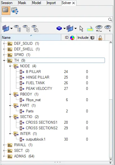
We need to set up some intrusions points so that we will get an idea about the displacement of nodes in the impact area. we are selecting three points from the impact zone. B-pillar, hinge pillar, fuel tank are the region where the place we need to check the displacement. we need to set up the time history file so that we can extract the results after simulation.
TIME-STEP :
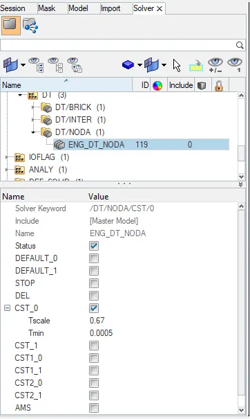
The time needed for information to cross the smallest distance in an element. the computed time step is compared to a minimum time step value and a scale factor is applied to ensure a conservative bond. the time step can be controlled by three types CST, DEL, STOP. we use CST type because elements are switched to small strain formulation to maintain the constant time step. it will add some mass to the nodes to increase density. so that speed of the sound waves varies. the nodal time step is calculated after the computation of all internal forces at each node. for creating time step solver -> engine keywords ->DT -> DT/NODA. we have time step as 0.0005 ms and scale factor as 0.67.
OUTPUT REQUEST:
We have to create some output requests to check the forces act on the sections and few areas where intrusions and accelerometers are setups. To create an output request go to solver browser -> create -> TH -> INTER / NODE / SECTIO / ACCEL. output blocks are created for sections, intrusions, accelerometers, contact interface.
PENETRATION CHECK / MODEL CHECKER:
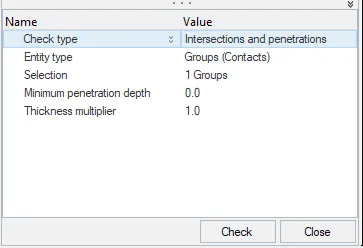
After defining the contact interface between nodes and elements, we have to check for initial penetrations and remove them before simulation. For penetration, check go to TOOLS -> PENETRATION CHECK. select the group in which we want to check the initial penetration. I have selected 2 interfaces to check and there is no initial penetration present on the model.
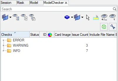
The model has to be checked before running the simulation. there will be errors and warnings after checking the model. errors need to be cleared and warnings can be ignored and some important warnings need to be cleared because they will lead to minor errors.
ENGINE OUTPUT FILE:
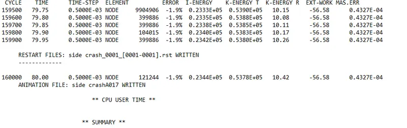
Energy error is -1.9% which is acceptable as per standard. the energy error is negative which indicates energy has been dissipated. mass error is 0.4327E-04, to compensate for the mass which is added to nodes and registered as a mass error. as per standard mass error till 1% is acceptable. our simulation is stable as per results. the total simulation time is 1hr 57min 13sec.
RESULT:
VON-MISSES STRESS ANIMATION:
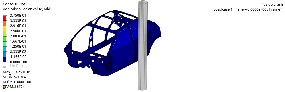
The maximum stress is 3.75E-01 at node 521914. from the above animation, BIW structure achieves bad deformation, but in a real scenario, it won't be like this deformation. since there are components missing in the model, force is distributed to only BIW structure, so that it deforms badly.
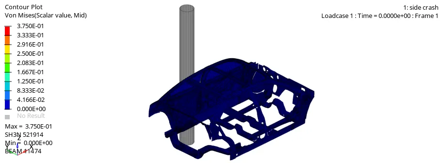
B-pillar on the left side receives maximum force since it impacts first, the deformation is more on the left side, components which are near to B-pillar receives maximum stress and deforms badly. It is only BIW structure crash, when it compares with a real-life crash the deformation will be different.
DISPLACEMENT ANIMATION:
ENERGY PLOT:
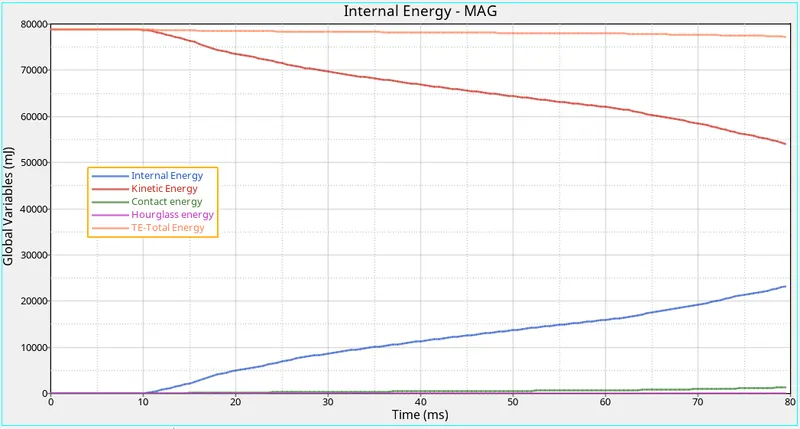
From the energy plot, kinetic energy reduces gradually after getting impact on the pole. internal energy increases when deformation starts after the impact. because kinetic energy is converted into internal energy after the impact. Hourglass energy is maintained at zero since we are using QEPH element formulation. the contact energy has been increased further because during deformation their components get contact with each other.
INTRUSIONS POINTS:
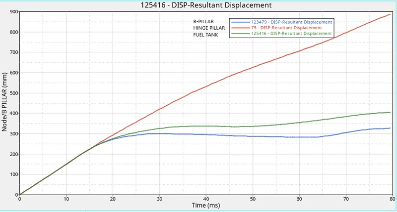
From the above graph, the maximum displacement is at the hinge pillar, because B-pillar gets impacts on the pole and deforms near the pole, but the hinge pillar receives force and deforms badly by huge displacement. fuel tank receives less force and deforms less than B-pillar. we need to add stability to the hinge pillar by changing material properties. because passengers will get hurt when the hinge pillar deforms badly like this in a real scenario.
SECTION FORCES:
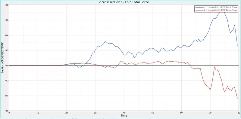
Section force is used to find out force travels in a particular component. crossmember A receives the maximum force after impact and they deform badly. cross member B experiencing less force compare to cross-member A. If we see in the simulation cross member A is near to B-pillar, since the impact is in B-pillar, the force travels cross-member will be large. we have to improve the stability of the cross member to avoid a collision in the passenger compartment.
PEAK VELOCITY FOR INNER NODE OF THE DOOR
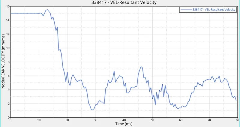
From the above graph, it shows that how much displacement happens on the inner side of the door during impact. The peak velocity measured on the inner side of the door is 15.52mm/ms2 at 13 ms. After impact velocity has reduced gradually till the end of the simulation.
CONCLUSION:
As a result, the simulation is stable after checking the engine output file. Cross-member absorbs maximum energy, so we have to improve cross member by adding some stiffness and changing the material properties. B-pillar also needs to improve since it's played a major role in side pole crash. By improving their properties we can avoid impact to passengers during side crashes.