Roof Crashworthiness Analysis of a car using Hypermesh and RADIOSS
AIM: Roof crash analysis using Radioss and hypercrash
OBJECTIVE:
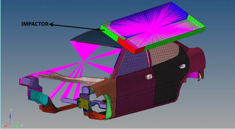
- Arrange the position of the impactor and simulate a roof crash with suitable interfaces.
- create impactor boundary conditions to guide the master node of the impactor rigid body so that it is free to translate normally to the face of the impactor, but is fixed in all other DOFs.
- Impose the velocity of the impactor starting from 0 mm/s at t = 0. The displacement of the impactor should be 200 mm @ 200 ms.
- create an engine file to Use a constant nodal time step and Print time history every 0.0001 seconds
- Plot force vs. displacement. Check that the FMVSS 216 target load of 47,000 N (= 3 * GVW) has been met
- Plot the energy vs. time curve.
CRASHWORTHINESS:
Crashworthiness is the ability of a structure to protect its occupants during an impact. It is used when investigating the safety of vehicles. Depending on the nature of the impact, different criteria are used to determine the crashworthiness of the structure. Crashworthiness may be assessed either using computer models or experiments by analyzing crash outcomes. Several criteria are used to assess crashworthiness prospectively, including the deformation patterns of the vehicle structure, the acceleration experienced by the vehicle during an impact, and the probability of injury predicted by human body models. Injury probability is defined using criteria, which are mechanical parameters (e.g., force, acceleration, or deformation) that correlate with injury risk. Crashworthiness research encompasses new and improved vehicle design, safety countermeasures, and equipment to enhance occupant safety.
ROOF CRASH ANALYSIS:
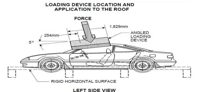
The passengers experience major injuries like the neck, head, and spine injuries. So, to reduce the injuries of a passenger from major fatalities it is important to provide safety in the car. Though safety is provided by seat belts and airbags during accidents, the passenger must have sufficient space for survival in the car during accidents. The roof of the car must have a high strength to resist the crash force to avail the passenger some space for survival. Therefore, in this project, we have carried out a roof crush test using the Federal Motor Vehicle Safety Standards (FMVSS216) standards in hypermesh.
FMVSS 216 ROOF CRASH STANDARDS
FMVSS 216, Roof Crush Resistance, establishes strength requirements for the passenger compartment roof of passenger cars, multipurpose passenger vehicles, trucks, and buses with a GVWR of 2722 kilograms or less. The purpose of the standard is to reduce deaths and injuries due to the crushing of the roof into the passenger compartment in rollover accidents. The standard does not apply to school buses and passenger cars that conform to the dynamic rollover test requirements of FMVSS 208, Occupant Crash Protection, and S5.3 by means that require no action by passenger car occupants. It also does not apply to convertibles, except for optional compliance with the standard as an alternative to the rollover test requirements in S5.3 of FMVSS. The force shall be applied in a downward direction perpendicular to the lower surface of the static loading device at a rate of not more than 13 millimeters per second until reaching the compliant resistive load. The test shall be completed within 120 seconds.
METHODOLOGY:
- Import the model in hypercrash / Radioss (hypermesh)
- check for unit system
- setup boundary conditions, interfaces, and recommended properties
- setup output requests for required results.
- Run the model checker to check for errors and warnings.
- Run the simulation to get output in the form of animation or graphs.
UNIT SYSTEM:
We have to maintain the same unit system throughout the model because it leads to the wrong result after the simulation. we have to check the starter file before importing the model to hypermesh, so we came to know which unit system is applied on the model and we can change recommended units in the starter file. when I checked the starter file the units were kg mm ms

MODEL:
CONTACT INTERFACE:
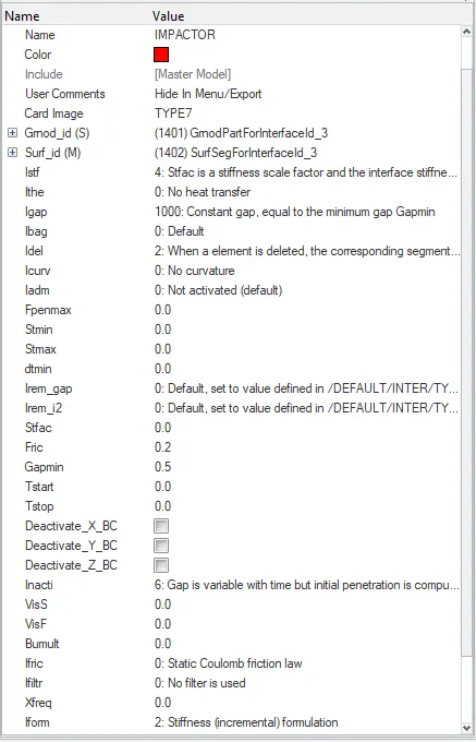
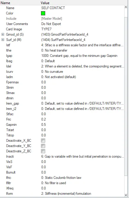
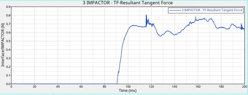
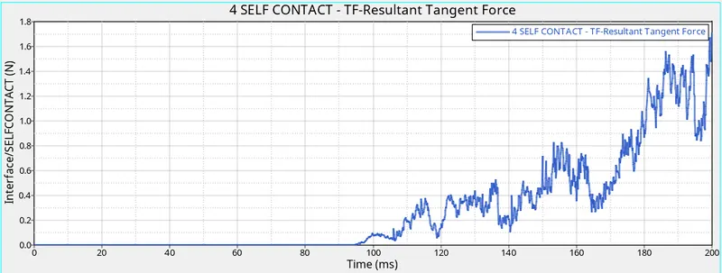
We have to create a contact in the BIW model. so that elements and nodes will get in contact with each other during the simulation. It is a required step to create an interface between them. I have decided to create a TYPE 7 contact with the recommended parameters. because type 7 is a node to surface contact. In hypermesh go to BCs -> create -> interface to create a contact interface. select the entire model for master and slave nodes to be a self contact. we have to create two contacts, one is for self contact as the car gets crushed and the other is for contact interface between the impactor and the car. we are creating TYPE 7 contact for two contacts. For self impact, the slave node and the master node will be a car model and for the second case the slave node will be a car, and the master node will be the impactor.
BOUNDARY CONDITIONS:
We need to create boundary conditions for the model wherever it's needed. The impactor assembly contains a spring attached for stability. we have to create a BCS collector to fix the free end of the spring. after creating BCS select the master node and select all boxes to constrain a node. In the next condition create a BCS collector to guide the master node of the impactor rigid body so that it is free to translate normally to the face of the impactor, but is fixed in all other DOFs. Create a moving SKEW to define the direction normal to the impactor face. select the master node of the impactor and select the skew id where we created SKEW MOV and constrain all directions except translational Z direction.
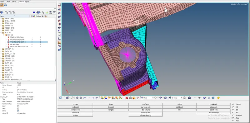
we have to keep suspension shock tower nodes locked in Z, for that we have to create a rigid connection with the 1D browser. select all the nodes in the circle which will act as slave nodes and the master node is obtained by the algorithm. create a BCS select the master node and then lock translational Z which is DOF 3. This is step is repeated for another suspension shock tower.
IMPOSED DISPLACEMENT:
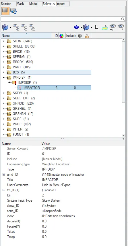
We have to create imposed displacement so that the impactor has to maintain that Displacement throughout the simulation. If there is any obstruction, still the object continues to move with the defined displacement. we have to create a skew so that we can define it in the skew id. The impactor will move with respect to skew id. Mention a direction as Z so that impactor will move in that direction. It needs a function curve for data and we are defining a curve with two entries by time and displacement.
TIME-STEP :
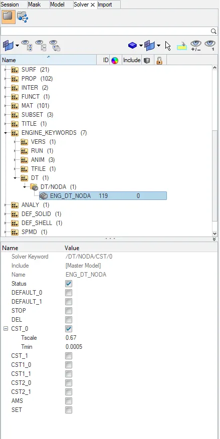
The time needed for information to cross the smallest distance in an element. the computed time step is compared to a minimum time step value and a scale factor is applied to ensure a conservative bond. the time step can be controlled by three types CST, DEL, STOP. we use CST type because elements are switched to small strain formulation to maintain the constant time step. it will add some mass to the nodes to increase density. so that speed of the sound waves varies. the nodal time step is calculated after the computation of all internal forces at each node. for creating time step solver -> engine keywords ->DT -> DT/NODA. we have time step as 0.0005 ms and scale factor as 0.67. Print time history every 0.0001 seconds and create an animation file every 0.005 seconds.
PENETRATION CHECK / MODEL CHECKER / CONNECTIVITY CHECK :
After defining the contact interface between nodes and elements, we have to check for initial penetrations and remove them before simulation. For penetration, check go to TOOLS -> PENETRATION CHECK. select the group in which we want to check the initial penetration. I have selected 2 interfaces to check and there is no initial penetration present on the model.
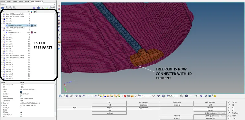
The model has to be checked before running the simulation. there will be errors and warnings after checking the model. errors need to be cleared and warnings can be ignored and some important warnings need to be cleared because they will lead to minor errors. we have to check connectivity to see free parts are present in the model. I have checked connectivity from TOOLS -> FIND CONNECTIVITY. There are many free parts are present in the model. so I have connected them with 1d element.
ENGINE OUTPUT FILE:
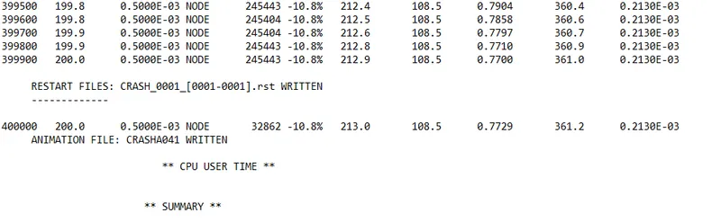
Energy error is -10.8% which is acceptable as per standard. the energy error is negative which indicates energy has been dissipated. mass error is 0.2130E-03, to compensate for the mass which is added to nodes and registered as a mass error. as per standard mass error till 1% is acceptable. our simulation is stable as per results. the total simulation time is 5hr 16min 31sec.
RESULT:
VON MISSES STRESS ANIMATION:
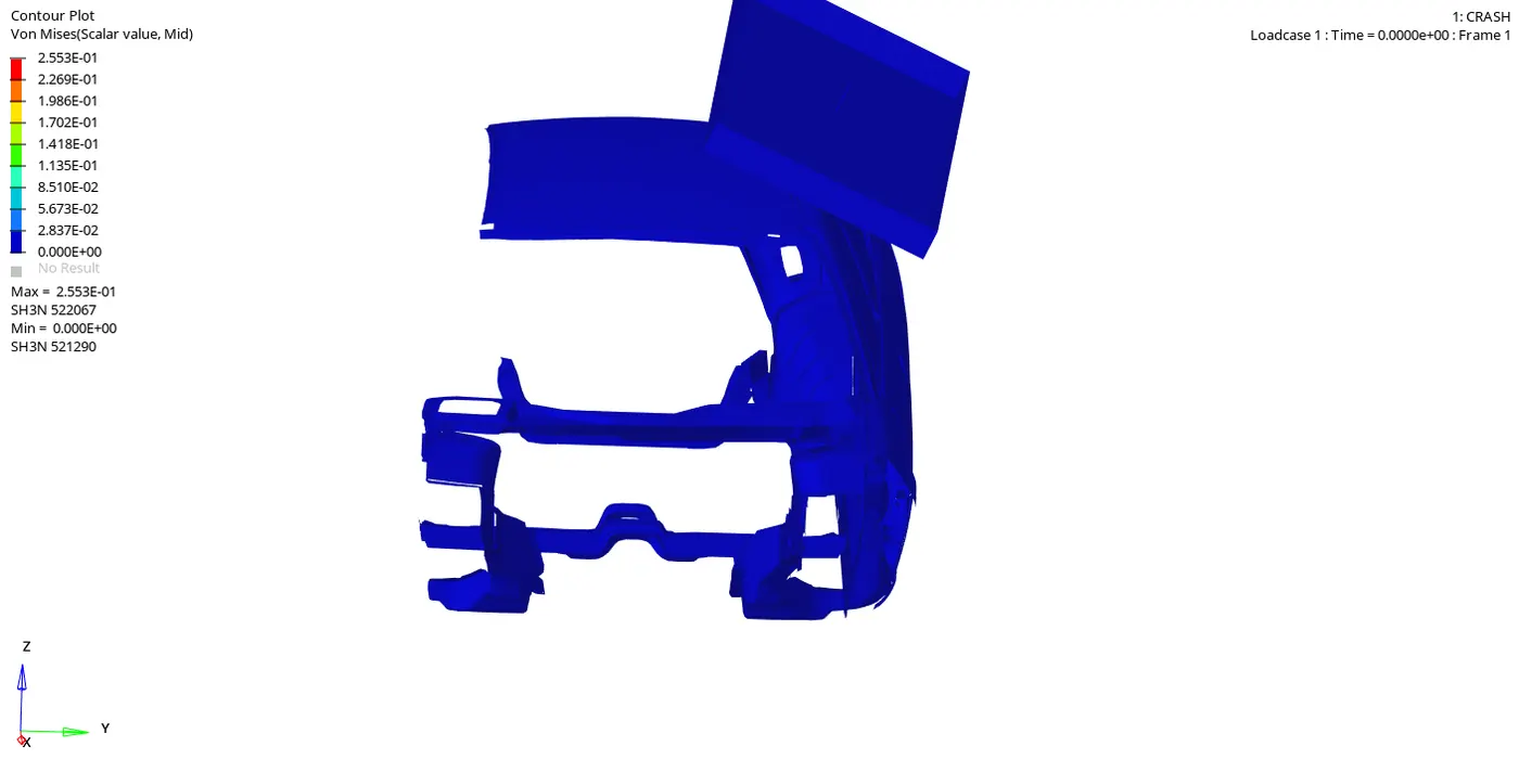
The maximum stress is 2.553E-01 at node 522067. we can observe that stress is widely spreading from roof to frontal structure. Two cross members, A-pillar, and B-pillar areas also affected and deformed. some parts are thrown away during a simulation because they are not connected or connected with one side with 1D elements. Hypermesh won't show as free part because they are connected with one side. since it's only a BIW structure, stress propagation is only through a structure. If we have a full car model, we can analyze the stress distribution in the interior, so that it easy to know whether passengers experiencing major injuries in the neck, head, and spine injuries.
DISPLACEMENT ANIMATION:
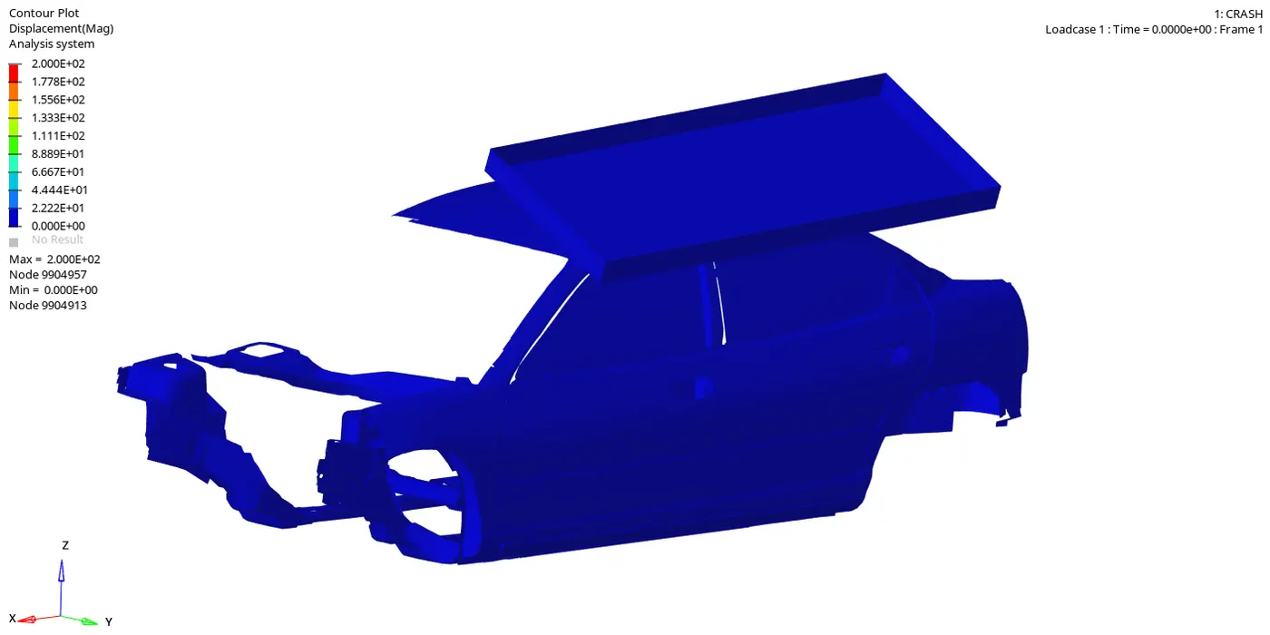
ENERGY PLOT:
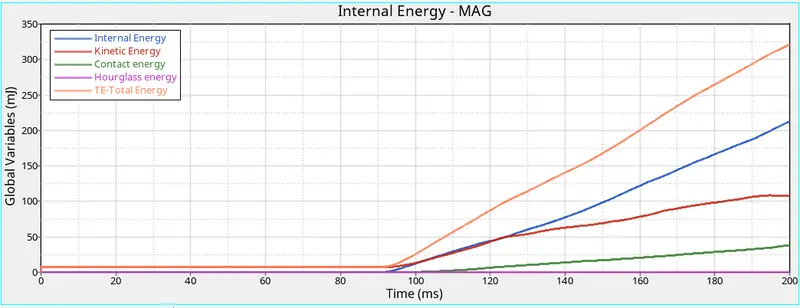
Kinetic energy is low than internal energy because it is a quasi-static simulation. hourglass energy is very less because we have used the QEPH shell element formulation. Internal energy is increasing after an impact. contact energy is increasing after 110ms because once the stress is propagated, the deformation happens and elements get in contact with each other. the total energy is a summation of internal, kinetic, contact, and hourglass energy.
INTERFACE OF IMPACTOR AND CAR BODY
SELF CONTACT INTERFACE:
FORCE VS DISPLACEMENT
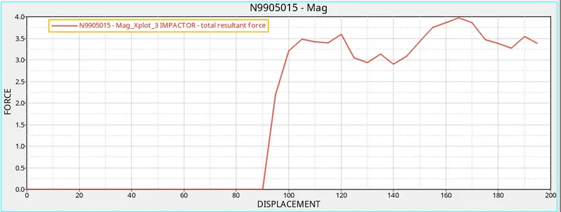
We are going to check maximum force experienced on the impactor is equal to three times to gross vehicle weight(GVW).as this not a full model but we can make calculations by using the mass of the car.
FORCE= 175*9.81*3 = 5.15KN.
The maximum value of force obtained from the graph is 4KN, which is not close to 5.15KN.
CONCLUSION:
As a result, we need to improve in the area of A-pillar, doors, side members by changing material and improving stiffness on them. so that they can withstand the load which is acting on it and prevent the passenger compartment. we have followed the FMVSS 216 roof crush method for our analysis. we have used a model checker and found errors and warnings and they cleared.