Frontal car BIW structure crash analysis using hypermesh/ radioss.
AIM:
Frontal car BIW structure crash analysis using hypermesh/ radioss.
OBJECTIVE:
- Check the unit system and either follow[Mg mm s] or [Kg mm ms].
- Create an appropriate interface, friction 0.2, and recommended parameters.
- Make sure of no penetrations and intersections.
- Correct rigid bodies if any issues.
- Create a rigid wall with friction 0.1.
- Compare the model weight with the full-scale 300k nodes model and use added masses to reach the target weight of 700kg while getting COG about the required range.
- Initial velocity 35 mph.
- Use a model checker to ensure good quality.
- Time-step :0.5 to 0.1 microseconds.
- Run 80 ms.
CRASHWORTHINESS:
Crashworthiness is the ability of a structure to protect its occupants during an impact. It is used when investigating the safety of vehicles. Depending on the nature of the impact, different criteria are used to determine the crashworthiness of the structure. Crashworthiness may be assessed either using computer models or experiments by analyzing crash outcomes. Several criteria are used to assess crashworthiness prospectively, including the deformation patterns of the vehicle structure, the acceleration experienced by the vehicle during an impact, and the probability of injury predicted by human body models. Injury probability is defined using criteria, which are mechanical parameters (e.g., force, acceleration, or deformation) that correlate with injury risk. Crashworthiness research encompasses new and improved vehicle design, safety countermeasures, and equipment to enhance occupant safety.
METHODOLOGY:
- Import the model in hypercrash / Radioss (hypermesh)
- check for unit system
- setup boundary conditions, interfaces, and recommended properties
- setup output requests for required results.
- Run the model checker to check for errors and warnings.
- Simulate to get output in the form of animation or graphs.
FRONTAL CRASH TEST:
A frontal crash is the most common crash resulting in a fatality. Passenger vehicles crash at 35 mph into a rigid barrier that covers the full width of a vehicle. The frontal crash rating is an evaluation of injury to the head, neck, chest, and legs of the driver and right-front passenger. we can analyze the deformation and impact on the driver side. we can vary the parameters to meet the required safety that occurs on the front cabin. we can analyze accurate results as per environments.
PROCEDURE:
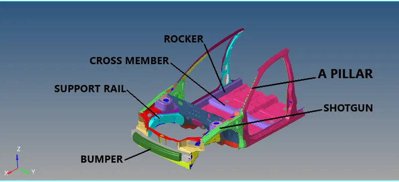
Import the model in the hypermesh, as you can see below the image it's not a full car model, this model comes with 100k nodes since the hypermesh student's edition supports till 100k nodes. This model consists of important BIW fixtures, so that limitation of the software license will not be exceeded.
MODEL:
UNIT SYSTEM:
We have to maintain the same unit system throughout the model because it leads to the wrong result after the simulation. we have to check the starter file before importing the model to hypermesh, so we came to know which unit system is applied on the model and we can change recommended units in the starter file. when I checked the starter file the units were kg mm ms.

COG/ MASS ADDITION:
Mass addition is an important factor that we need to assign before running the simulation. we have to keep the COG point in the middle of the model to attain good results. The center of gravity of any vehicle is the point that sums up the vehicle's mass in one central point. When making an analysis of the forces applied to the car, the COG is the point to place the car weight, and the centrifugal forces when the car is turning or when accelerating or decelerating. Any force that acts through the COG has no tendency to make the car rotate.
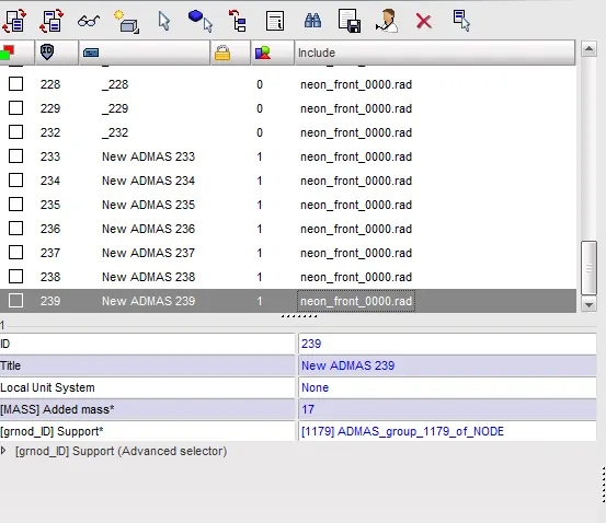
The total mass is 188 kg which is very less to run the simulation, and the COG point is at the dashboard. this is the actual mass present in the given model. we have to attain 700kg and the COG point in the cross member. so we have to add mass in the vehicle to get COG point in the cross member. the mass can be added in the hypercrash so that we can see the COG point clearly. In hypercrash go to Loadcase -> added mass to add mass in the vehicle. create a mass with type 1 so that mass will equally be distributed to selected nodes. give the required amount of mass and select the area to be applied.
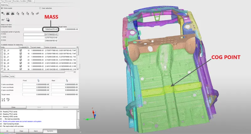
The COG point was shifted to the center of the cross member so that result would be realistic and the overall mass has been increased to 700 kg.
CONTACT INTERFACE:
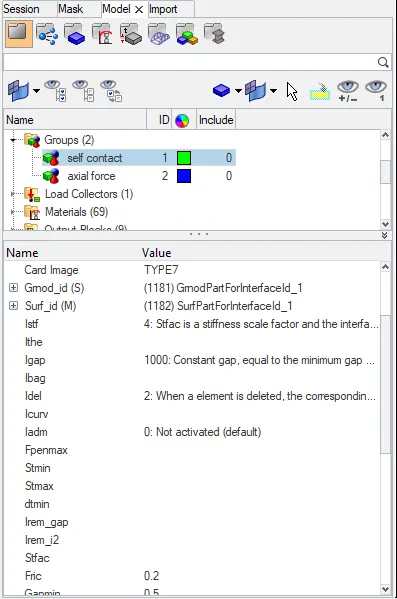
We have to create a contact in the BIW model. so that elements and nodes will get in contact with each other during the simulation. It is a required step to create an interface between them. I have decided to create a TYPE 7 contact with the recommended parameters. because type 7 is a node to surface contact. In hypermesh go to BCs -> create -> interface to create a contact interface. select the entire model for master and slave nodes to be a self contact.
RIGID WALL SETUP:
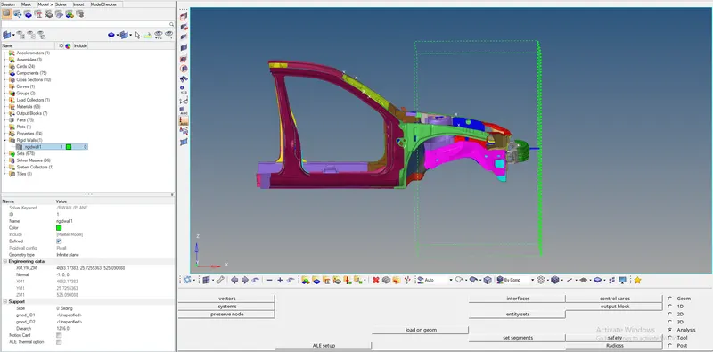
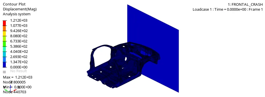
Rigid wall setup is an important step to be carried out. it allows the creating of an interface between rigid nodes and nodes of a deformable body. the rigid wall is part that will be lead to a crash of a present geometry. I have created an infinite plane rigid wall in front of the car so that the car model will get crash from the front side. I have given search distance as 1216mm from the rigid wall so that nodes present in the car will act as slave nodes and helps to crash as a real scenario against a wall. For setup go to BCs -> create -> rigidwall.
INITIAL VELOCITY:
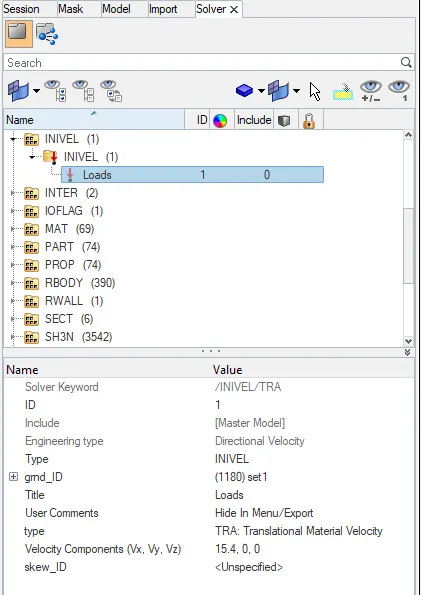
We have to mention initial velocity to the BIW car structure so that it moves given velocity and crashes to a rigid wall. I have given translational velocity with respect to X-axis. The given velocity is 35 mph which is converted into 15.4 mm/ms. for creating initial velocity go to solver-> create -> boundary conditions -> INIVEL .
SECTION CREATION FOR SECTION FORCE CALCULATION:
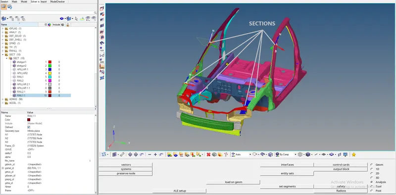
We have to create a section for calculating sectional force in the particular components. we have to select components and then we have to create a frame for local coordinates and then select a respective frame for a component. create a set for a group of elements present in the component for defining the shell id. we have to create sections for shotguns, A-pillar, rails. For creating a section go to SOLVER -> CREATE -> SECT. I have created 6 sections where we can find sectional force from them.
INTRUSION AND ACCELEROMETER SETUP:
We are selecting two nodes as intrusion points so that we can know the displacement of the node during the impact. The accelerometer option computes a filtered acceleration in a skew system. In addition to these filtered accelerations, the accelerometer also allows output to Time History, the integrals of X, Y, and Z raw accelerations projected onto the skew. We use skew as global coordinates. for accelerometer go-to model browser -> create -> accelerometer.
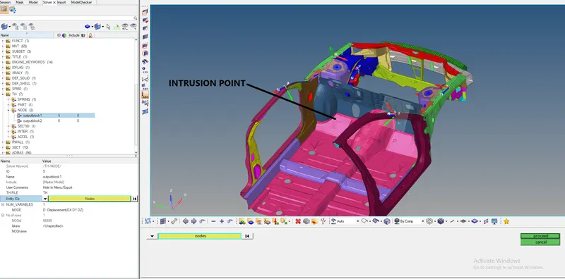
FIG: INTRUSION SETUP
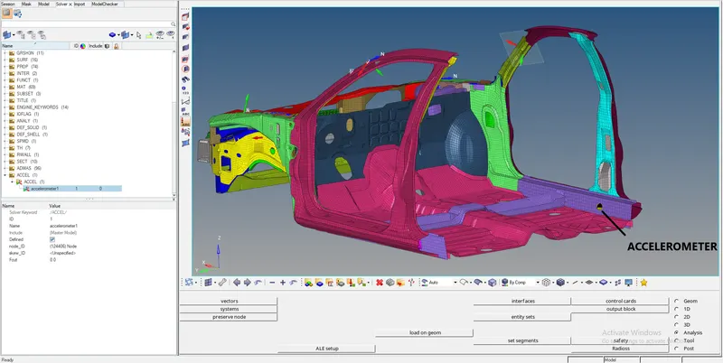
FIG: ACCELEROMETER SETUP
TIME-STEP :
The time needed for information to cross the smallest distance in an element. the computed time step is compared to a minimum time step value and a scale factor is applied to ensure a conservative bond. the time step can be controlled by three types CST, DEL, STOP. we use CST type because elements are switched to small strain formulation to maintain the constant time step. it will add some mass to the nodes to increase density. so that speed of the sound waves varies. the nodal time step is calculated after the computation of all internal forces at each node. for creating time step solver -> engine keywords ->DT -> DT/NODA. we have time step as 0.0005 ms and scale factor as 0.67.
OUTPUT REQUEST:
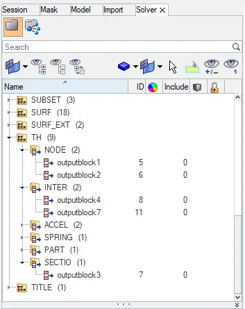
We have to create some output requests to check the forces act on the sections and few areas where intrusions and accelerometers are setups. To create an output request go to solver browser -> create -> TH -> INTER / NODE / SECTIO / ACCEL. output blocks are created for sections, intrusions, accelerometers, contact interface.
PENETRATION CHECK / MODEL CHECKER:
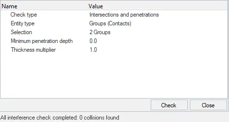
After defining the contact interface between nodes and elements, we have to check for initial penetrations and remove them before simulation. For penetration check go to TOOLS -> PENETRATION CHECK. select the group in which we want to check the initial penetration. I have selected 2 interfaces to check and there is no initial penetration present on the model.
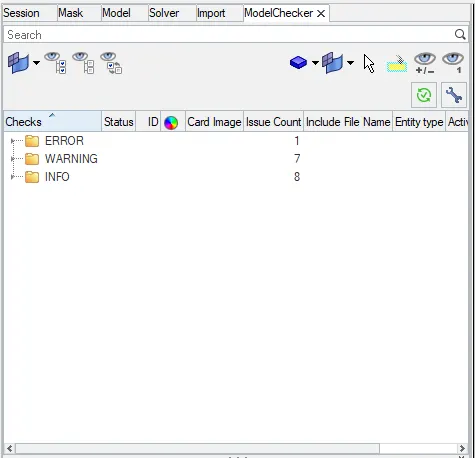
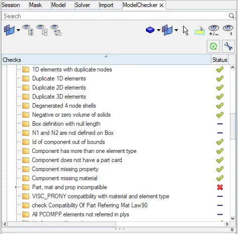
The model has to be checked before running the simulation. there will be errors and warnings after checking the model. errors need to be cleared and warnings can be ignored and some important warnings need to be cleared because they will lead to minor errors. In our model, there is 1 error which is a foam material card and it can be ignored.
RESULTS:
VON-MISSES STRESS ANIMATION:
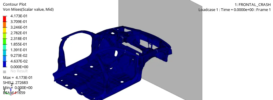
From the above animation, we came to know about the deformation in the model is more realistic. the deformation is more in the right side shotgun. maximum stress is 4.112E-01.
DISPLACEMENT ANIMATION:
ENGINE OUTPUT FILE:
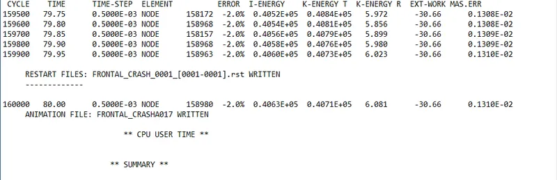
Energy error is -2.0% which is acceptable as per standard. the energy error is negative which indicates energy has been dissipated. mass error is 0.1310e-02. to compensate the mass which is added to nodes and registered as a mass error. as per standard mass error till 1% is acceptable. our simulation is stable as per results. the total simulation time is 2hr 19min 24sec.
ENERGY PLOT:
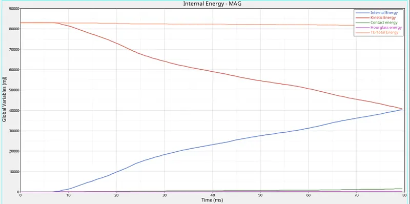
From the above graph, we can know about energy balance by plotting kinetic energy, internal energy, hourglass energy, contact energy. This graph shows that internal energy keeps on increasing and kinetic energy keeps on decreasing, this is because internal energy is inversely proportional to kinetic energy. there is no hourglass energy present since we have used QEPH formulation. the total energy is a summation of internal, kinetic, hourglass energy.
SECTIONAL FORCE:
SHOTGUN:
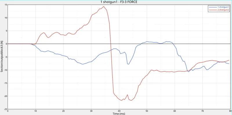
This graph shows that shotgun 2 receives a maximum force and deforms badly. since the graph fluctuates between positive and negative values, it is recorded based on local coordinates position. At the time of impact (10 ms) both shotguns receive force starts deforms. there is a sudden drop in shotgun 2 because it deforms badly. shotgun 1 receives less energy and deforms less than shotgun 2.
A-PILLAR:
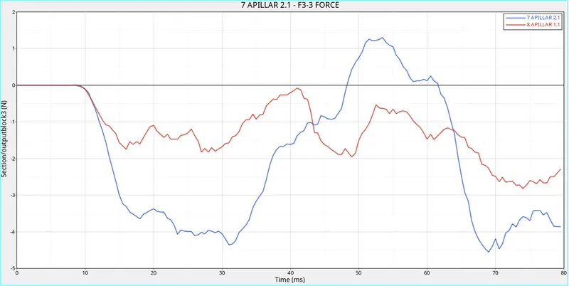
A pillar receives less force than shotguns because force will get distributed to all the parts. The impact will be more in the shotgun than A-pillar. A-pillar is positioned with some angle we have to create a frame and create a section. force is calculated in Z direction with local coordinates. vector changes its position while deforming. A pillar which is on the right side of the BIW component receives high energy and deforms badly than the other pillar. after 40ms there is a huge increase in the graph because A-pillar starts to bend during deformation.
RAIL FORCE:
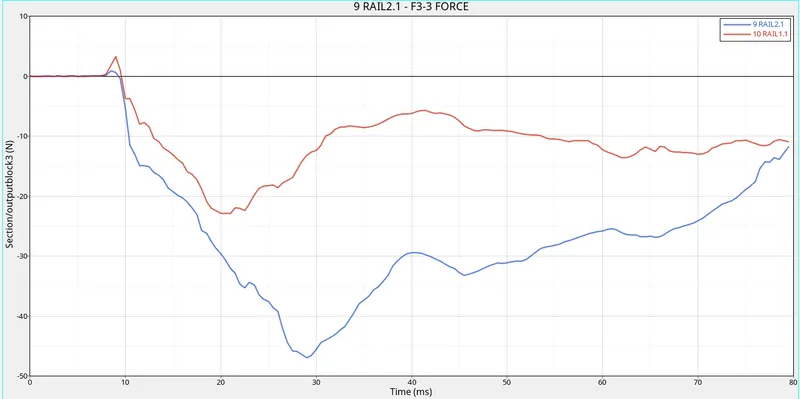
Force travels through rails is more than A-pillar, shotgun. because during impact bumper will receive maximum force and follows by rails. After 10ms both the rails receive force and get deforms at 20ms for right rail and 30ms for left rail. The deformation is maximum on the left rails because the force received on the left rails is more when compares with right rails.
AXIAL FORCE:
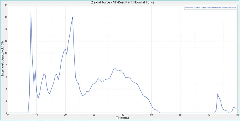
This graph shows how much force transfers from bumper to rails. The bumper plays a major role in the crash scene. It is the frontal part of the vehicle. when the vehicle crashes the first impact will be on the bumper. it will absorb maximum energy so that other components will not get much deform. as you saw in the above graph, maximum energy has occurred on the first impact and then energy decreases gradually. since bumper absorbs more energy.
ACCELEROMETER:
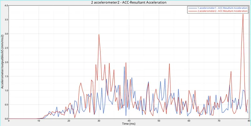
From the above graph, acceleration is recorded on the B-pillar rocker arms. this acceleration varies for each millisecond. because the deformation of the vehicle happens at various sides with different velocities. we can say that acceleration at the start time gets increases and decreases at the end.
CONCLUSION:
As a result, the simulation is stable after checking the engine output file. since bumper and shotgun rails absorb more energy, the force that travels to A-pillar is very less. More deformation occurs till shotgun. From this simulation, we know that there is less chance of injury to the passenger during a frontal crash.