Week 12:Project 2-Meshing of Rear Wheel Holder challenge
Aim:-
to mesh the given sheet metal component
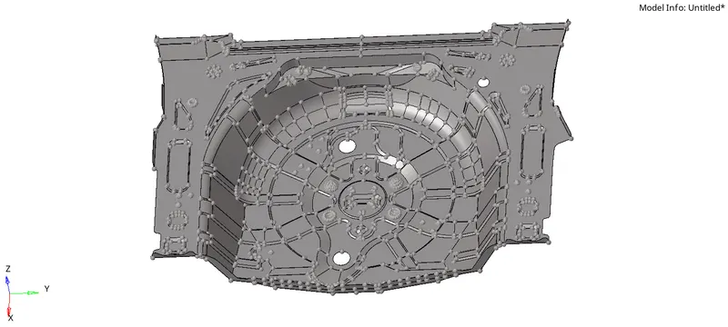
back wheel panel body
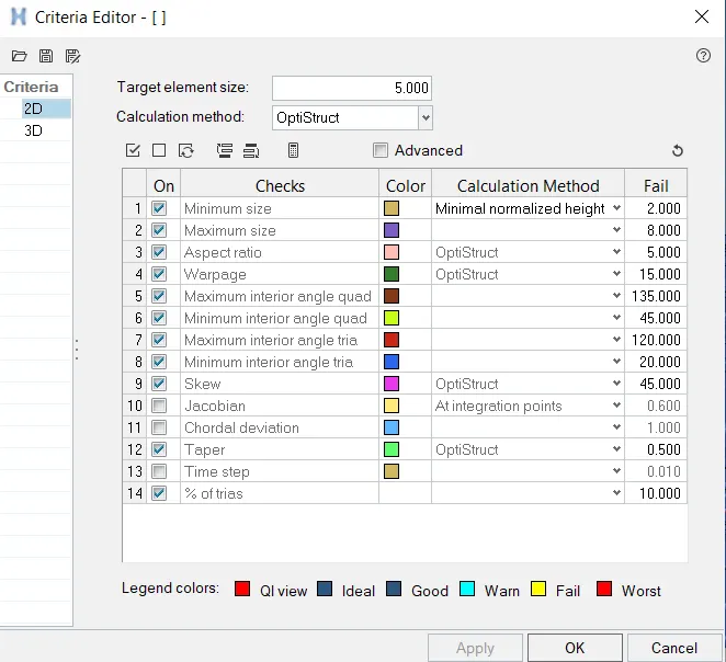
the mesh should follow the below criteria
| S.N | Quality Criteria | Value |
| 1 | Aspect Ratio | 5 |
| 2 | Skewness | 45 |
| 3 | Warping | 15 |
| 4 | Taper | 0.5 |
| 5 | Min. Length | 2 Units |
| 6 | Max. Length | 8 Units |
| 7 | Min angle Quad | 45 |
| 8 | Max angle Quad | 135 |
| 9 | Min angle Tria | 20 |
| 10 | Max angle Tria | 120 |
| 10 | Tria % | 10 |
procedure:
- as the given component int the form of .iges file format so, this can be imported into the graphics area by using the import geometry option
- import-import geometry-change file type.IGES file-select the file from its location -import.
step 1
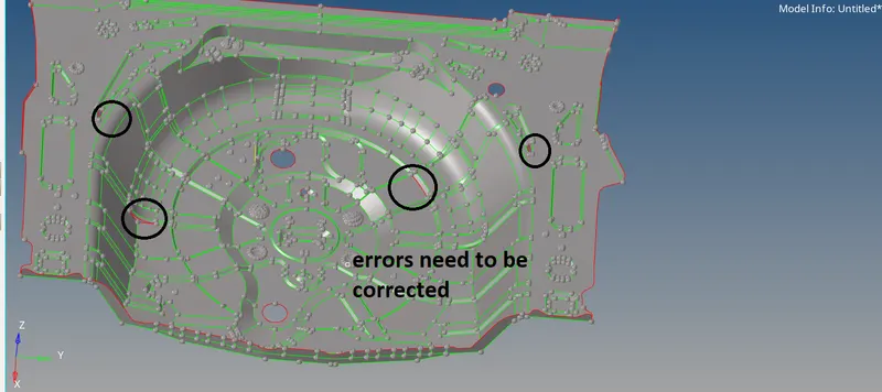
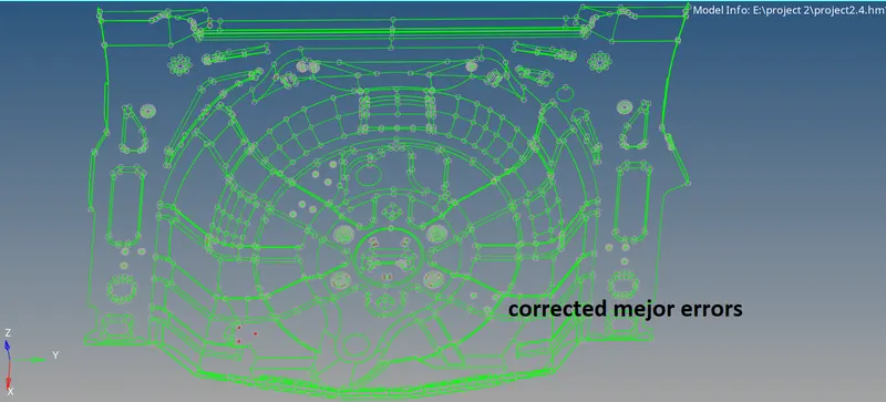
- check for surface errors which may show the effect on the creation of mid-surface by set changing it into the topo option. delete the surface that may cause distortion of the surfaces
step 2
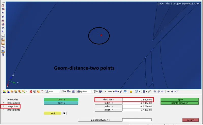
- measure the thickness of the component by using the distance option
- F4/Geom-distance-point to point option.
- to create points project option is used
- tools-project-to surface-select point(long press on the surface can create point duplicate it to project)-select the surface of target-set along vector as normal.
- heare we observed that the thickness of the component is uniform thought out the component and the value is 0.75mm.
before going to below step updating criteria and parameter files with require data may give expected results.
- preferences-criteria file editor-update the data-apply- ok
- preferences-parameter file editor-update the data-apply- ok

step 3
- we can conclude that given component is sheet metal because of its uniform thickness and also thickness less than 6mm
- we may can discratise the component by creating mid surface.
- there are two ways we can create mid surface.
- auto midsurface
- manual mid surface(offset)
- in this challenge mid surface is created by using auto mid surface option
- geom-midsurface-auto mid surface-change extraction option as offcet-select the surface in suto mid surface option -extract

extraction option(offset+planes+sweep)

extraction option(offset)
- above two options gives the same result
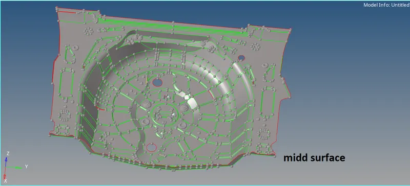
- here some portions are having surface errors this can be overcome by manual offsetting the surfaces(Geom-surface edit-offset-select the surface-enter the offset value according to normal direction-offset).
- the offseted surface can be connected by 'replace point' option(geom-quick edit-replace points).
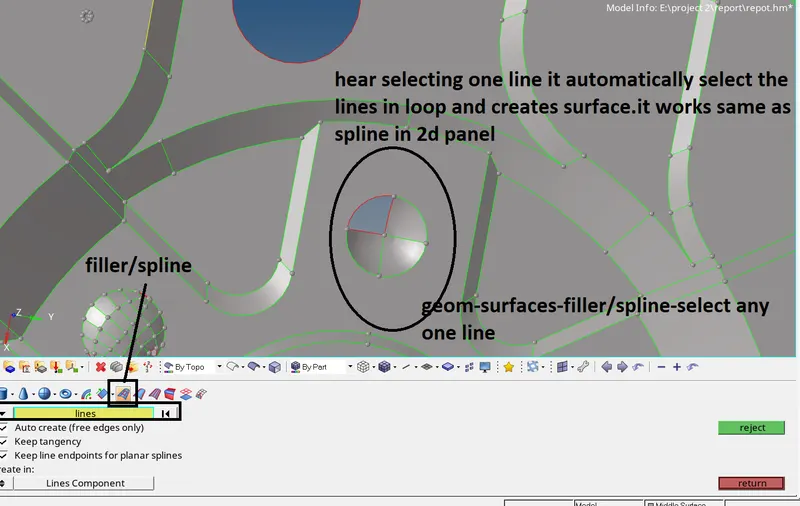
- we can also over come these surface errors by surface creation portions like ruled, spline(2d panel), filler surf option(quick edit panel), Ruled(option in geom-surfaces)
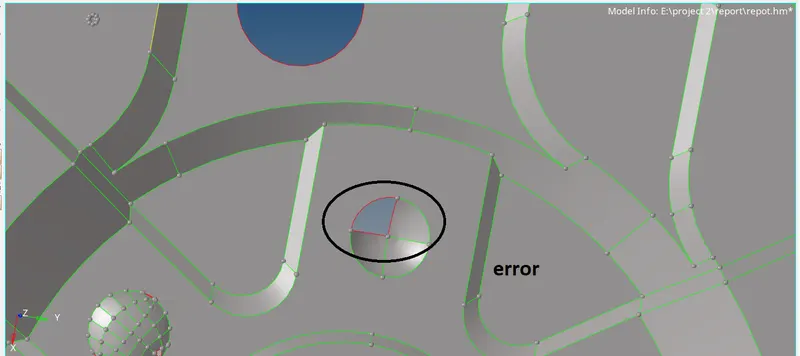
error
this can be solved in two ways as shown below
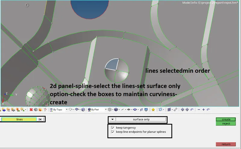
method 1
method 2
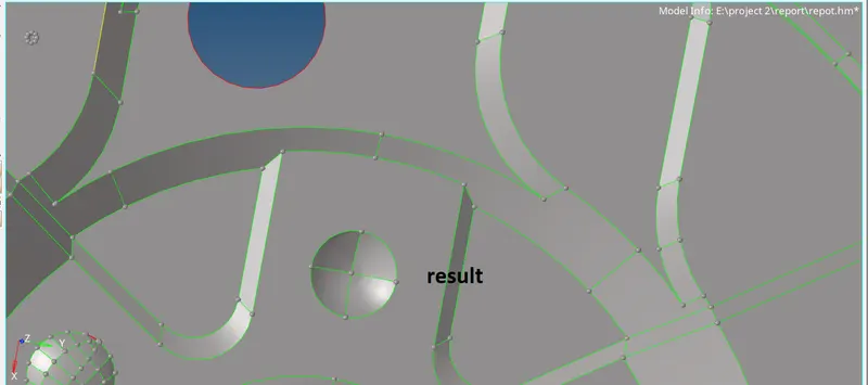
result for the above two methods
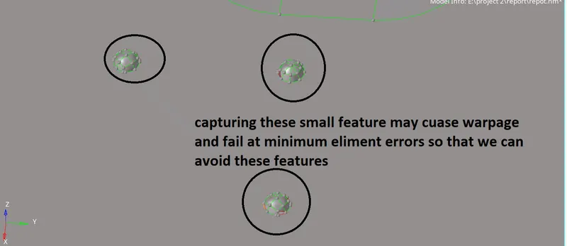
- features that are shown above are can be removed because of difficulty on capturing them.
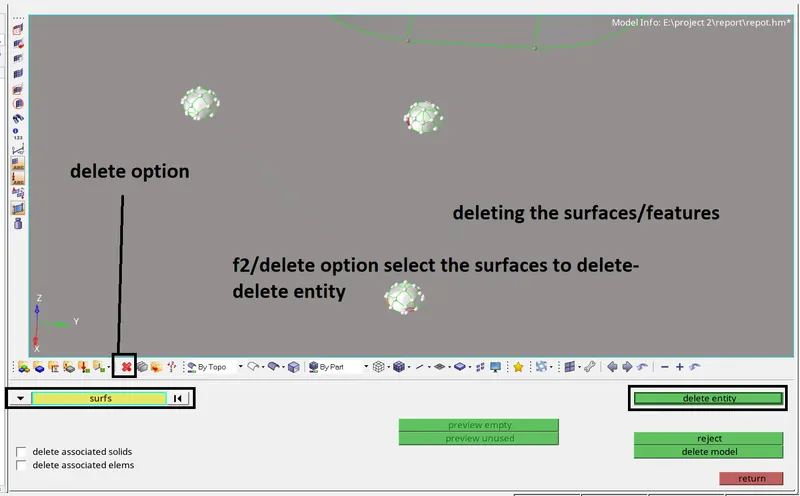
deleting the features
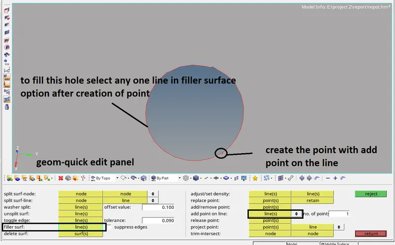
surface creation
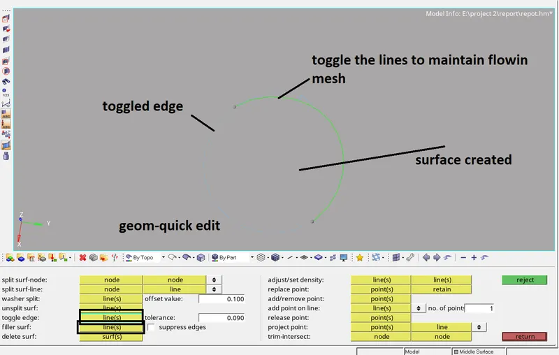
the result after deleting the feature
overall geometry clean up
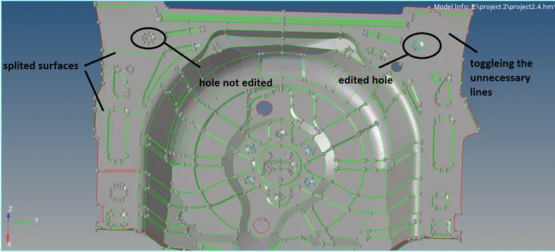
toggling and creating splits
step 4
- before meshing divide the surface into predefined shapes and also avoid sharp edges to reduce trias at corners as shown below
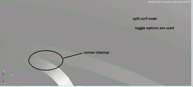
- mesh the surface one by one so that we can maintain flow in the mesh.
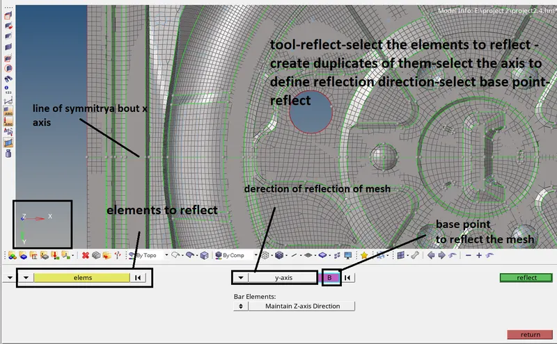
- on observation, we can find features that are similar to the perticular plane of the axis as shown below. by using the reflect option we can maintain symmetry in mesh flow and also save time
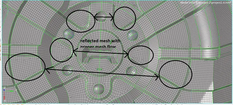
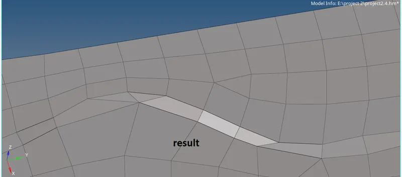
- reflected elements should be connected manually by replace or pre-equivalence option.
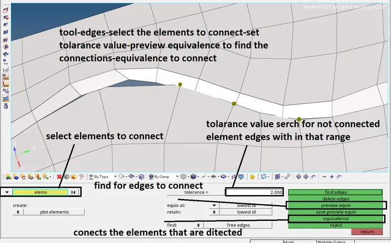
connection of reflected elements
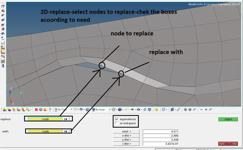
we can also connect the elements manually by the 'replace' option(2d panel-replace)
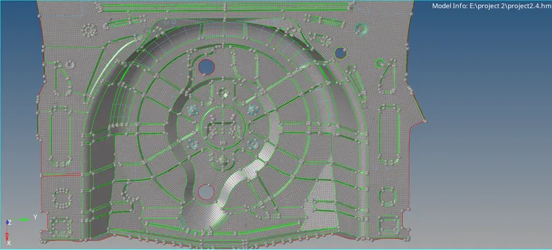
- overall meshed component
step5:-
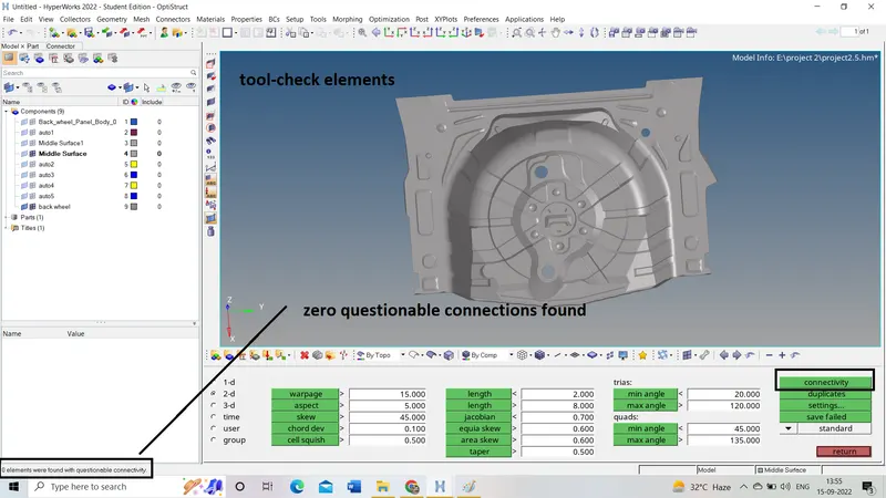
- there are different quality checks we should go on
1. check elements
int his we check for element quality criteria if any failed for it we solve it according to failing interest.
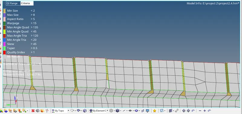
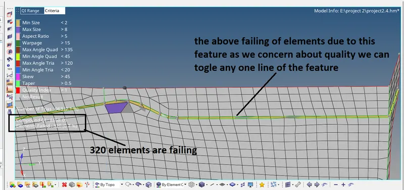
after toggling one of its edges and performing an element clean up option on the mesh
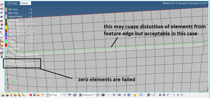

check elements panel
2. free edges
to check the connectivity of elements
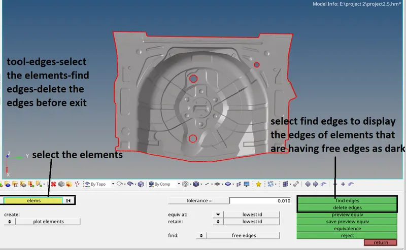
3. normals
in this we check for normal direction this may help in applying load on the component
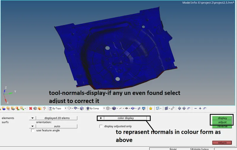
4. duplicates & penetrations
though this check we can know the presence of duplicate elements
these options perform only after finding free edges.
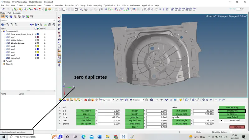
step 6
assigning thickness
- as the component given is sheet metal thickness will be uniform throughout the component. therefore we can hole components with the same thickness value. the thickness is 0.75mm for this component.
- first, create the property by right click-create-property-change the thickness value to 0.75mm.
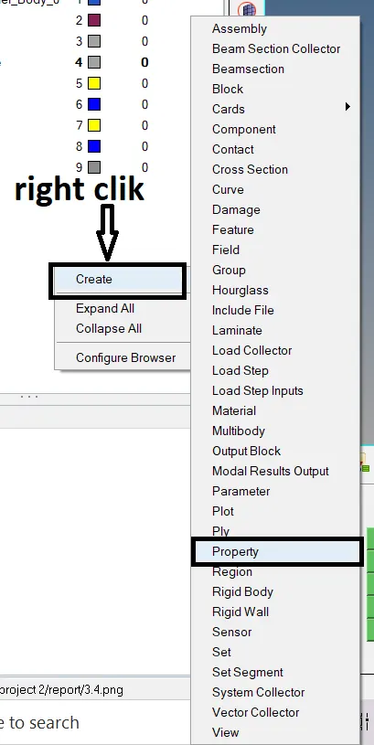
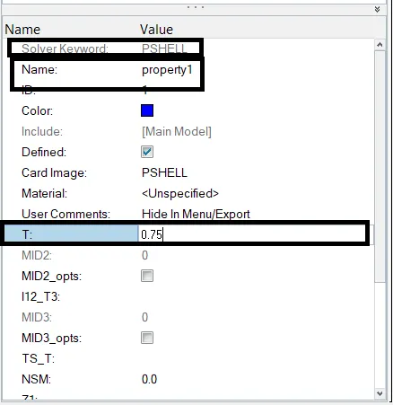
property creation
- then right click on the meshed component in the component tree-assign-select the property.
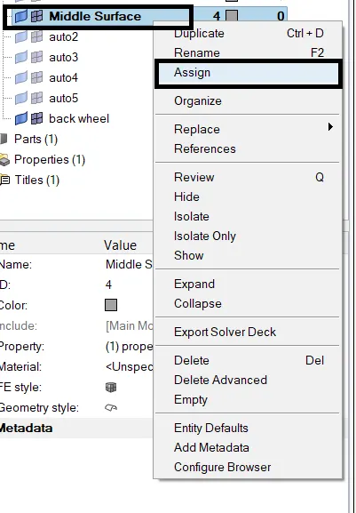
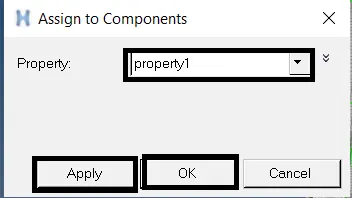
assigning property to the component
step 7
- after assigning the thickness we should check for its 2d representation on compared with parent geometry if it matches with parent geometry then the mesh will be accepted.
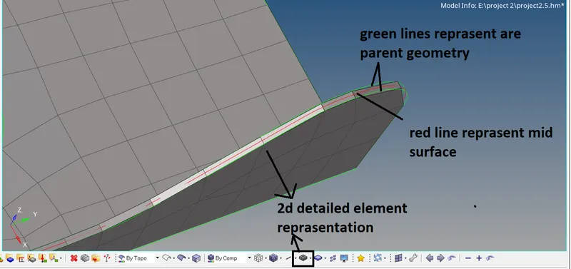
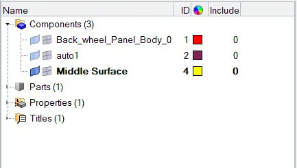
- organise the components by deleting unnecessary ones.
- tool-organise-select the destination component -select the surfaces to move -move and delete empty/unnecessary components
conclusion:-
another way of completing this challenge is through the batch mesh option.