Week 12:Project-1-Meshing of Door Inner Panel Challenge
Aim:
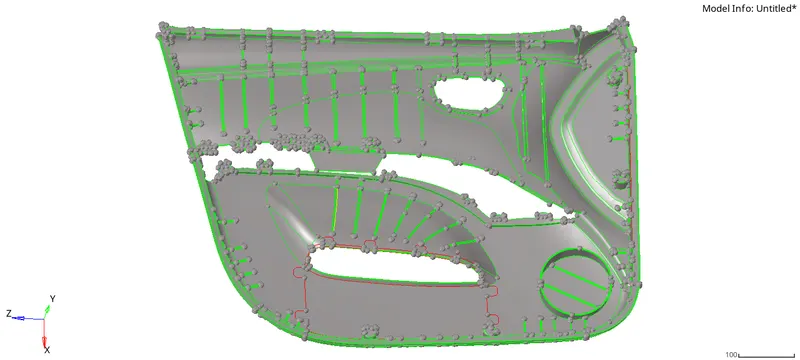
The meshing of given plastic component and assigning thickness to it
Procedure:
- The component is divided into base surface and inner surface
- Component of base surface has constant thickness
- Inner surface has ribs and some more features having different thicknes values.
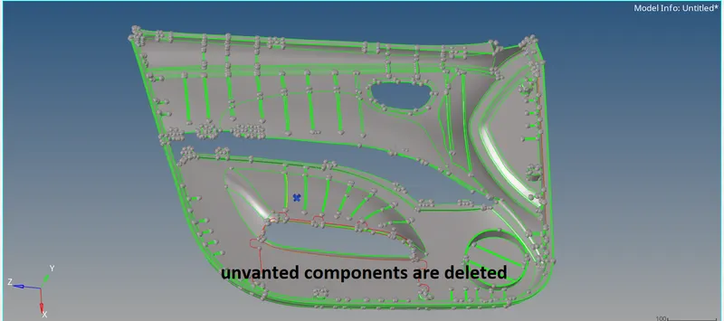
- check the thickness value at a different location if any slite variation take the average value.
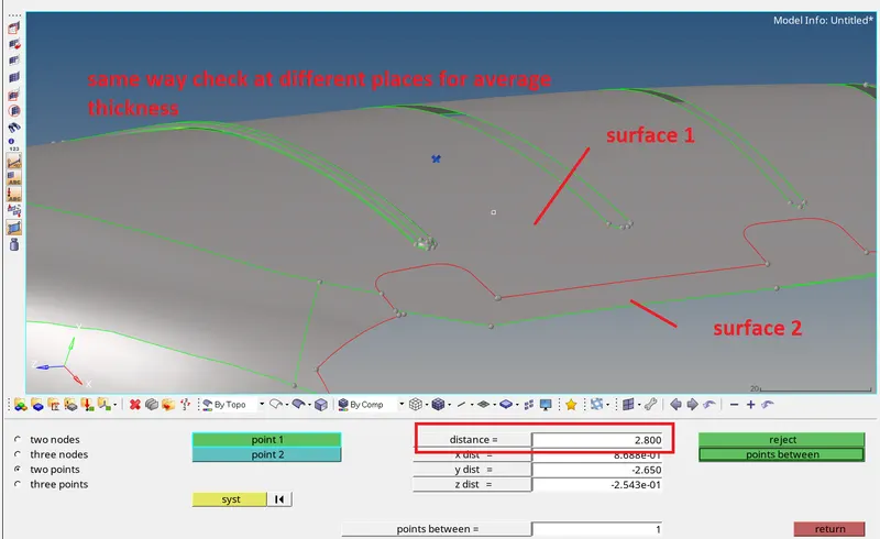
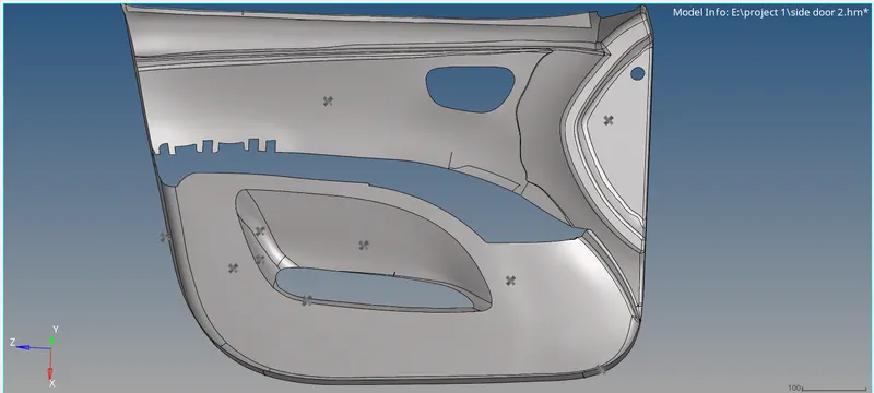
the base surface having a common thickness value
- Therefore in step 1 extract, the mid surface for base surfaces by using the manual mid surface creation method
- Geom-surface edit-offset-select the surfaces-duplicate surface into a new component created the enter the offset value.
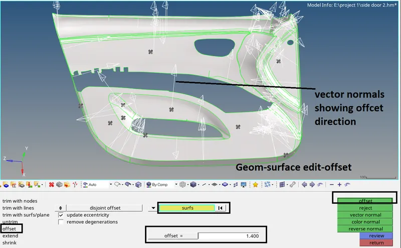
creation of mid surface
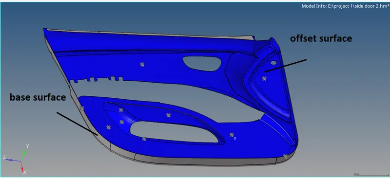
- check for the surface errors and connection of surfaces by using extent and toggle options.
- for ribs, the mid surface can be extracted by finding the midline (Geom-lines-midline)
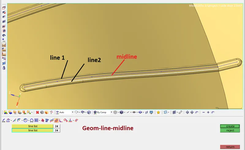
creation of midline
- project the midline to the base surface by using the project option(tools-project-select line to project-target as base surface)
- in this yellow line indicates the intersection of surfaces.
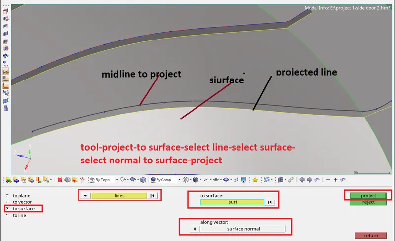
projection of lines
- the surface is created between these two lines by using the ruled option(Geom-surface-ruled-select the line-created)
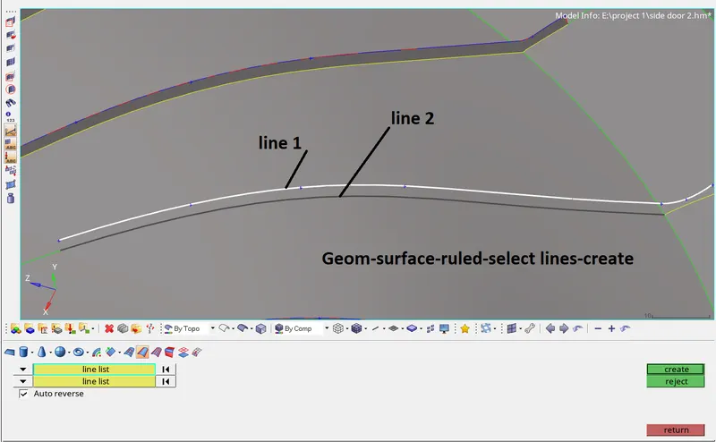
creation of mid surface for ribs
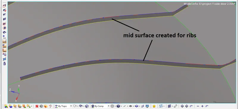
mid surface created
- there are some portions where this method will create a distorted surface there we can extract the surface by using the regular offset option.
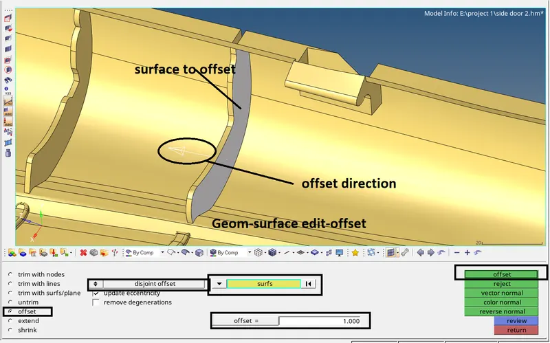
- after offsetting we should extend the surface to the base surface to make the connectivity between the surfaces based o the original ribs' connectivity. like as follows.
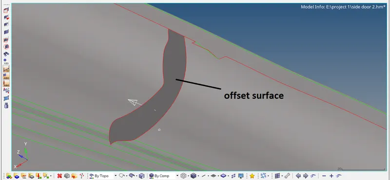
offset surface before Extention
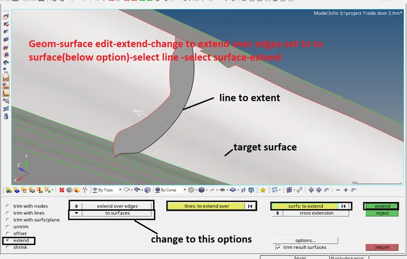
extension of edges
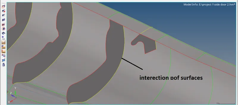
after Extention
- there are some features for which we can not extract mid-surface those can be represented as follows
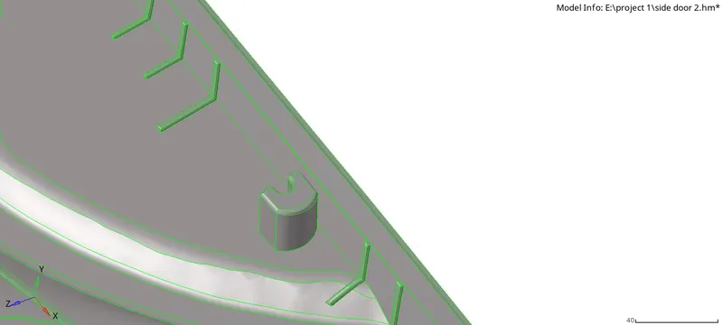
before feature to capture
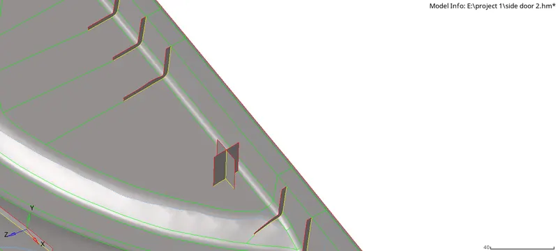
after capturing features
- some exceptional surfaces were extracted as shown in the problem.
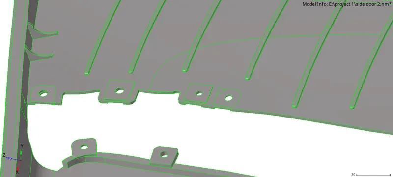
feature to capture
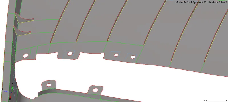
after capturing features
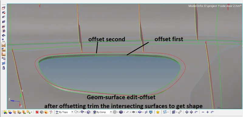
feature capturing
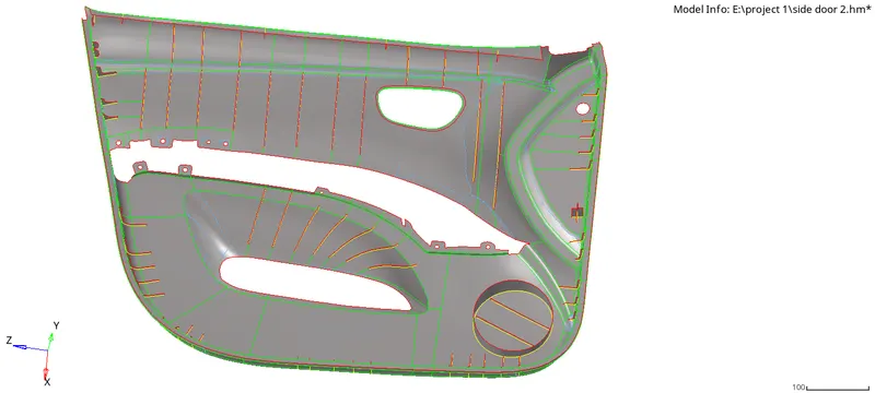
final mid surface
meshing:
- before meshing divide surfaces into predefined shapes to create proper mesh flow.
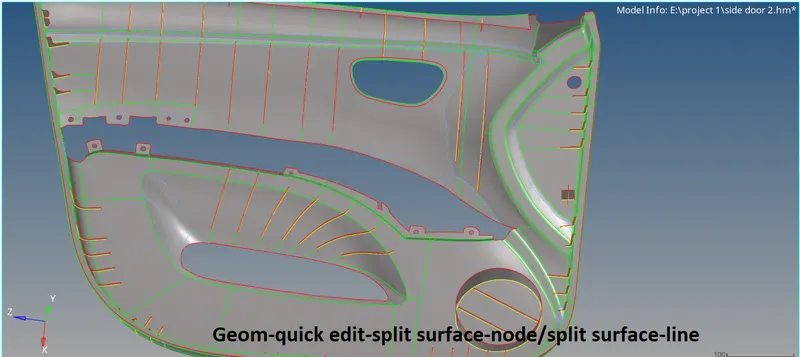
splitting of surface
- meshing starts with updating the parameter and criteria file as per the requirement.
the data for the criteria file is given in the problem below,
-
S.N Quality Criteria Value 1 Aspect Ratio 5 2 Skewness 45 3 Warping 15 4 Taper 0.5 5 Min. Length 2 Units 6 Max. Length 6 Units 7 Min angle Quad 45 8 Max angle Quad 135 9 Min angle Tria 20 10 Max angle Tria 120 10 Tria % 10
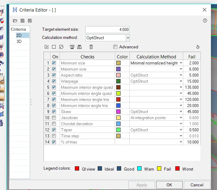
criteria file
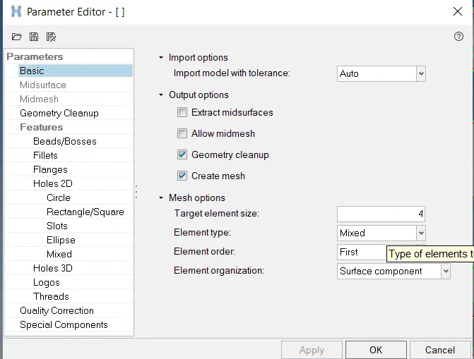
parameter file
preferences-parameter file/criteria file-save for future use.
- updating these files helps while using rebuild mesh options.
- the meshing is done with the auto mesh option and is performed on surfaces individually to get proper mesh flow and connectivity.
- the below option helps in clearing failed elements.
- edit elements(2D-edit elements) (through which we can create, combine and slit the elements according to requirement)
- element cleanup(2D-element cleanup)(reset the failed elements according to the criteria file that we updated earlier)
- rebuild mesh (2d-rebuild mesh)
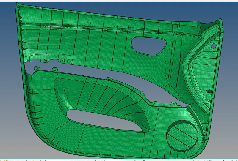
final mesh
checks
- after meshing we should perform some checkings
- quality check(2D- quality index)
if elements are failing for any criteria we can correct it by using cleanup tools(present in the quality index option itself),elem cleanup(2D-
elem cleanup),rebuilding mesh(2D-rebuild mesh)
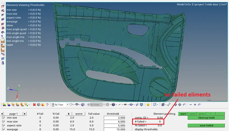
checking element criteria
2. free edges(tools-edges)
we should check for free edges. through this, we can find the connectivity of elements
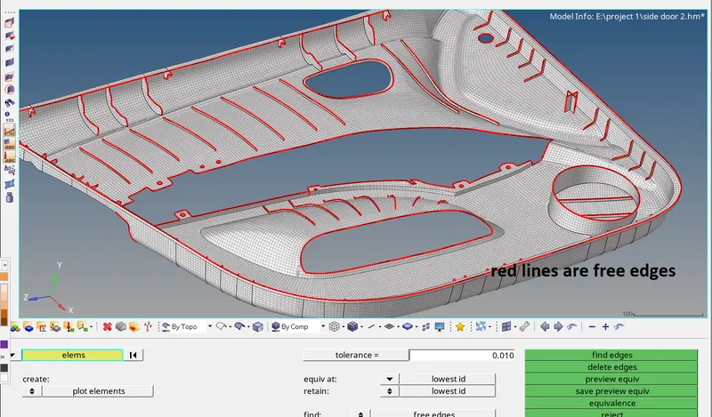
edges
3. presence of duplicate elements
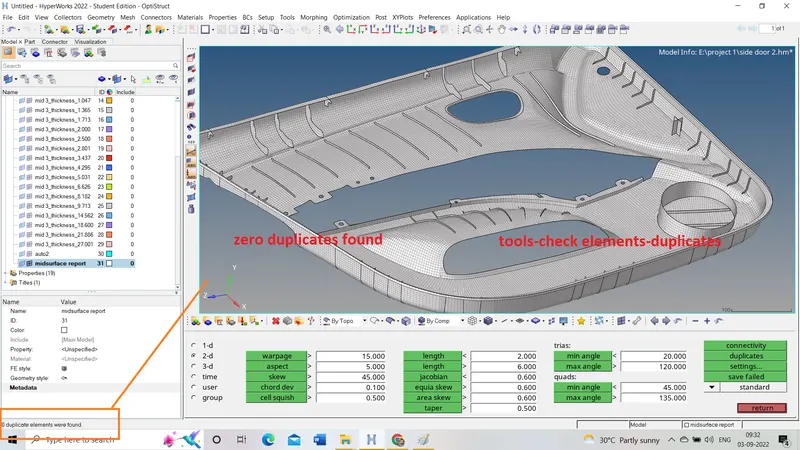
duplicate elements
if any duplicates are found ave they failed and by retrieving in delete option delete them. then again check for duplicates until all clears.
4. connectivity
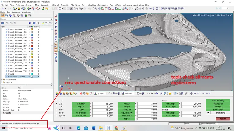
checking questionable connections
if any connection errors are found connect the elements by using replacing the nodes(2D-replace) option.
5.normals
if normals are displayed non-uniformly try for adjust option, still exits the error manually select the elements(to select elements change display 2D elements to elements) that display the normals and reverse it.
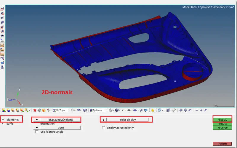
check for normals
6. penetration(tools-penetration)
this error occurs when the elements intersect with each other
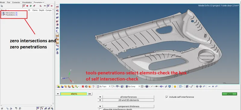
check for penetrations
assigning thickness:
- In two ways we can assign thickness to the shell elements
- manual method
- automatic
- in the manual method, we need to create components and properties separately for each feature having a particular thickness.
- first, measure the thickness of the feature to assign thickness by using the distance option(F4/Geom-distance-between two points these points should be created by projecting one point on the other side to get the exact perpendicular distance.)
- then separate the shell elements' particular future to the respective component and assign the property with the respective thickness created in the property tree.
- the same method is applied for each feature having a varying thickness
- and automatic assign of thickness to the component
- follow the below steps to assign the thickness
Mesh-assign-mid mesh thickness-(a window will pop up)-change solid to surfaces(in this select the parent surfaces of the component so, that it can calculate thickness)while selecting surfaces turn of mid-surface-proceed-then select elements-in thickness output section select properties on components( this option creates components for features of different thickness values separately and organise the elements into that components and also creates property components according to them separately. )-set value of maximum thickness range interval(better to live it as default if we want we can change it.)-calculate thick ness-close.
- in its project, I followed the second method to assign thickness, though this we can save a lot of time but have to sacrifice accuracy
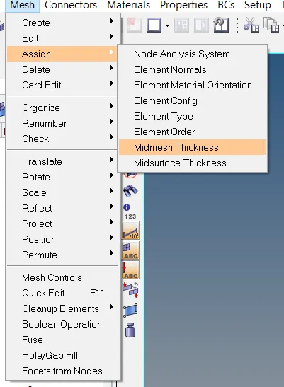
fig1
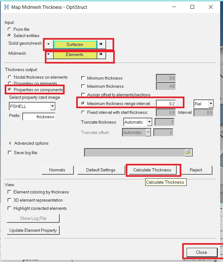
fig 2
in fig 2 in the input section select the parent surfaces to allow the system to calculate thickness and in the elements option select the elements.
in the thickness output section check the box for properties on components, then check the maximum thickness interval and go for calculate Thickness.
The below figure shows the components created automatically with respective thickness values.
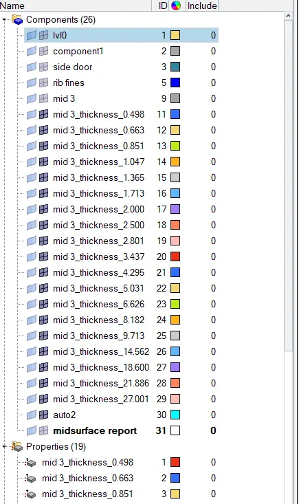
fig 3
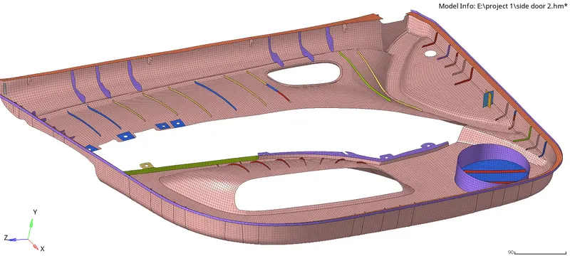
elements are represented with respect to their thickness
to check whether the thickness assigned is correct or not change the option from 2d traditional representation of elements to 2D detailed representation of elements as shown below.
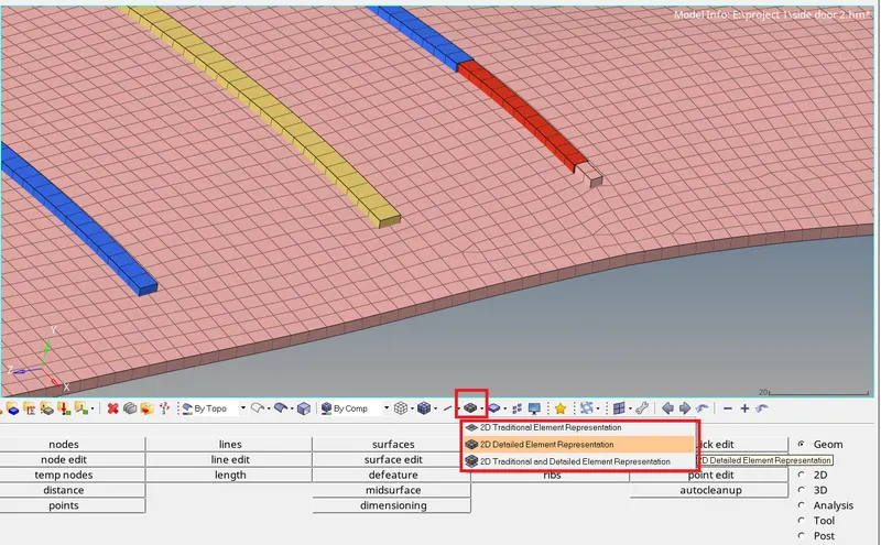
2D detailed representation
by changing to this option we are able to represent the elements having a thickness.
if the elements are assigned to improper thickness values we can measure the actual thickness from parent geometry and organize(tools-organize-select the elements-select the component change into-move) them into respective components.
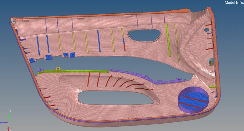
project 1