Shock Simulation in SCRAM Jet
SCRAM JET
A great man once said, “The Faster, the better”. I don’t know who quoted this, but, if no one did it yet, I should probably copyright this line.
SCRAM Jet’s were invented to do this exactly, i.e, move faster. SCRAM jets stand for Supersonic Combustion RAM jet’s. Both SCRAM and RAM jets do not have any rotating parts, which give them many advantages. For example, they are not limited by the turbine blade’s material properties.
The principle is simple. High supersonic air or Hypersonic air enters into the Engine, it is lowered to (Low) Supersonic speeds in inlet through shockwaves, fuel is injected, flame holders ignite the fuel and boom. Tons of Energy is converted from chemical energy to thermal and kinetic energy. The combustion products rapidly exit through the nozzle and into the atmosphere, thus generating thrust from Newton’s third law.
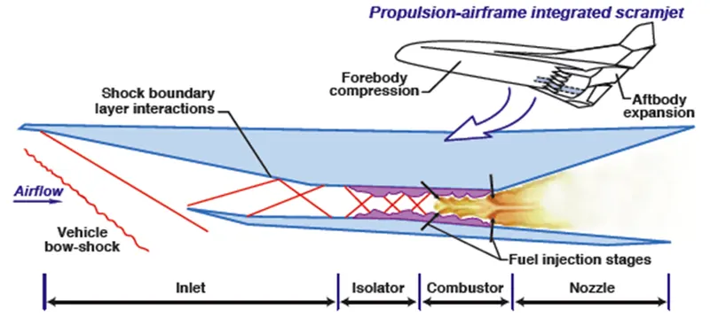
Usually, these engines are lengthy so as to allow complete combustion of air and fuel. But, a longer engine = More losses and less efficiency. Continuous research is being done in this field so as to reduce the engine’s overall length.
Some ways to achieve it is using wall cavities and fuel injection techniques. Wall cavities help in increasing turbulent mixing of the fuel with air by creating recirculation zones and thus reducing ignition time delay. Combustion efficiency can be varied by varying the fuel injection angle and wall cavity geometry. The current project/Article will focus on these two techniques and compare combustion efficiency for various cases.
Do watch the following videos to visualize these concepts.
Simualtion in Ansys
Model
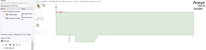
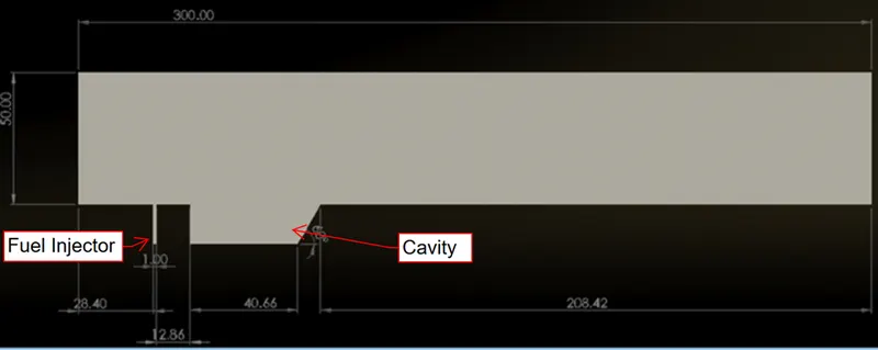
The model was made in Ansys SpaceClaim. Parameter's were created for Fuel Injector angle and Cavity Angle.
Mesh
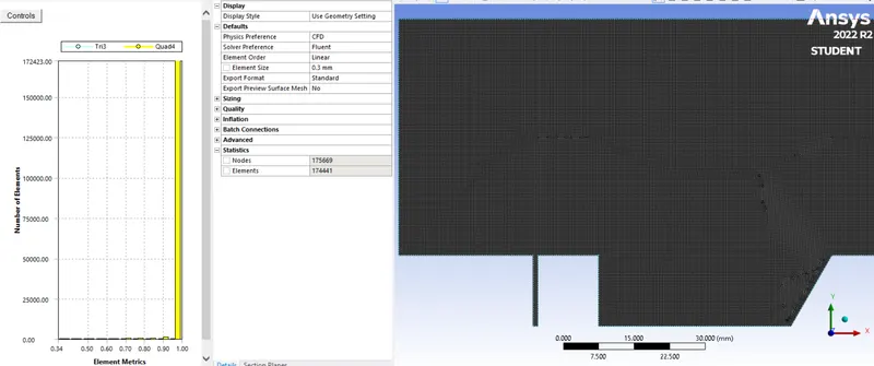
Set-Up
Before going through the set-up, I highly suggest you to go through the paper "NumericalInvestigationontheEffectofInflowMachNumberson the Combustion Characteristics of a Typical Cavity-Based Supersonic Combustor". This research paper will help one understand the concepts more clearly and also will help us to decide the boundary conditions.
- Type - Density based
Supersonic flows are highly compressible and thus a density based solver is used. This essentially means that density will be caluclated from the N-S equation rather than Ideal gas equation. - Velocity formulation - Absolute
- Time - Steady
- Models
Energy - ON
Viscous - k-Omega SST
Species - Species Transport, Volumetric - Materials - Air (fluid), Air-Hydrogen (mixture)
Note - Density formulation must be choosen as Ideal gas (By default it is constant or incompressible Ieal gas)
Before going any further, do watch this video to understand about Boundary conditions for Super Sonic flows.
- Boundary Conditions:
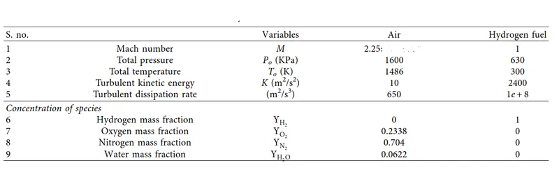
Air Inlet - Far Field Pressure inlet
Fuel Inlet - Pressure Inlet
For the above two boundaries, the gauge pressure must be calculated from isentropic relations.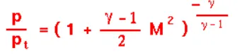
It is advisable to keep turbluent intensity and turbluent viscosity ratio as 1 for supersonic flows. - Operating Condtions - Pressure = 0
- Method - IMPLICIT
Flux - AUSM
Higher order RElaxation - All vriables = 0.25
(This information has been obtained from Ansys tutorials for Supersonic simulations) - CFL number - 10
Limits - Positivity rate limit = 0.05
(This information has been obtained from Ansys tutorials for Supersonic simulations)
Results
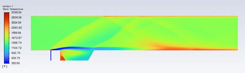
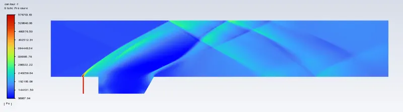
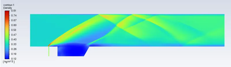
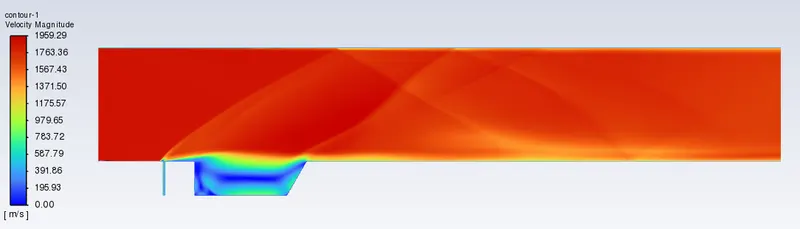
For a fuel injection angle of 90 degrees and wedge angle of 60 degrees.