Week 12- Major Project (CFD Analysis on Combustion in a SCRAMJET engine)
Aim
Conduct simulations of supersonic combustion in the given combustor geometry. Further, identify the best configuration to get the highest combustion efficiency by varying the wedge and fuel injection angles.
Introduction
The development of hypersonic airbreathing vehicles (M>5) is often dependent on the capability of supersonic combustion technologies. Subsonic combustion prevalent in the engines used in supersonic vehicles cannot produce the required thrust in the very short time required to propel hypersonic vehicles. This brings in the need for extensive research on supersonic combustion and identifying ways to maximize its efficiency and thrust. The scramjet engine is one such technology in development that can perform supersonic combustion. The major problem with the scramjet engine is the increased size requirement of the combustor. Since the fuel and air mixture travels at very high speeds, the fuel molecules do not have the time to completely mix with the air and ignite before exiting the combustor. This incomplete combustion often leads to lower combustion efficiency and should be addressed. One method of improving mixing and reducing the ignition delay is by using cavities in the combustor as a method of flame holding. These cavities when aligned well with the fuel injectors may help to drastically increase the combustion efficiency without needing to increase the length of the combustor.
The combustion efficiency is defined as the ratio of burnt fuel to injected fuel, as used in the works of Choubey et al [1], given as:
`eta_{CE} = 1 - (dot m_(f_(burnt fuel)))/(dot m_(f_(fuel)))`
The combustion of fuel in air is dependent on the equivalence ratio as in defined as the ratio of the actual fuel-air ratio to the stoichiometric fuel-air ratio given as:
`phi `= (Actual Fuel-Air Ratio) `/ `(Stoichioemtric Fuel-Air Ratio)
phi< 1 implies a fuel-lean mixture
phi>1 implies a fuel-rich mixture
phi =1 implies a stoichiometric mixture
Method
Simulations were conducted using 2D simplifications for a variety of cases involving variation in the wedge angle of the cavity, fuel injection angle, and placement of the fuel injector. A total number of 14 cases were run for this analysis to identify the configuration with the highest combustion efficiency.
Domain and Mesh
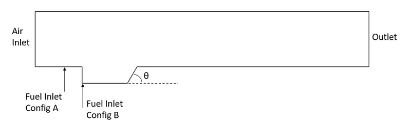
The design of the combustor was provided and can be seen in the schematic below. Two configurations involving the fuel injector placed upstream of the cavity and in the cavity were analyzed. Additionally, variations in the fuel injection angle and the wedge angle of the cavity were also simulated to identify the best combustor design to maximize combustion efficiency.
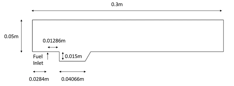
The detailed dimensions of the 2D combustor domain can be seen in the image below. The height of the cavity D= 0.015m is taken as the characteristic length of the combustor. The L/D ratio of the given combustor is 20.
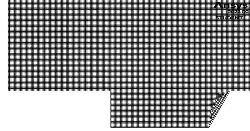
An unstructured quad-dominant mesh was generated over the domain. The element sizing was set to 5e-4m for the domain and resulted in a total of 445k mesh elements. The image below shows the zoomed-in view of the mesh for the 60degree wedge angle case. The 45degree and 30degree meshes were generated similarly to the one shown.
CFD Setup
All Simulations were conducted using Ansys Fluent 22 R2. The fluid used in the domain was the predefined hydrogen-air mixture for the global step combustion mechanism. The density of the individual species was estimated using the ideal gas formulation. The air and fuel inlets were set to a pressure inlet with a pressure outlet at the rear. The operating conditions were set to 0Pa. The injection fuel injection angle was varied for the respective simulation using components.
The detailed boundary conditions were derived from the works of Wang et al[2] and can be seen in the table below.
| Parameter | Inlet Air | Inlet Fuel |
| Mach | 2.52 | 1.0 |
| Total Pressure | 1.6 MPa | 0.8 MPa |
| Total Temperature | 1486 | 300 |
| Mass Fraction `O_2` | 0.2338 | 0 |
| Mass Fraction `H_2O` | 0.0622 | 0 |
| Mass Fraction `N_2` | 0.7040 | 0 |
| Mass Fraction `H_2` | 0 | 1 |
Using the above boundary conditions resulted in the equivalence ratio of the combustion: `phi`= 0.62.
The steady-state pressure-based PV-coupled solver was used for the spatial discretization of the flow parameters. The energy equation was enabled for the simulation. Turbulence was estimated using the two-equation K-Omega SST turbulence model. The volumetric reaction kinetics was modeled using the finite-rate/eddy-dissipation model. The second-order scheme was used to estimate the pressure, the second-order upwind scheme was used to estimate momentum, energy, species, and turbulence parameters. The solution was initialized using standard initialization followed by an FMG initialization to quicken the simulation runtime. The pseudo-transient method was also used with an automatic conservative length scale.
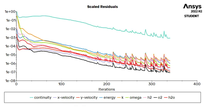
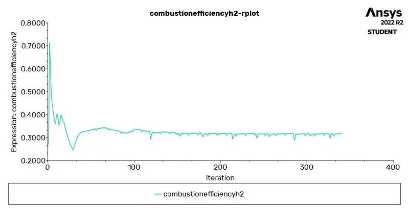
Convergence was monitored using the scaled residuals and the variations of combustion efficiency across iterations. The simulations were assumed to be converged when the combustion efficiency varied under 0.001 across 10 iterations and scaled residuals were all below 1e-3. The simulation typically ran for 300 iterations to achieve convergence.
Results
The typical convergence of the scaled residuals and the combustion efficiency can be seen in the images below.
The results of the combustion efficiency for the various cases can be seen in the table below.
| Case no. | Wedge Angle | Injection Angle | Injector Position | Combustion Efficiency % |
| 1 | 30 | 90 | Before Cavity | 21.28 |
| 2 | 45 | 90 | Before Cavity | 21.68 |
| 3 | 60 | 90 | Before Cavity | 22.23 |
| 4 | 60 | 60 | Before Cavity | 26.17 |
| 5 | 60 | 45 | Before Cavity | 28.01 |
| 6 | 60 | 30 | Before Cavity | 33.47 |
| 7 | 60 | 20 | Before Cavity | 36.40 |
| 8 | 30 | 90 | At Cavity | 31.80 |
| 9 | 45 | 90 | At Cavity | 31.20 |
| 10 | 60 | 90 | At Cavity | 29.94 |
| 11 | 60 | 60 | At Cavity | 47.57 |
| 12 | 60 | 45 | At Cavity | 62.83 |
| 13 | 60 | 30 | At Cavity | 78.44 |
| 14 | 60 | 20 | At Cavity | 62.44 |
From the above table, case 13 with a fuel injection angle of 30 degrees, 60 degrees wedge angle, and in-cavity fuel injector has the highest combustion efficiency of 78.44%. A steady increase in combustion efficiency can also be seen in decreasing fuel injection angles. When the injection angle is maintained at a const 90 degrees, increasing the wedge angle is shown to increase the combustion efficiency in cases where the injector is before the cavity, but decreases combustion efficiency when the injector is placed at the cavity. Overall, the placement of the injector inside the cavity shows higher combustion efficiency in all cases compared to the corresponding cases of the injector placed before the cavity.
The images below show the Mach no distribution from case 13 (top) with the best combustion efficiency and case 1 (bottom) with the lowest combustion efficiency.
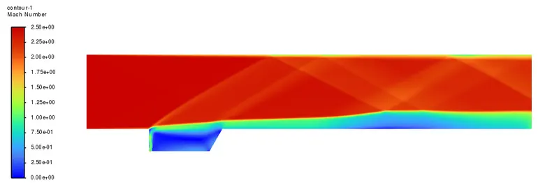
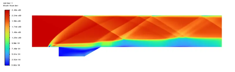
Oblique shocks can be seen emanating from the shear layer in both cases reflecting between the upper walls and the shear layer. Case 1 has more oblique shocks and reflections compared to case 13 and can be attributed to the fuel injection flowing transverse into the free stream supersonic flow creating a large obstruction to the flow.
The images below show the static temperature distribution from case 13 (top) with the best combustion efficiency and case 1 (bottom) with the lowest combustion efficiency.
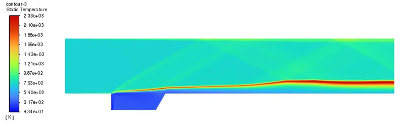
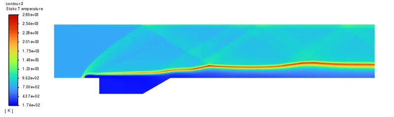
The highest temperature can be seen in case 1 to be 2800K while case 13 reaches a maximum temperature of 2330K. These rises in temperatures strongly indicate the occurrence of supersonic combustion in the supersonic flow.
The images below show the mass fractions distribution of H2 and H2O from case 13 (top) with the best combustion efficiency and case 1 (bottom) with the lowest combustion efficiency.
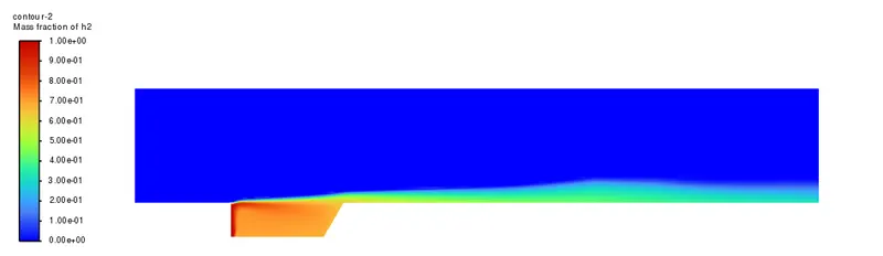
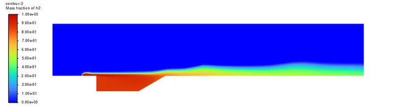
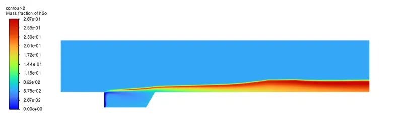
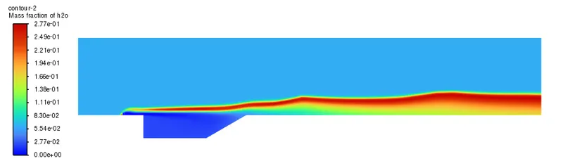
A steady decline in the mass fraction of H2 and an increase in the mass fraction of H2O can be seen downstream of the cavity in both cases. The traces of unburnt H2 at the outlet is seen to be more in case 1 compared to case 13 and this directly leads to the difference in combustion efficiency. A similar trend is seen for the mass fraction of H2O at the outlet as well.
Conclusion
Simulation of supersonic combustion was conducted using the given cavity-based combustor geometry with varying wedge angle, fuel injection angle, and fuel injector positions. The combustion efficiencies of all the cases were compared to arrive at the best configuration. The combustor configuration with a 60 degrees wedge angle, 30 degrees fuel injection, and the injector placed inside the cavity showed the highest combustion efficiency of 78.44%.
References
- Gautam Choubey, K.M. Pandey, Effect of variation of inlet boundary conditions on the combustion flow-field of a typical double cavity scramjet combustor, International Journal of Hydrogen Energy, Volume 43, Issue 16, 2018, Pages 8139-8151, ISSN 0360-3199, https://doi.org/10.1016/j.ijhydene.2018.03.062.
- Hongbo Wang, Zhenguo Wang, Mingbo Sun, Ning Qin, Large eddy simulation of a hydrogen-fueled scramjet combustor with a dual cavity, Acta Astronautica, Volume 108, 2015, Pages 119-128, ISSN 0094- 5765, https://doi.org/10.1016/j.actaastro.2014.12.008.