Week 12- Final project
AIM:
- To design the car door inner panel with the given input class A surface by the help of mastersection
- To create attachment features on the class B surface as per proper guidelines for them.
- To perform draft analysis.
OBJECTIVE:
The project deals with the detailed explanation of procedures followed to design and develop the door trim inner panel of a car. Here the class A surface, class B surface and class c surfaces are created with the given reference along with the tooling axis. Then the attachment features ( ie., Flanges, Heat Stacks, Dog Houses, Four way locators, Pish Pins) were created and finally draft analysis were performed to check the manufacturing feasibility.
METHODLOGY:
The methods followed for this project is as below
- Class A surface was created from the given reference surface.
- Tooling axis were created on the class A surface individually.
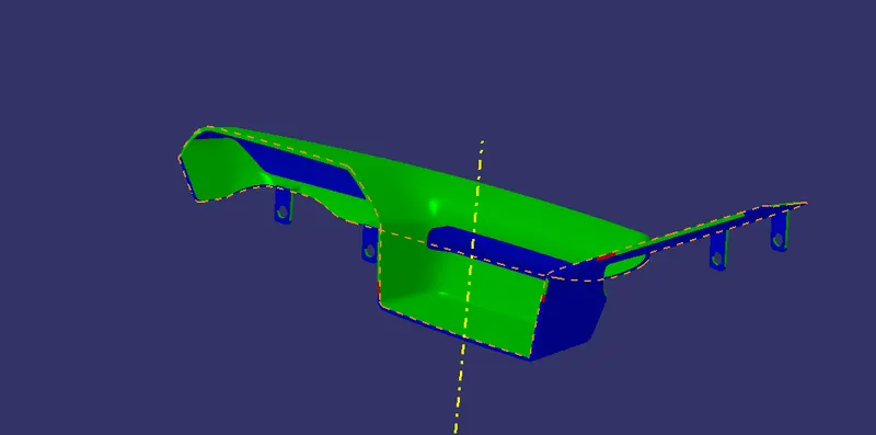
- Feature draft analysis was performed on the class A surface.
- Class B and class C surfaces were created with proper guidelines.
- Closed body were obtained by all three surfaces with the help of trim freature.
- Created solid body and performed draft analysis on the it.
- Engineering features were created for attachment on the class B surface.
- Draft analysis were proformed on the engineering features.
PROCEDURE
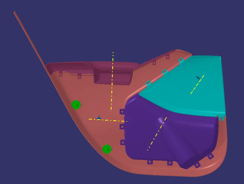
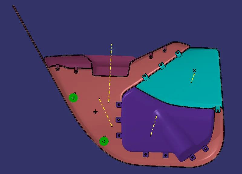
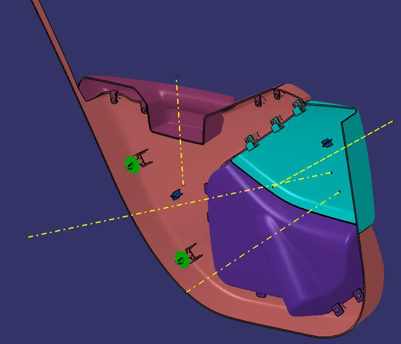
Given reference surface with Mastersection.
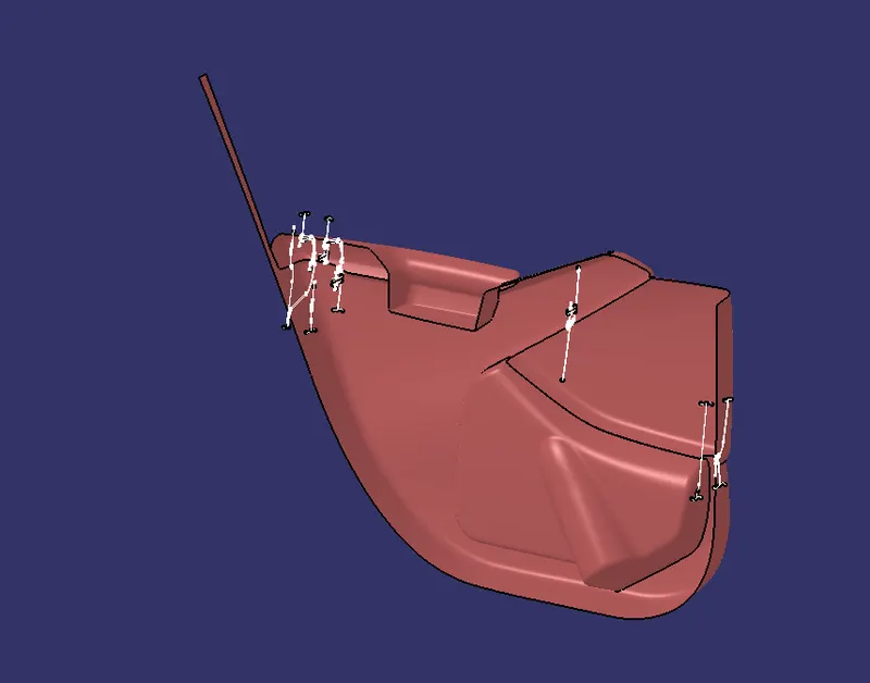
COMPONENTS INCLUDED IN THE DOOR PANEL
- Armrest
- Map Pokect
- Bottle Holder
- Lower Substrate
STEP 1
CLASS A SURFACE CREATION
Class A surfaces are primarily used in the automotive environment and the surfaces have curvature and tangency alignments. Class A surfaces are those aesthetic or free-form surfaces, which are visible to us like interior or exterior, and have an optimal aesthetic shape and high surface quality.For creating those,
- First the reference surfaces were extracted individually and then those surfaces are joined using join feature.
- Check the connectivity by using Boundary Feature.
- Now, select the Shading with Edges without Smooth Edges option and see whether there is any black lines.
- For repairing the dark black lines, use Extract feature and then apply Parallel Curve feature on that extracted lines. And join those parallel curves with drawing lines to close it. After closing it, use join feature on those lines. Now, split those lines form the A surface.
- Now, use Multiple Section Surface feature to fill the surface on the class A surface.
- Finally, join those surfaces with join feature for final look of the class A surface.
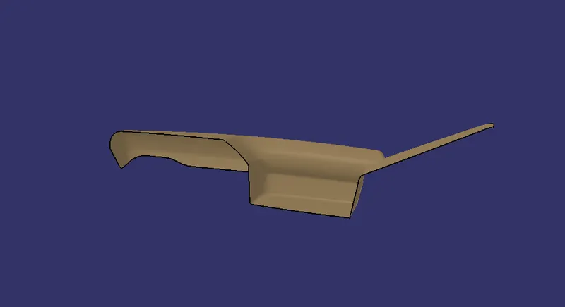
Final class A surface of Armrest
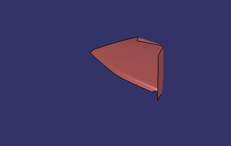
Final class A surface of Map Pocket
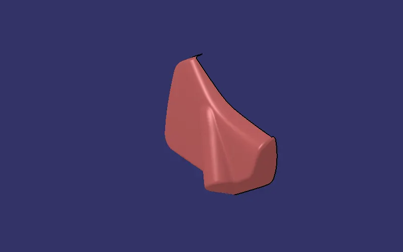
Final class A surface of Bottle Holder
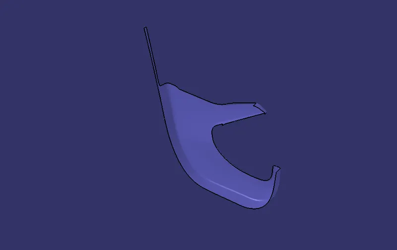
Final class A surface of Lower Substrate.
STEP 2
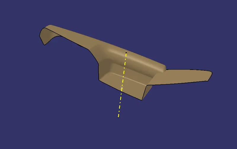
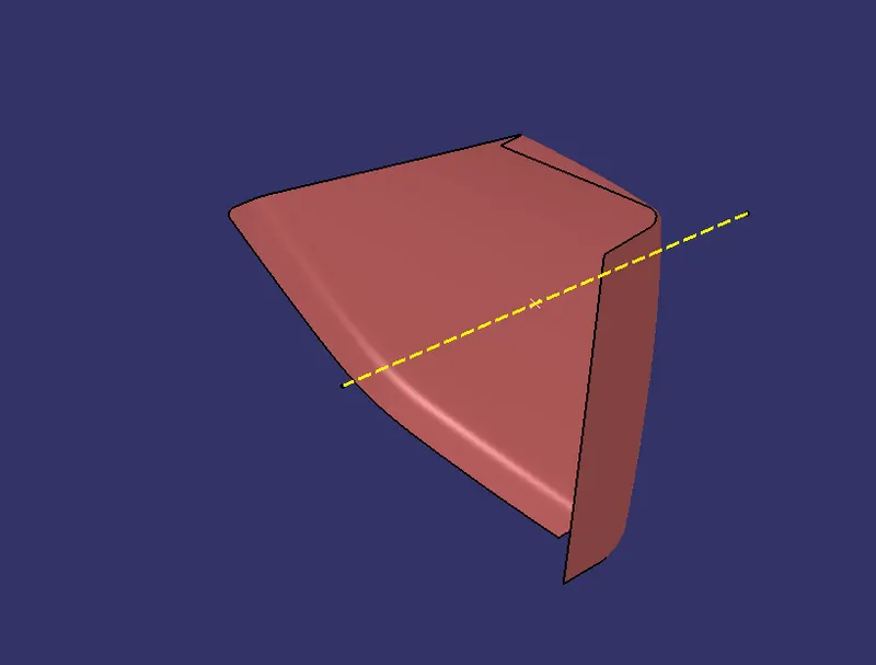
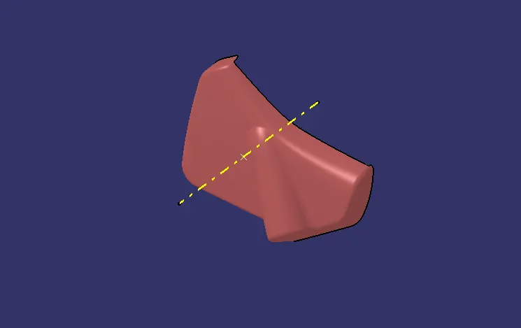
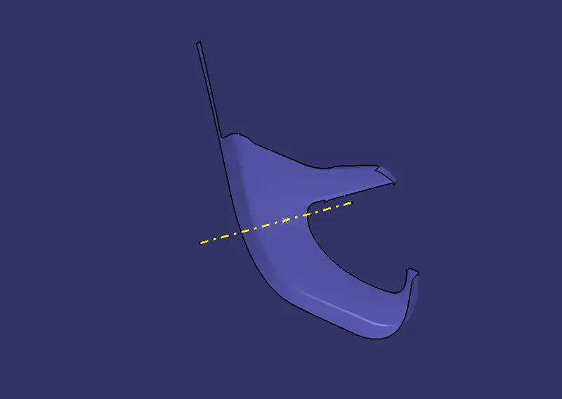
CREATING TOOLING AXIS
The tooling direction is used to find the direction in which the part is removed from the core and cavity. The draft angle for the tooling axis should be positive to manufacture the component without any difficulties.
- First create a point on the flat surface of class A and then followed by a line on that point with respective direction X,Y and Z.
- Or we can create a line using bisecting method with the help of two lines and a point.
Toolig axis for Armrest.
Toolig axis for Map pocket.
Toolig axis for Bottle holder.
Toolig axis for Lower Substrate.
STEP 3
PERFORMING DRAFT ANALYSIS ON CLASS A SURFACE
The draft analysis is used to analyze whether our model is manufacturable based on the draft condition applied.No parts can be ejected from the tool if it is having a straight 90-degree profile from its base surface. A small draft angle is provided to each and every area of the component in order to get easy removal of the component from the tool.The minimum draft value for the Automotive plastic component is 3 degrees.
- To perform draft analysis, use Feature draft analysis.
- There align the compass to the respective tooling axis and lock it.
- Then select the class A surface as the element and click OK to see the analysis
STEP 4
CLASS B SURFACE CREATION
The class B surface is the surface where all the necessary attachments and supports features of the component are made .
- First, offset the class A surface seperately for each surfaces using offset feature.
- Give the offset value of about 2.5 mm refering the given mastersection.
- After offseting, repair work will be their on the offsetted surface, first give edge fillet of about 0.25 mm to those sharp edges to close the repair work if it works or use Multiple Section Surface for filling those surfaces.
- Check for any black line on the surface, if so, extract those line then use Prallel curves feature and split those lines form the surface and agian use Multiple Surface Section feature or Blend feature on those gap to fill.
- Then use join feature to join those surfaes.
- Finally, Extrapolate the surface to extand the surface if necessary.
Offsetted B surface from class A surface for Armrest.
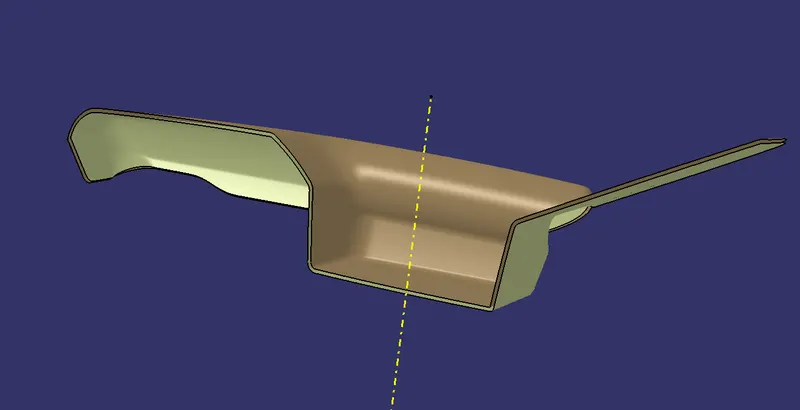
Final class B surface.
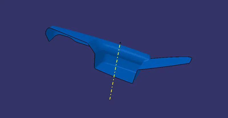
Offsetted B surface from class A surface for Map Pocket.
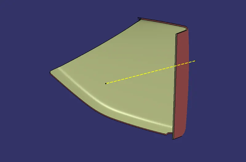
Final class B surface.
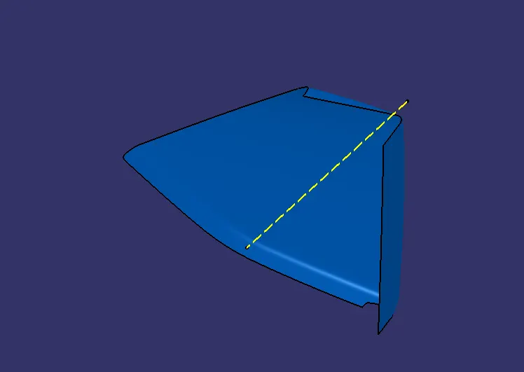
Offsetted B surface from class A surface for Bottle Holder.
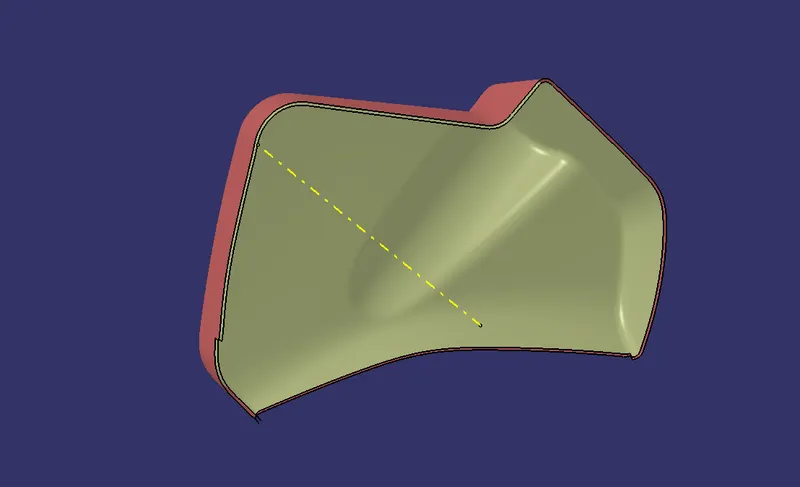
Final class B surface.
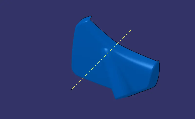
Offsetted B surface from class A surface for Lower Substrate.
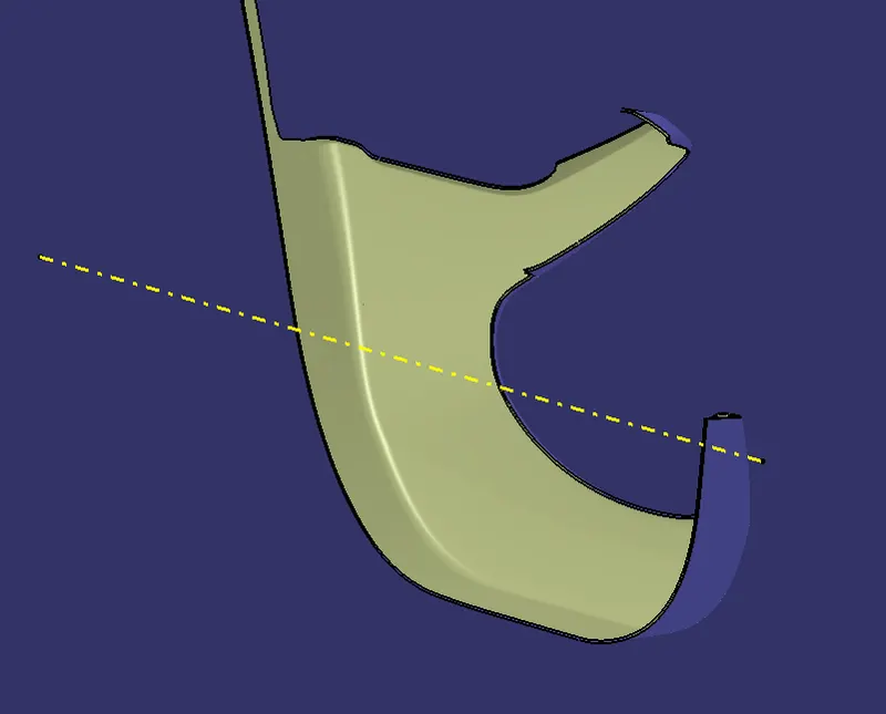
Final class B surface.
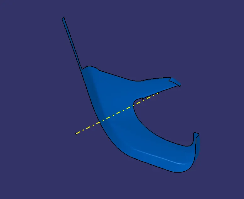
STEP 5
CLASS C SURFACE CREATION
The class C surface are the surface which connects the class A and class B surfaces along the tooling direction. he tooling direction here will be my tooling axis.
- Now, create a boundary on the class A surface individually using Boundary feature. And then use Sweep option to the boundary to create a sweep surface with an draft angle of about 3 or 87 degree respectively. If the sweep came properly without any twist and turns or any sharp edges, then its fine. Otherwise we need to sweep seperately from the class A surface using curve smooth feature and sweep and multiple surface section.
- After doing that, join all the sweeped surfaces using join feature.
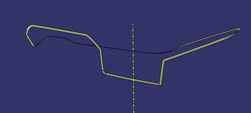
Class C sweeped surface for Armrest.
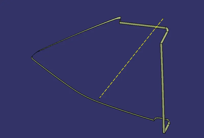
Class C sweeped surface for Map Pocket.
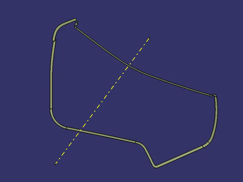
Class C sweeped surface for Bottle Holder.
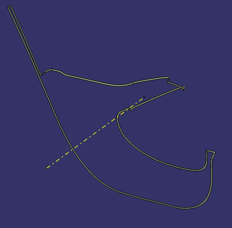
Class C sweeped surface for Lower Substrate.
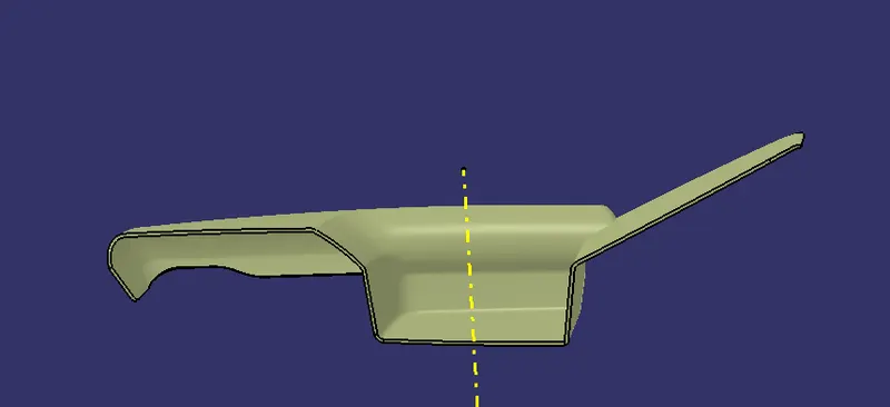
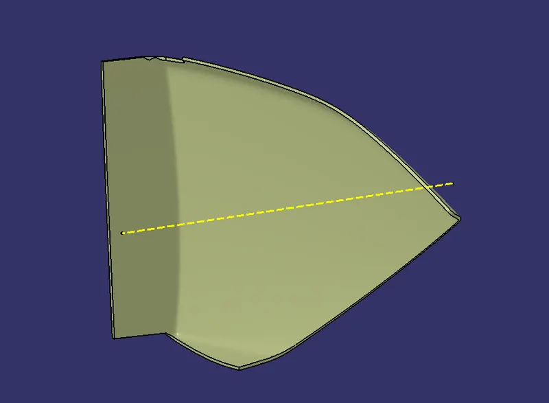
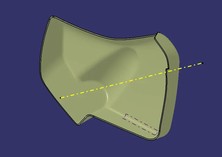
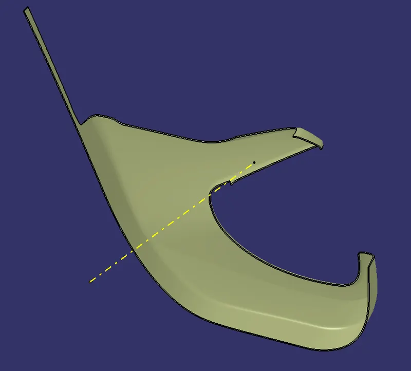
CLOSED SURFACE
- Trim or join the class A surface with the sweeped class C surfaces individually.
- After that, use trim option to trim the class B surfaces with the joined class A and C surfaces to get the closed surface body.
Closed surface of Armrest.
Closed surface of MapPocket.
Closed surface of Bottle Holder.
Closed surface of Lower Substrate.
STEP 6
CREATING B SIDE FEATURES
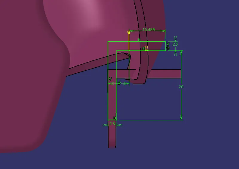
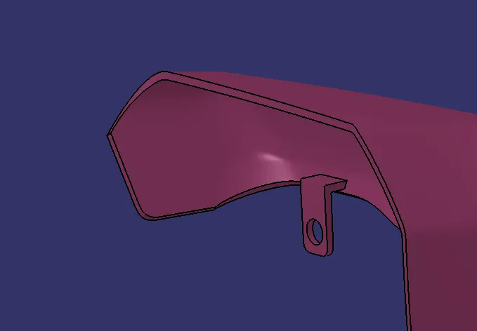
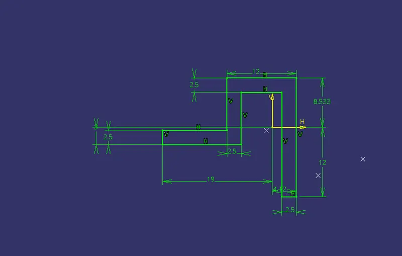
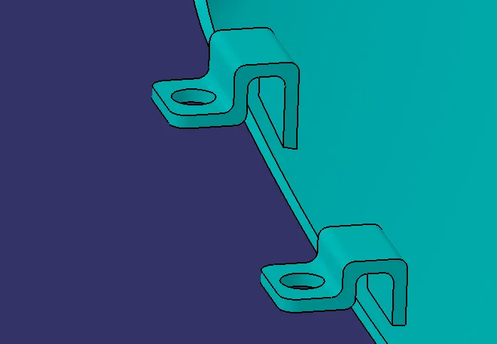
FLANGES
Flanges are the features which is used to join or align the two different components for assembly.
- Flanges of different profiles are drawn to different component according to the orentatioin of that component.
- For the flanges the thickness are given as 2.5 mm.
- The draft angle for the flanges are given as 0.5 degree. Then given fillets to the edges of about 3 mm.
- Then use points, translate and rotation optioins to move flanges to different position as required.
HEAT STACK
Heat stakes also known as thermoplastic staking, it is process of joining two dissimilar materials together.
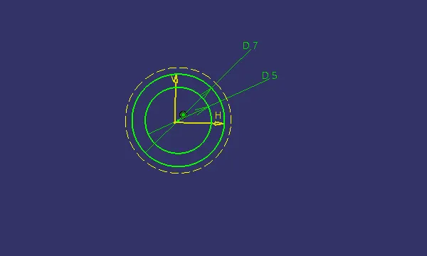
- First create a reference plane on the B surface and draw the profile for heat stack.
- Use Pad option to that sketch and pad it to about 10 to 20 mm as required.
- Now, use draft on the padded surface with an draft angle of about 0.5 degree.
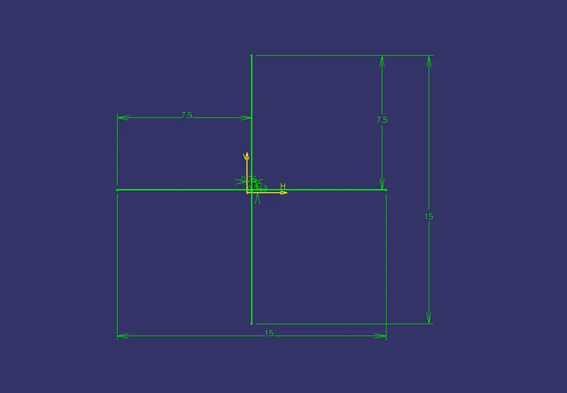
- Then, draw a cross section lines of about 15 mm each for making the ribs for heat stack.
- Again use Pad to the sketch and use draft on it.
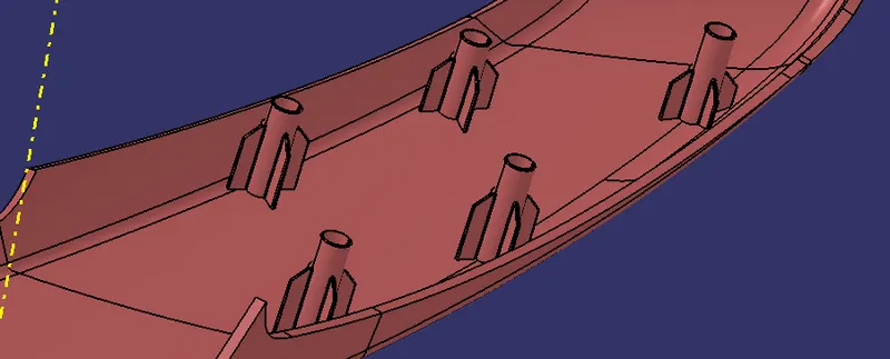
- Then use union trin on the ribs and the heat stack to remove the inner portion.
Sketch profile for heat stack.
Sketch profile for ribs.
Final Heat stack after using union trim with ribs and solid component.
DOG HOUSE
Dog houses are used as supporting features. Sometimes other engineering features like snaps; locators, etc. are mounded on them to increase their strength. They are subjected to draft analysis to prevent breakage of the component during ejection from the mold cavity
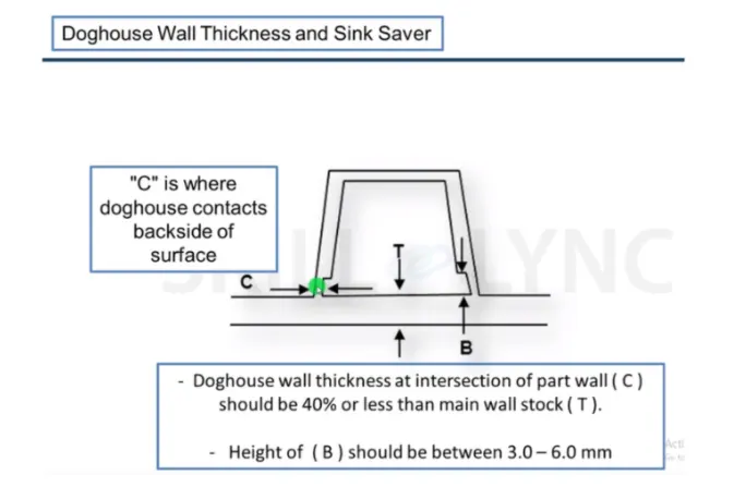
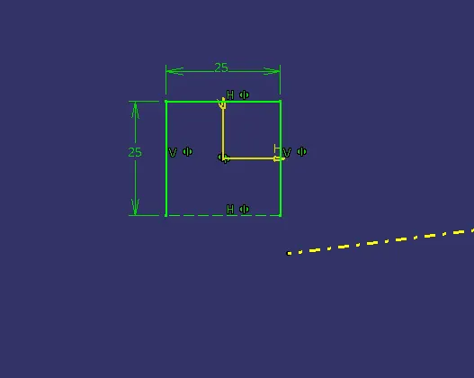
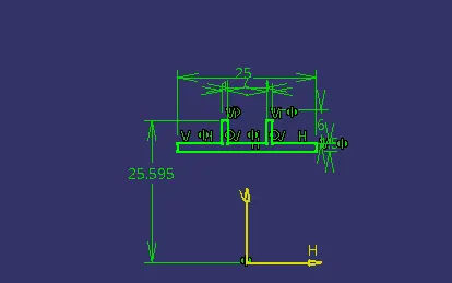
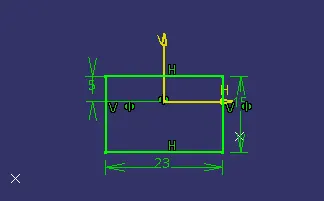
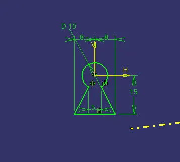
- For creating a dog house on the class B surface, create a plane on the surface using a point and the reference plane or use axis system over there. Then, draw the dog house profile following the given guideline for that. After that use sweep option on that sketch with an given draft angle of about 1.5 degree and use thickness feature in part deign to give thickness to the drafted surface of about 2.5 mm.
- Or extrude that sketch and then pad it to the required height then give draft anlge.
- Again, draw a sketch for creating inside B And C surface for dog house following the guideline and sweep it and give thickness of about 1.8 mm or more.
- Finally, use Union trin feature to trin the two solid component to get the final look of the dog house. Then, use translate and rotate features to align the dog house where ever its required.
Sketches used to craete dog house.
FOUR WAY LOCATORS
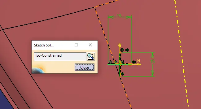
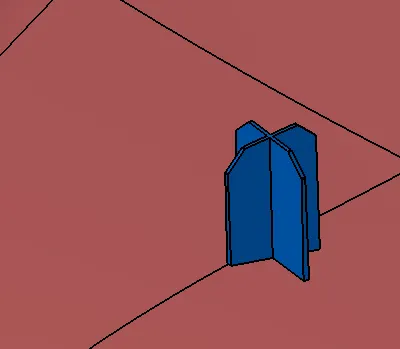
These four way locators are used to locate and restict the degree of freedom of two different components.
- First, create a two lines crossecting each other of about 15 mm each and symmetry it to the axis.
- Use Pad to the sketch of height 20 mm or required height. And use draft on it with an angle of about 0.5 degree.
- And given chamfer of about 3 mm to 45 degree.
PUSH PINS
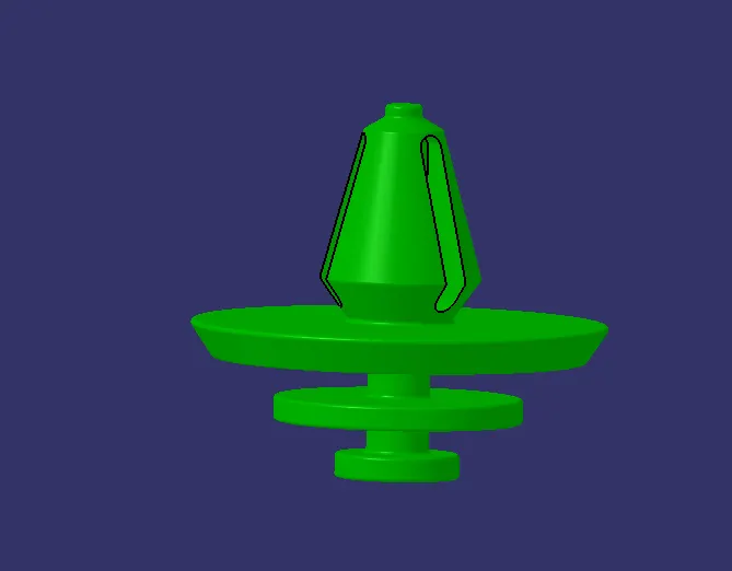
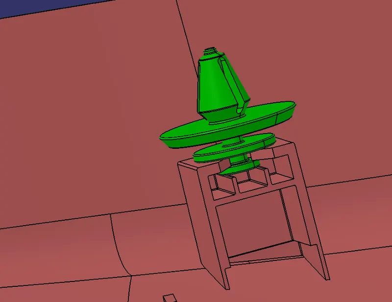
They are used to push the component and act as a fixing element. These are attached to the dog house.
STEP 7
DRFAT ANALYSIS ON FINAL INDIVIDUAL COMPONENTS
ARMREST
MAP POCKET
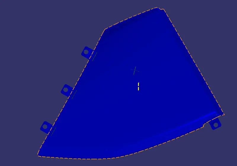
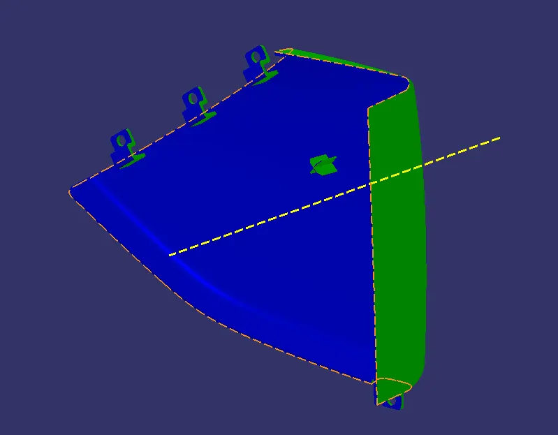
BOTTLE HOLDER
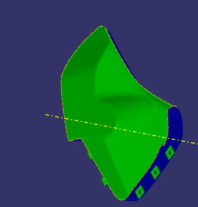
LOWER SUBSTRATE
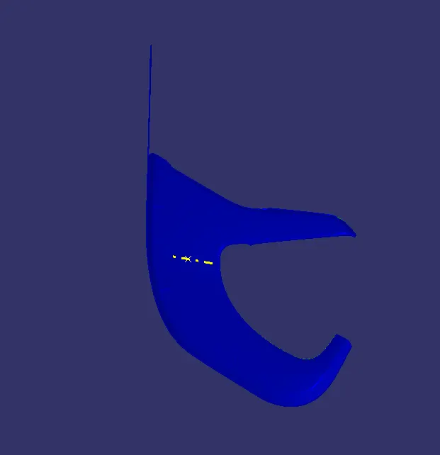
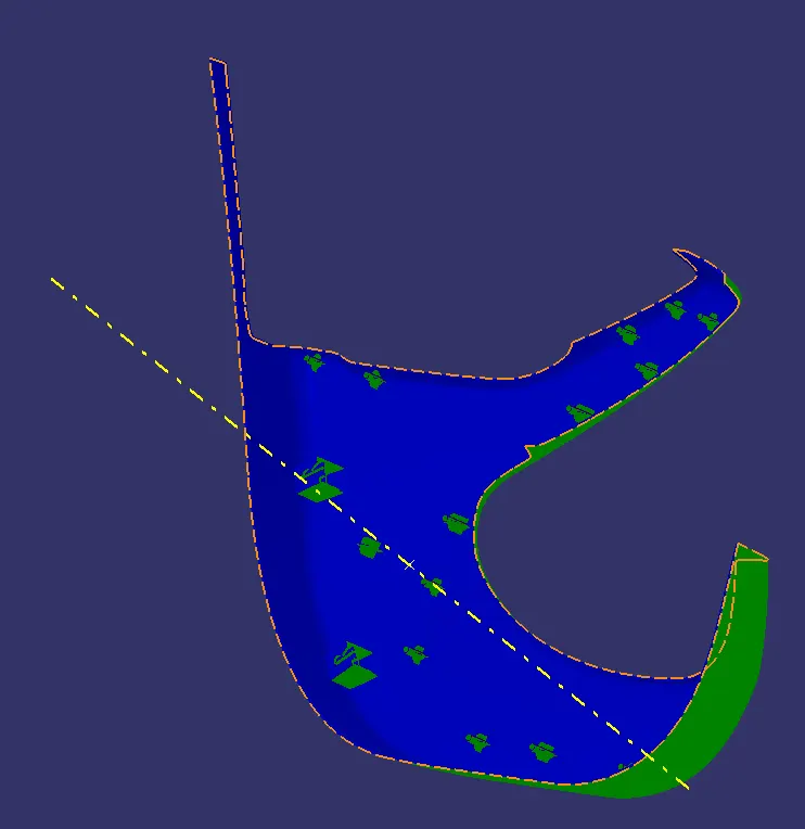
FINAL DRAFT ANALYSIS OF WHOLE COMPONENT
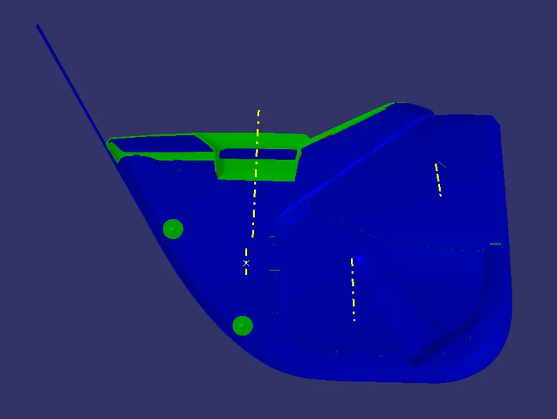
MULTI VIEW OF DRAFT ANALYSIS
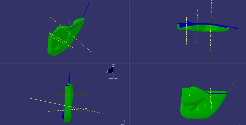
STEP 8
ASSEMBLING OF DIFFERENT PARTS
- For assembling of part we need to fix a component first using constrains toolbar and then use different constrains like Offset, Coincidence and Angle constraints between different parts so that degree of freedom of each parts is zero.
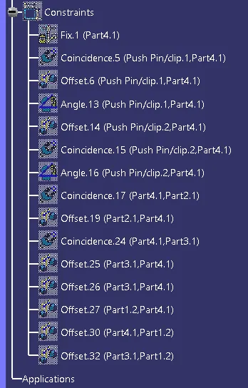
FINAL ASSEMBLED COMPONENT