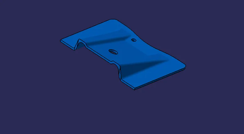
Week 8 - Challenge 1 - Base Bracket Design
AIM :
The objective of this project is to create the Base Bracket Plastic component through the given Class-A surface and for the tooling axis for the given Class-A Surface it should be created, meeting the requirements of the draft angle and also at the end need to perform the Draft analysis on the model.
STEP 1
CREATING CLASS A SURFACE
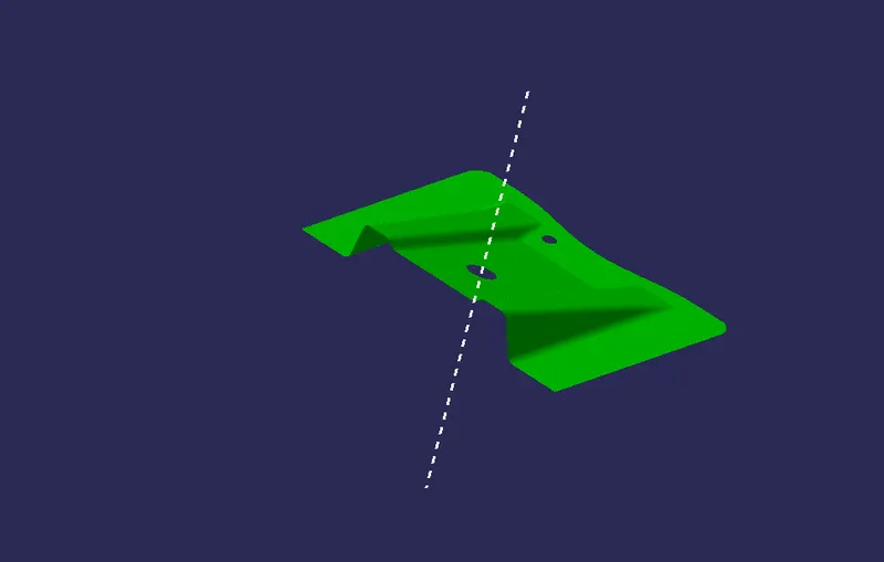
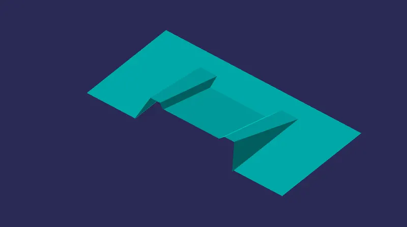
- The below image is the given Class A Surface.
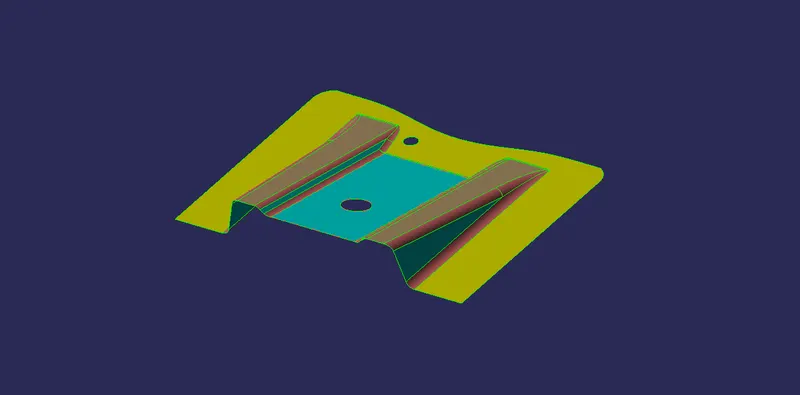
- Check the connectivity of the given Class A Surface by using JOIN or BOUNARY features & ensure that there is no dis-connectivity between any lines.
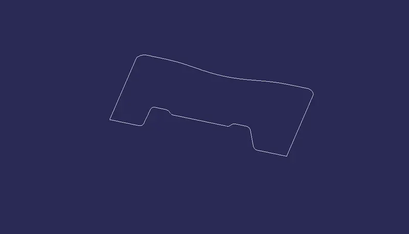
- After checking the connectivity, perform Draft Analysis on Class A Surface.
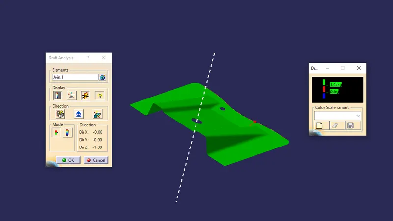
STEP 2
CREATING TOOLING AXIS
- In Z direction there are two holes and has a smooth surface, thus we can determine the tooling axis.There are no surfaces that could cause issues during tooling in this direction when the ZX plane of the axis system is intersected with the input that can be seen.
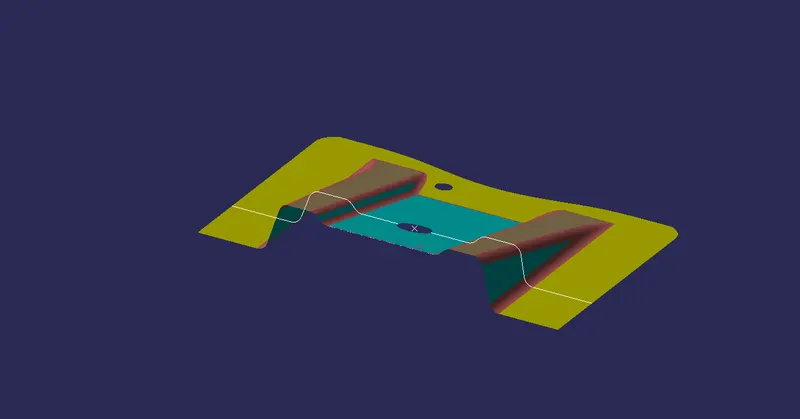
- The nearest parallel surface to assumed drawing direction is chosen for bisecting.
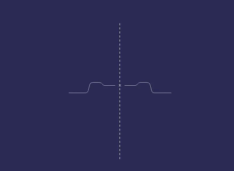
- Two lines are drawn for bisecting.
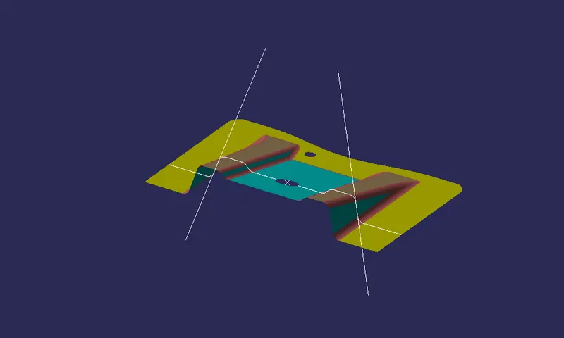
- Tool Axis is created by using the above bisecting lines
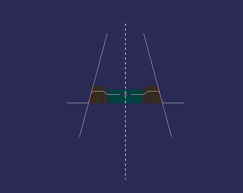
- Thus the TOOLING AXIS is created for Draft Analysis.
STEP 3
CREATING CLASS B SURFACE
- RIB CREATION
- Initally extract the right side rib from Class A surface using extract option .
- Use extrapolate to extend the length.
- Use Un-trim to trim the extracted surface.
- Now, again extrapolate the un-trimmed surface for the final look.
- We need to do tha above process for the other rib creation.
- Finally, Offset the surface to about 2.5 mm below the Class A Surface.
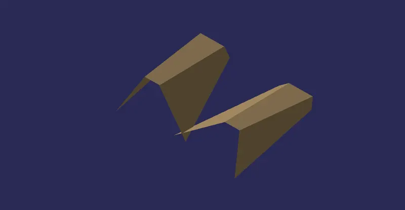
- Offseted Ribs
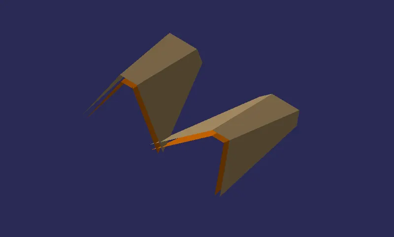
2. CREATING MIDDLE FLAT SURFACE AND BASE SURFACE.
- Again, extract the middle flat connecting surface from class-A. And the use Un-trim on the extracted surface.
- Now, extrapolate the un-trimmed surface.
- Finally, Offset the extrapolated untrimmed surface for about 2.5 mm.
- Now, extract the base surface from class-A surface and Un-trim the base surface and extrapolate the base surface.
- Offset the base surface for 2.5 mm
- Trim the base surface from the middle surface and join all to get the desired Class B Surface.
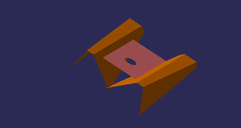
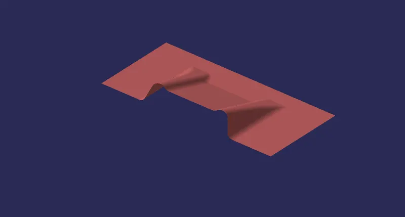
- Class B Surface without fillets.
- Final Class B Surface
STEP 3
CREATING CLASS C SURFACE
- Create a boundary on Class A Surface by using Boundary feature.
- Try to create seperate boundaries from Class A Surface ( ie., outer edges and two different holes)
- Then use Sweep line with draft direction.
- Use this boundary as Guide curve and tool axis as Draft direction.
- Add an angle to about 3 degree to the draft.
- Use Sweep seperately for each boundaries .
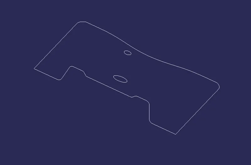
- Class C Surface obtained seperately for different boundaries.
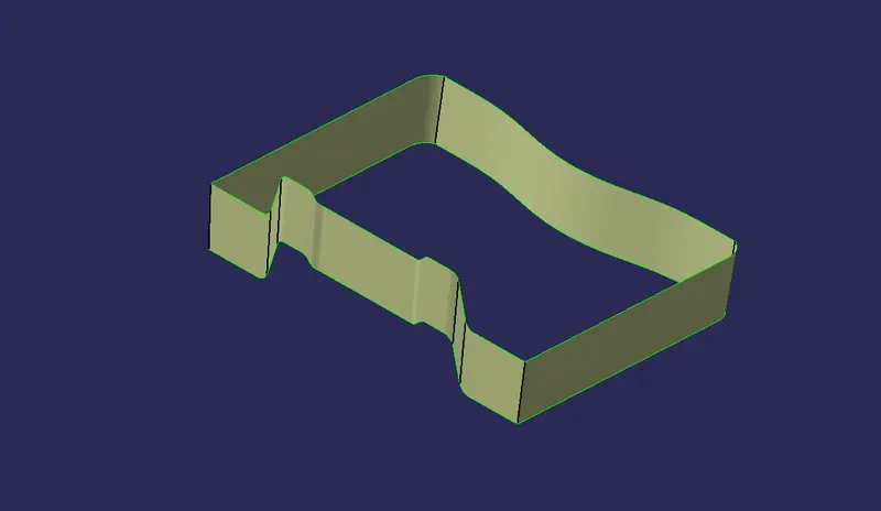
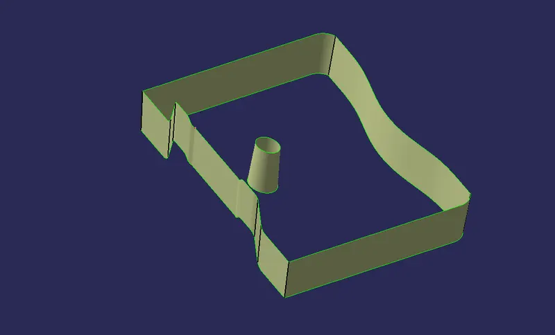
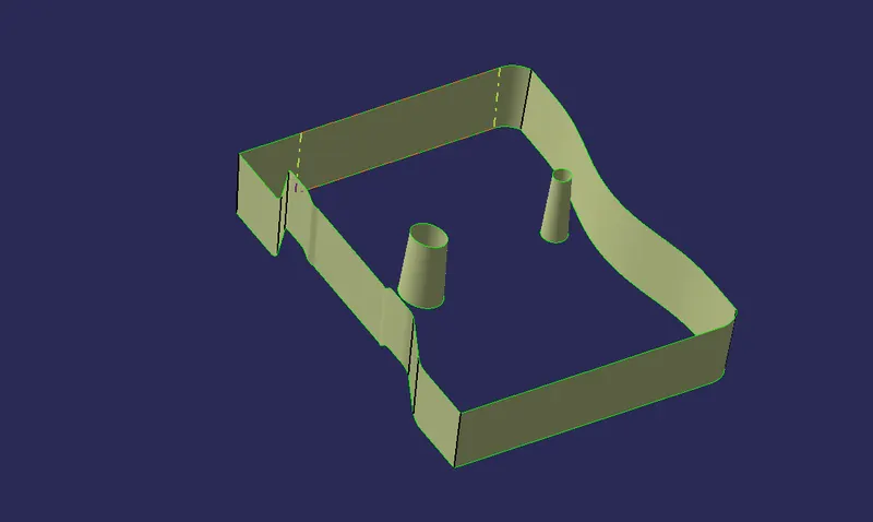
- Now trim the Class C Surface with Class A Surface by using Trim feature.
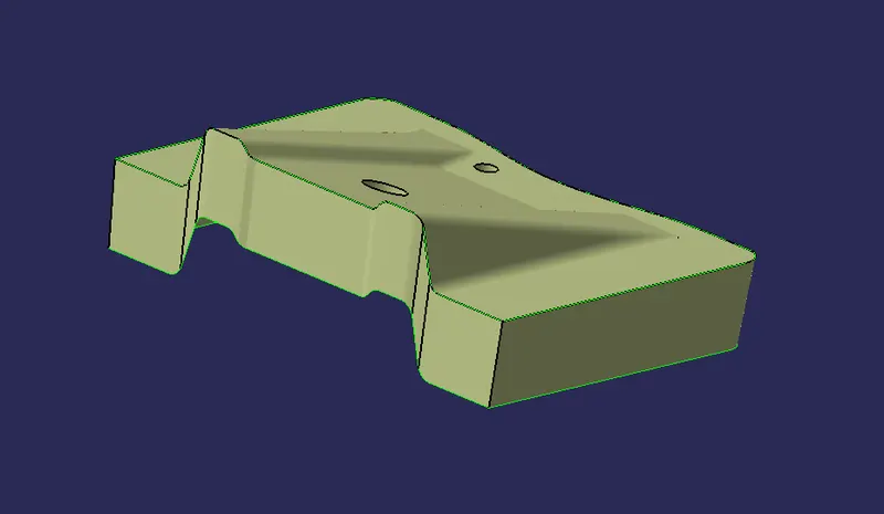
- Finally, Use Trim Feature to trim Class B Surface With Class A and C Trimed Surfaces.
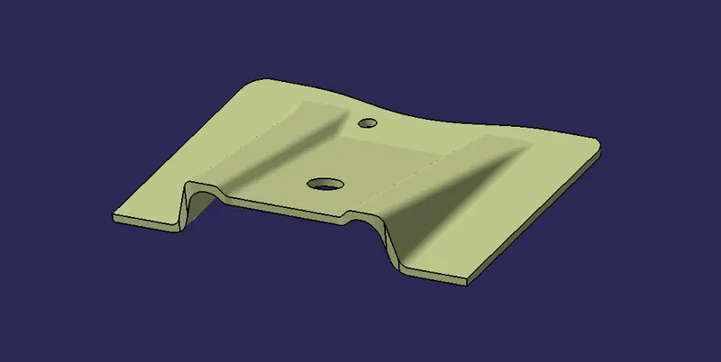
STEP 4
PERFORMING DRAFT ANALYSIS
- For doing Draft analysis the closed surface should on Shading with Material.
- Use the compass to adjust with the tooling direction for pulling out.
- Now, select the Final Trim for the element to draft analysis.
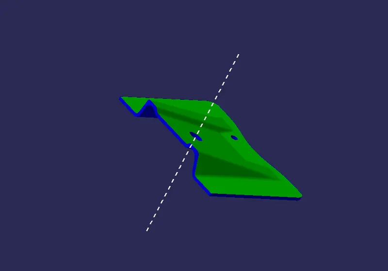
- Finally, the colour scale variants will appear on the closed surface.
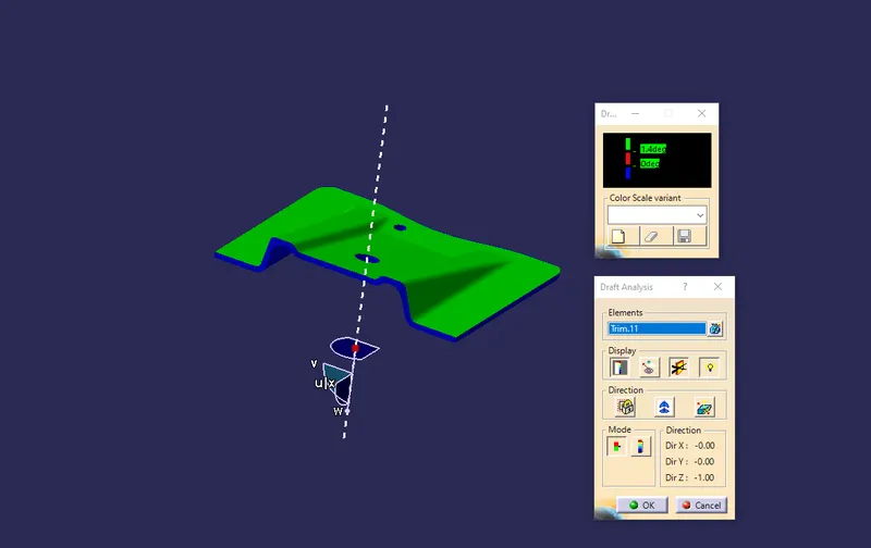
- Final look of Draft Analysis with correct colour variant.
STEP 5
CREATION OF PARTING LINE
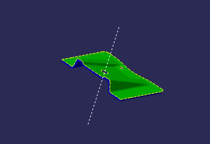
- The parting line is used to showcase the boundary or area where the core and cavity seperates when pulling out.
- Use Multiple Extract Freture to define the boundaries from the Closed Surface.
- After extracting, change the line style to differentiate the parting line.
- The yellow dotted line represents the parting line.
- Multi View
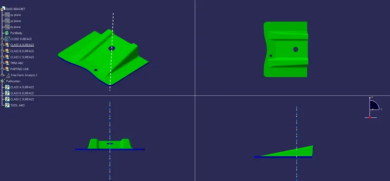
- Solid Closed Component