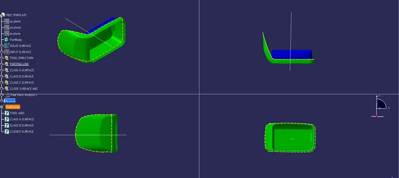
Week 8 - Challenge 3 - Coin Holder Design
AIM : The objective of this project is to create the Coin Holder Plastic component through the given Class-A surface and to begin with, the tooling axis for the given Class-A Surface should be created meeting the requirements of the draft angle and at the end need to perform the Draft analysis on the final closed model.
STEP 1
CREATING CLASS A SURFACE
- Open the STEP File in the software. And then copy the model into the Class A Tree Structure.
- After that, check the connectivity of the surface, if its not connected use JOIN feature to connect all surfaces into single surface.
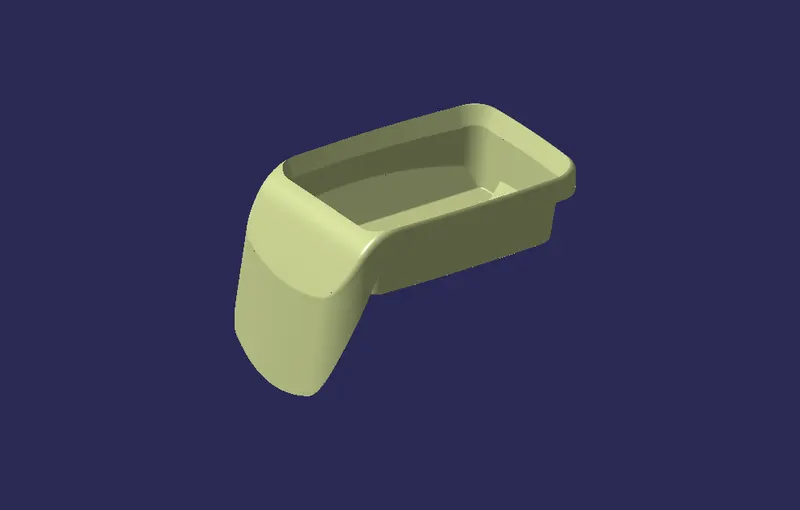

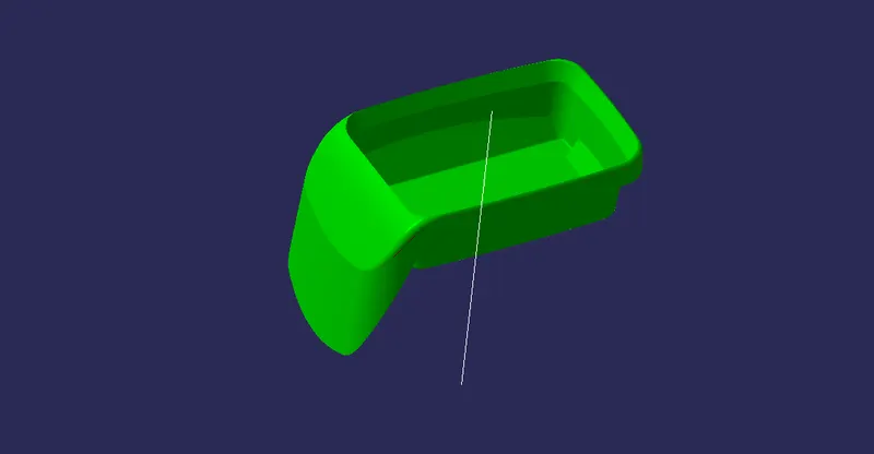
- Class A Surface After using Join feature.
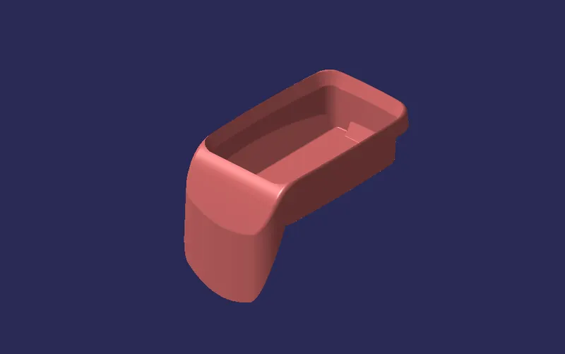
STEP 2
CREATING TOOLING AXIS
- For creating tooling axis, there should be a point on the surface. For creating a point, extract the base surface from class A surface and create a point on that surface. After that, create a line using line type as point and direction.
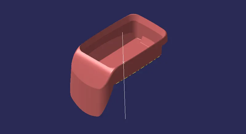
STEP 3
PERFORM DRAFT ANALYSIS ON CLASS A SURFACE
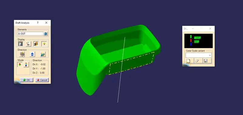
- After creating a Line for Tooling direction perform Draft analysis on the class A surface
- Fot that align the compass with respect to the tooling direction and lock position.
- Select Class A Surface as the element to see the draft analysis.
STEP 4
CREATING CLASS B SURFACE
- After performing draft analysis, copy the Class A Surface and paste it in the Input of the Class B Surface and then hide the class A Surface.
1. SIDE WALL
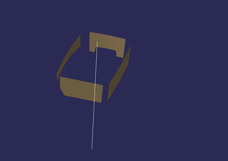
- For creating the side wall of the B surface, extract the side walls from class A Surface by using Multiple Extract feature.
- After extracting the surfaces use Extrapolate feature to expand the surface
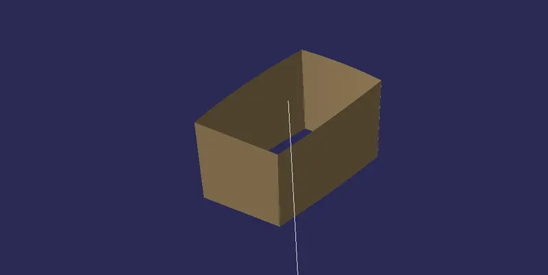
- Use Trim option to join all the surfaces.
- Finally, offset the trimed surfaces to 2.5 mm.
- Then, use Measure between feature to measure the radius of the fillet on class A surface. Use this radius to give fillet to the side wall by using Edge Fillet feature.
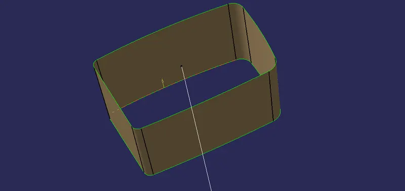
2. BASE COVER
- For base cover, extract the base surfaces from class A Surface.
- And then use Extrapolate feature to expand.
- After doing that, use Trim to join them into single surface.
- Offset the trimmed surface to about 2.5 mm.
- After, offseting trim the base cover with the side wall.

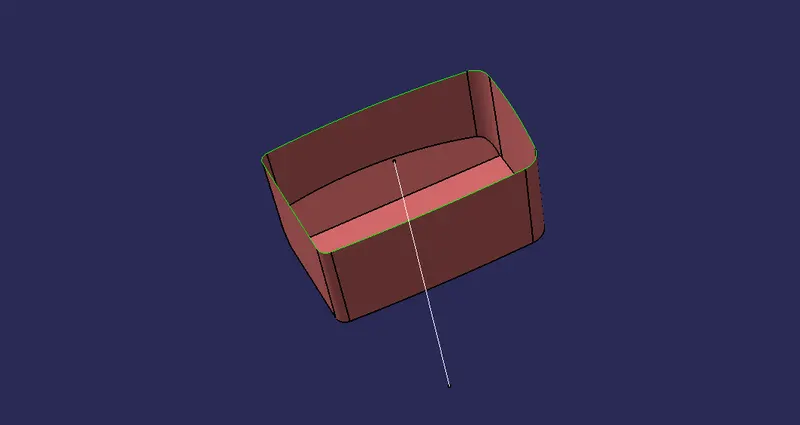
3. TOP WALL
Similarly perform all the operations which was used above.
- Extract the top surfaces form class A Surface by using Multiple Extract feature.
- Join all the suface by using Join feature.
- Then, use Extrapolate to expand the surface.
- Use Offset option to offset the surface to about 2.5 mm.
- Finally, trim the top wall and the base cover.
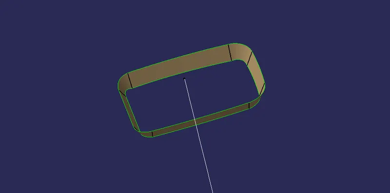
- After Extrapolating the surface.
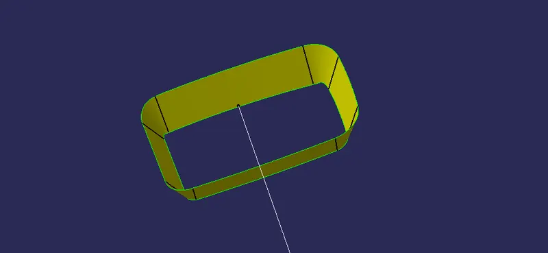
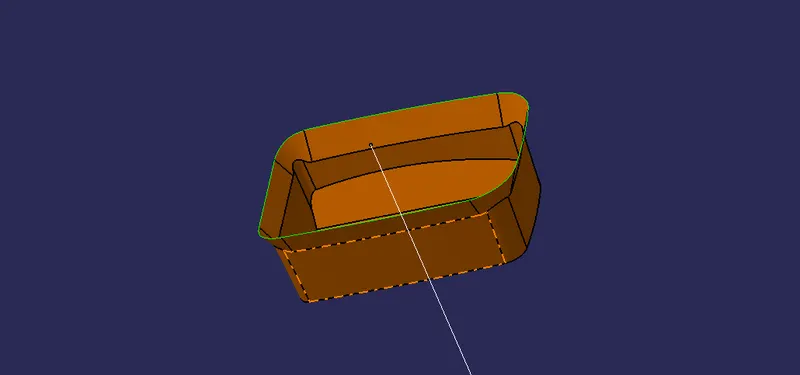
4. OUTER FLANGE
- Extract the outer flange surfaces form class A Surface by using Multiple Extract feature.
- Join all the suface by using Join feature.
- Then, use Extrapolate to expand the surface.
- Use Offset option to offset the surface to about 2.5 mm.
- Trim the outer flange surfaces.
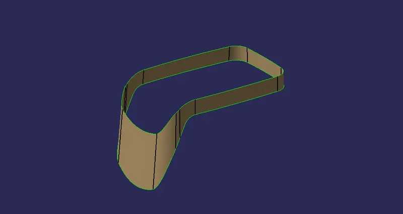
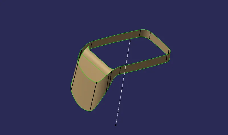
- Finla look of the trimmed surfaceof outer flange.
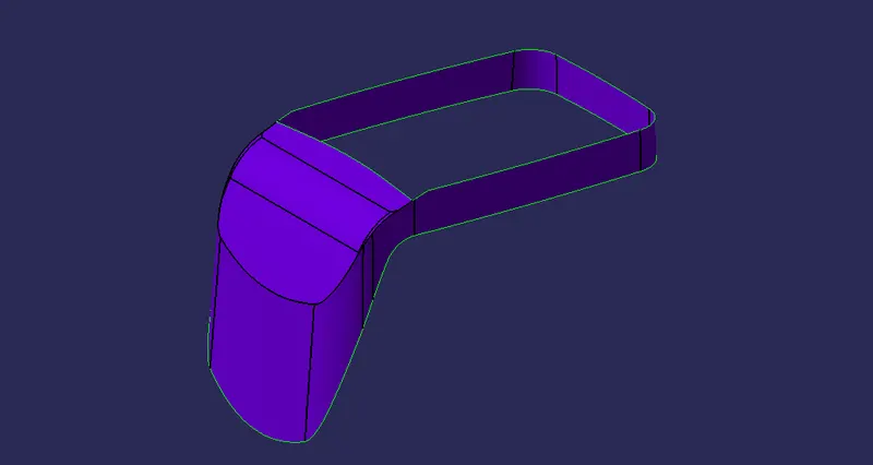
5. INNER SURFACE
- Same way Extract the surfaces on the Class A Surface.
- Then use Untrim the surfaces and the use Extrapolate to expand the surfaces.
- Use Trim feature to trim all the surfaces and Offset them to about 2.5 mm.
- Finally, Trim the surface with the trimmed surfaces.
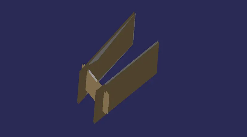
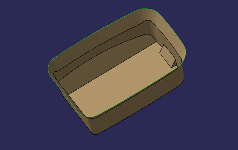
Final Class B Surface
- Trim all the individual surfaces to create Class B Surface.
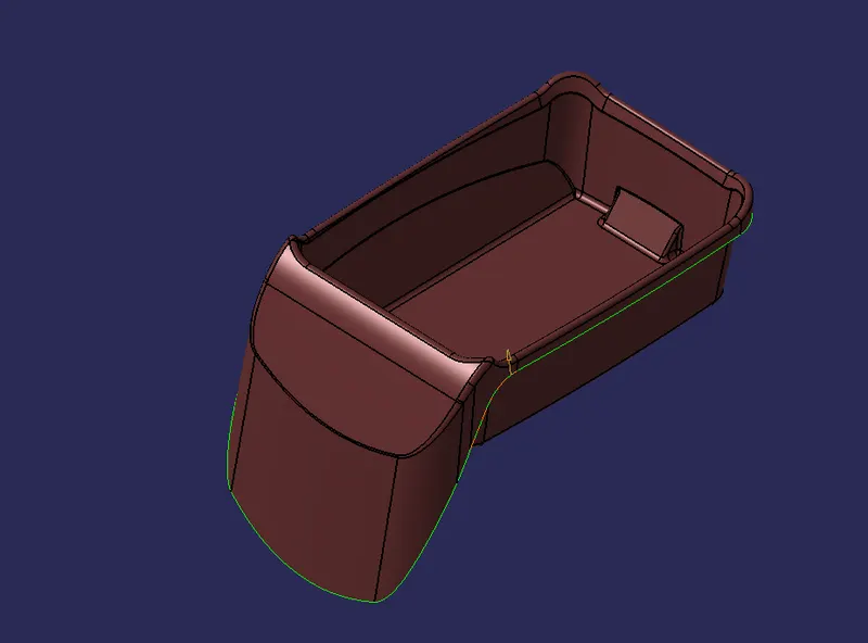
STEP 5
CREATING CLASS C SURFACE
- Create a curve smooth on Class A Surface by by using Curve smooth feature on operation toolbar.
- After that, use Sweep option with line direction. For that, select the curve smooth for guide path and tool axis for draft directiion.
- Add an angle to about 90 degree and for lengt give 5-10 mm. And click preview and ok.
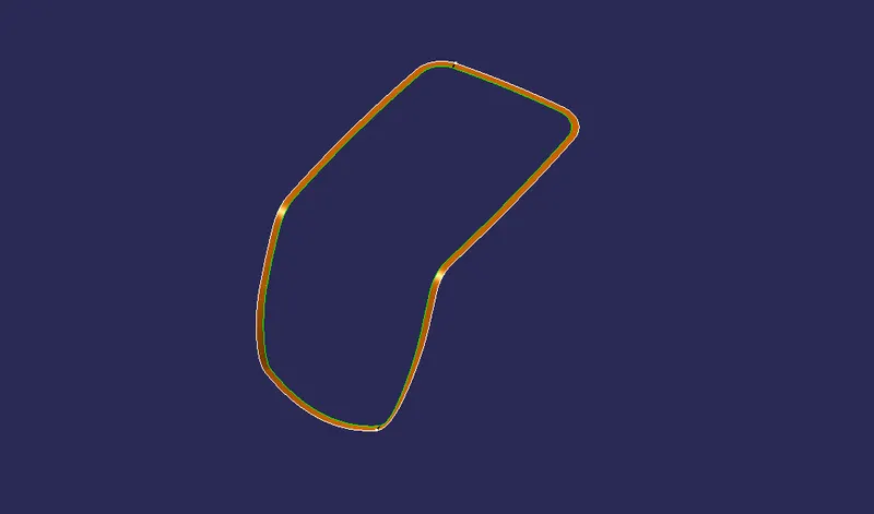
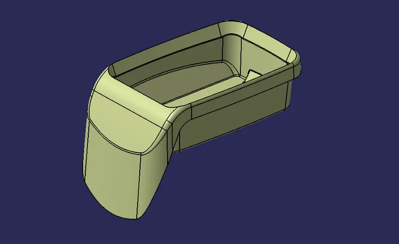
- Now trim the Class A Surface with the Class C Sweeped surface.Finally, trim the surface with the Class B Surface to get the Closed Surface.
STEP 6
PERFORM DRAFT ANALYSIS ON CLOSED SURFACE
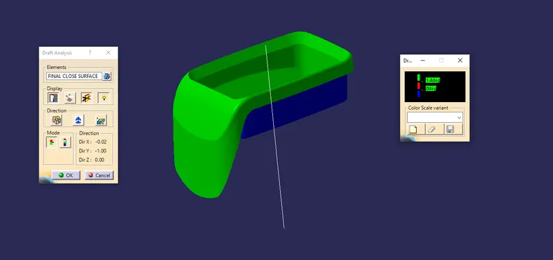
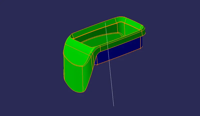
- For doing this analysis, the close surface should be on shading with material mode.
- Select draft analysis and adjust the compass to align with the tool axis and lock the compass.
- Select the closed surface as the element to see ths analysis.
STEP 7
CREATING PARTING LINE
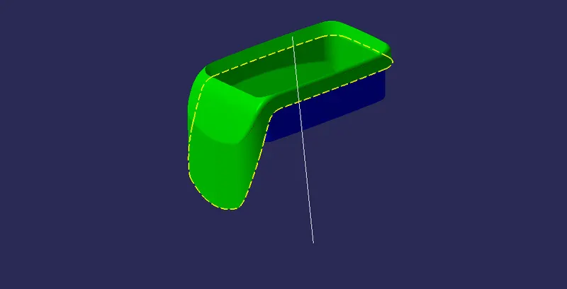
- Use Multiple Extract Feature to define the boundaries from the Closed Surface.
- After extracting, change the line style to differentiate the parting line.
- The yellow dotted line represents the parting line.
STEP 8
SOLID MODEL
- For creating solid model, go to part design and select close surface option and select the closed surface to become solid component.
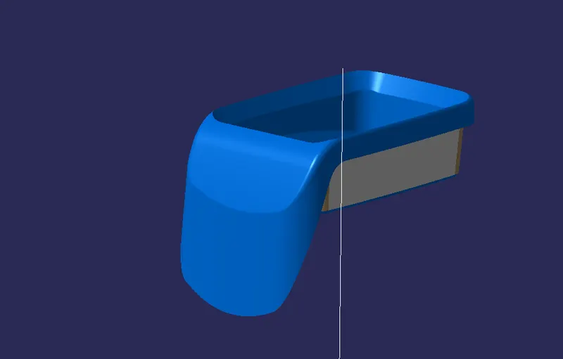
MULTI VIEW