Week 10 - Challenge 1- Attachment Feature Creation (Ribs & Screw Boss)
AIM: The objective of this project is
- To create the Door Handle closed component from the given Class-A surface.
- To create the tooling axis for the given Class-A Surface meeting the requirements of the draft angle.
- To create the Ribs and Screw Boss on the B side surface considering the design rules for that.
- To perform the Draft analysis on the model
STEP 1
CLASS A SURFACE
- First, open the given class A surface and check the join all the surfaces in class A by using Join feature.
- After that, check the connectivity (ie., boundary check) of that surface by using Boundary featrure. It should create a single outer surface boundary if correct.
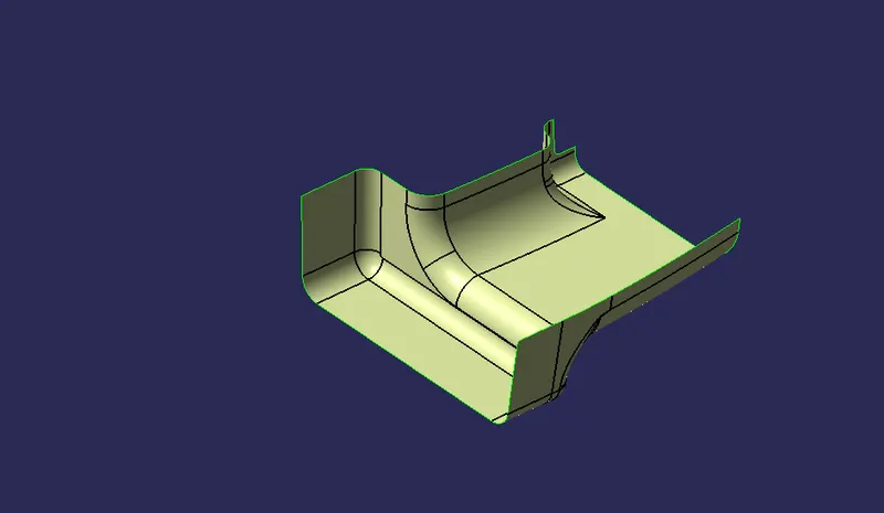
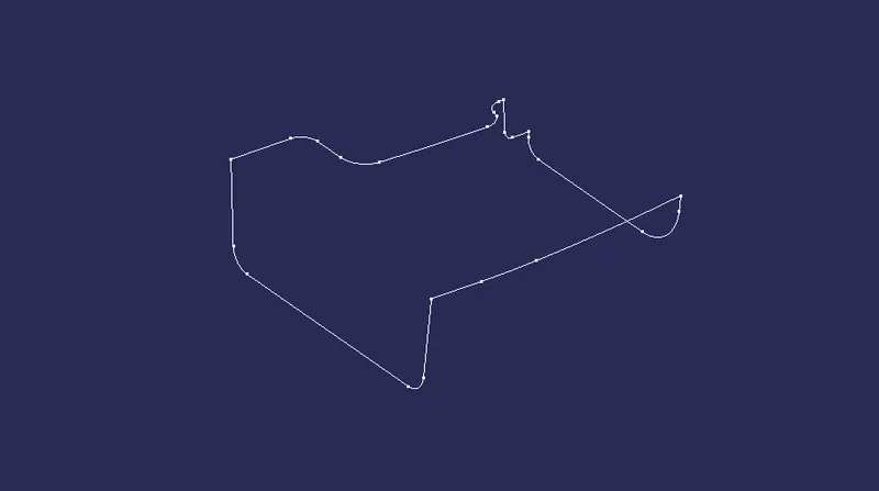
- Final Class A Surface after joining.
STEP 2
TOOLING AXIS
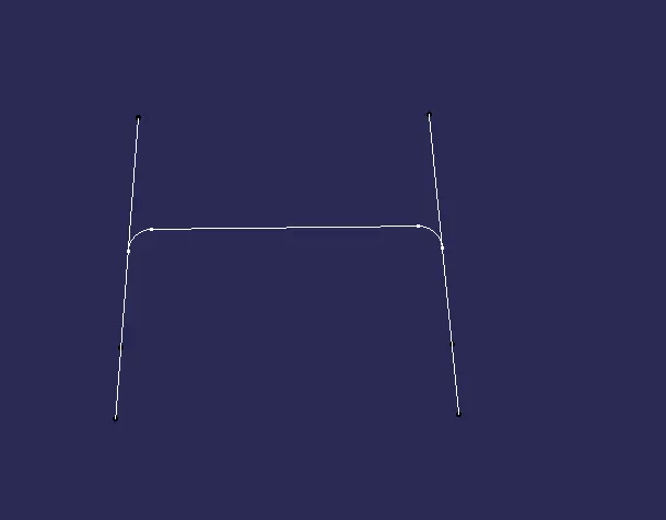
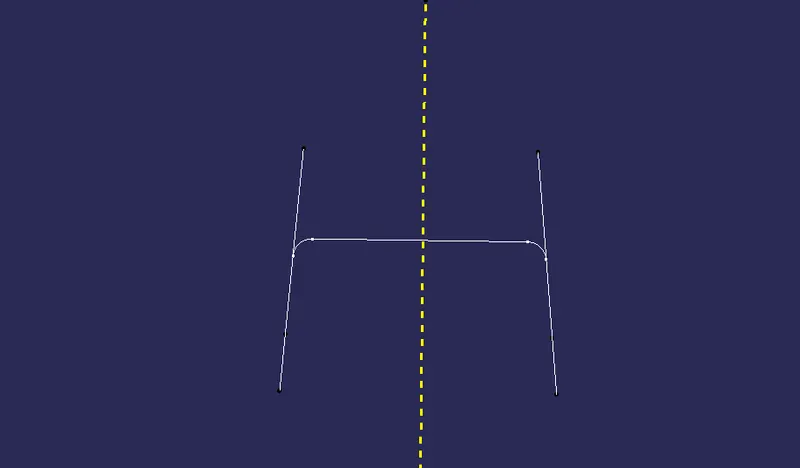
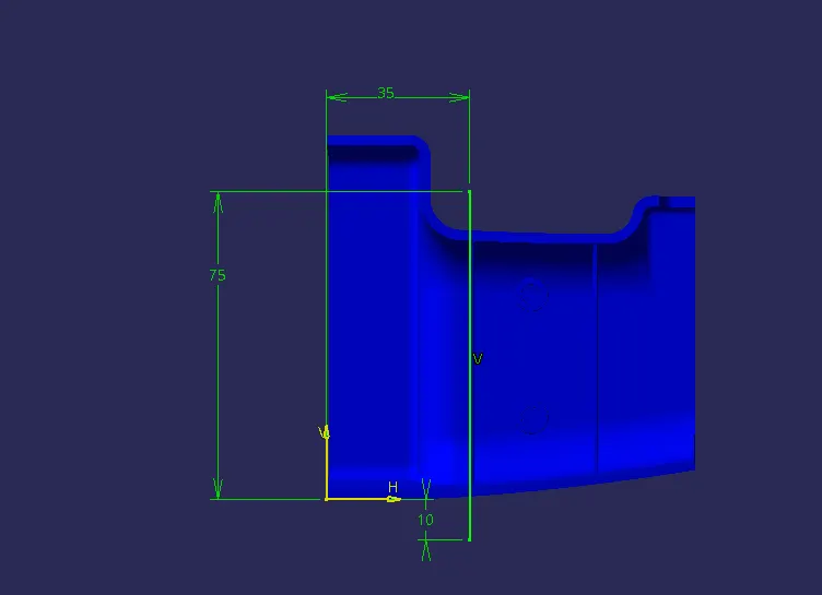
- For tooling axis, create a point on the surface and then create a line with respect to the point and the z direction.
- Then, create a plane on that point and use Intersect and click the surface. After doing that, create two line by using point-point method so that we can bisect the third line using these lines and the point. Thus, the tooling axis is created.
STEP 3
DRAFT ANALYSIS ON CLASS A SURFACE
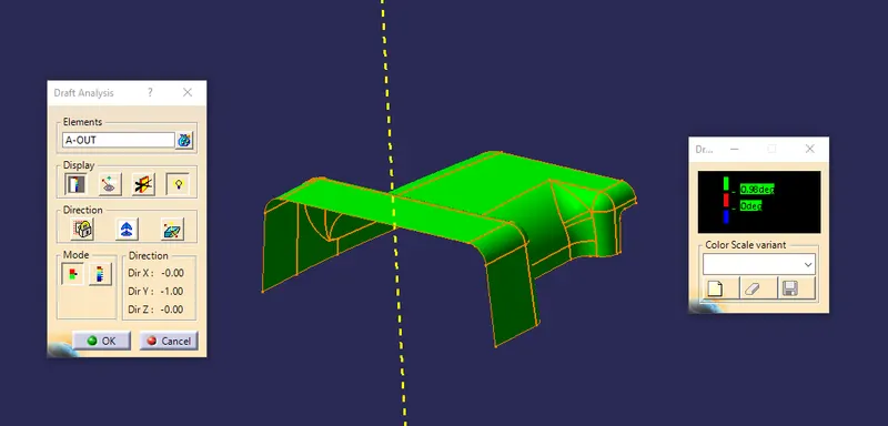
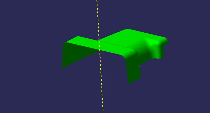
- After creating tooling axis, perform draft analysis using Feature draft analysis. Align the compass to the tooling axis and lock it. Then select the class A surface as the element and click OK.
STEP 4
CLASS B SURFACE
- For creating class B surface, Offset the A surface with a distance of about 2.5 mm using Offset feature.
- Some surface will be removed while doing offset, for that surface use boundary feature to create boudary and use Multiple Section Surface to create the missing surface on class B.
- After creating th surface, join all the surface by using Join feature. Then, use Extrapolate to extend the surface.
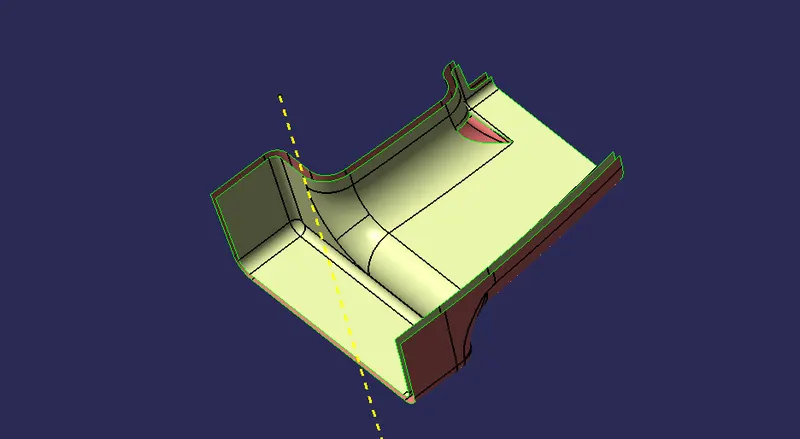
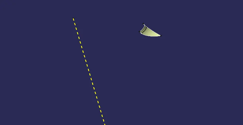
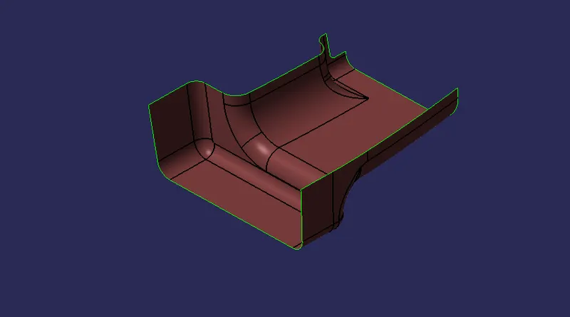
- Final Class B Surface after joining and extrapolating.
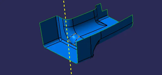
STEP 5
CLASS C SURFACE
- First, create a boundary on class A surface using Boundary feature. Then use Sweep feature for sweeping. If the sweep didnt come properly, then create seperate boundaries and use sweep (with reference surface) for each boundaries.
- After doing that, use Trim feature to trim the Class A Surface with the sweeped surfaces individually.Finally, the Class A and C surafces are trimed and joined.
- Then, finally trim that surface with the class B surface to get the closed component.
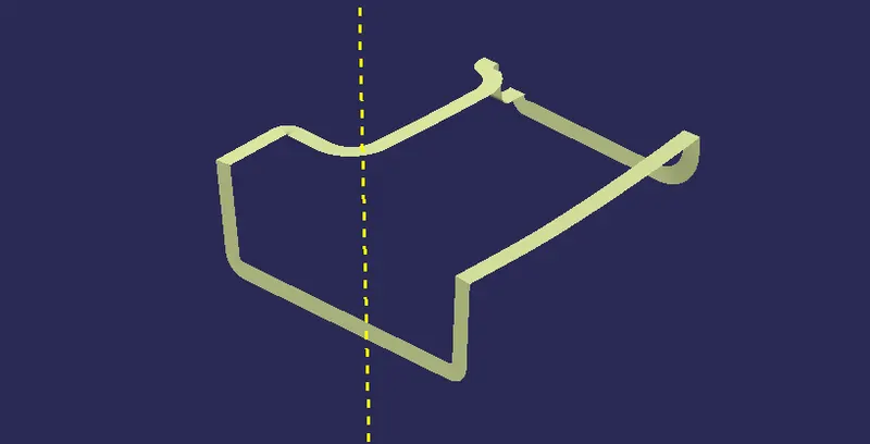
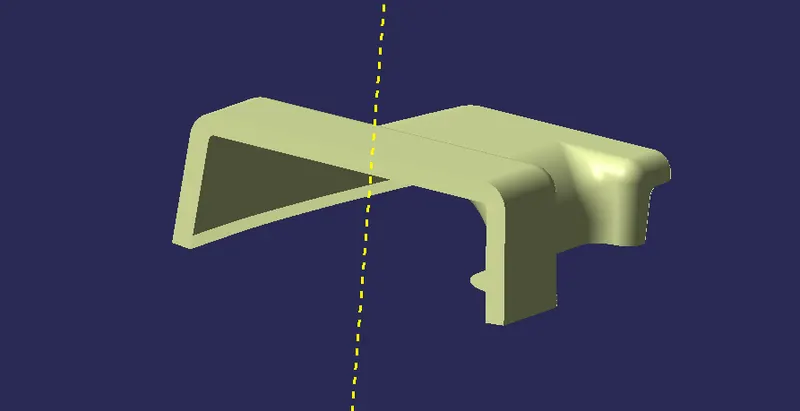
- Final Closed Surface
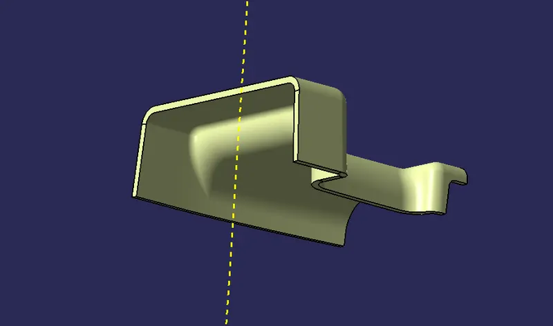
- Draft Analysis on Closed Surface
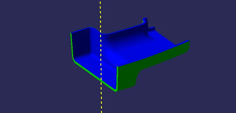
SOLID COMPONENT
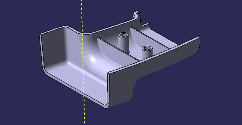
For making it solid, go to part design and use Close surface to make the surace into solid part.
STEP 6
B SIDE FEATURE CREATION
RIBS CREATION
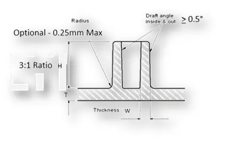
- Design Guideline For Rib Creation
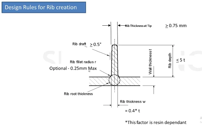
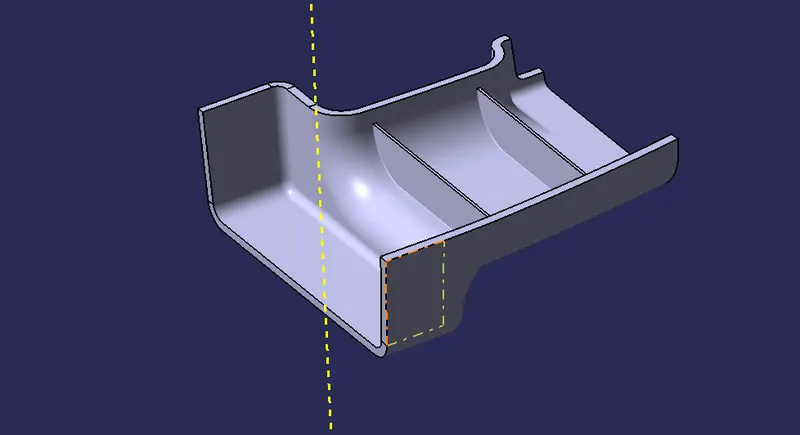
- For creating rib, first create a plane on the B surface and use positioned sketch. Draw a line with required length and use Pad with Thickness about 1 mm .
- After that, use Draft feature to the rib with an draft angle of about 0.5 degree following the guidelines. Then, use Rectangular pattern on the rib.
- Finally use Union Trim on the ribs to remove unnecessary surface.
- Use Edge Fillet feature to give fillets (radius=0.25 mm) to the ribs. Thus, Ribs are created.
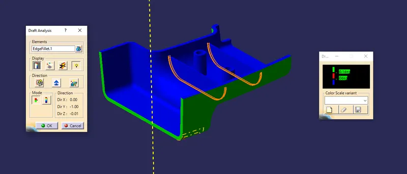
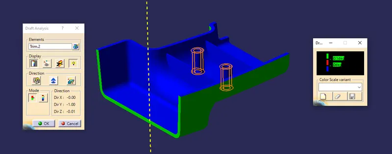
- Perform draft Analysis on the solid component where ribs are created.
SCREW BOSS CREATION
- Design Guidelines For crating Screw Boss
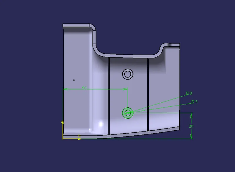
- Use positioned sketch on the plane created on the B surface. Draw 2 circles of diameter 5mm and 8mm with the same orgin.
- Then, use pad to the height of 15mm by following the guideline.
- After that , use draft on the screw boss with an draft angle of 0.5 degree.
- Finally, perform draft analysis on the solid component where screw bossses are created.
RIB ROOT THICKNESS ANALYSIS
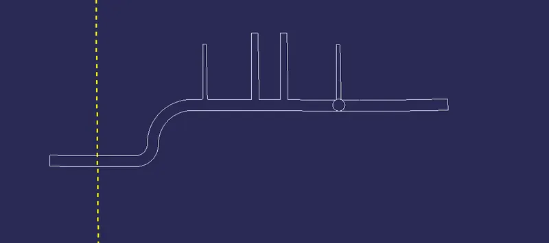
- First, create a plane parallel to the yz plane where it intersect the ribs and the screw boss. After creating the plane, use Intersect feature to showcase the lines of the solid component, the ribs and the screw boss.
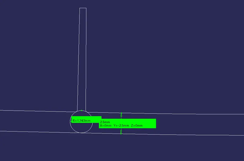
- Extarct the conners of the ribs to draw a circle with tritangent method. Then mesaure the circle to check the dimension.
- Final draft analysis
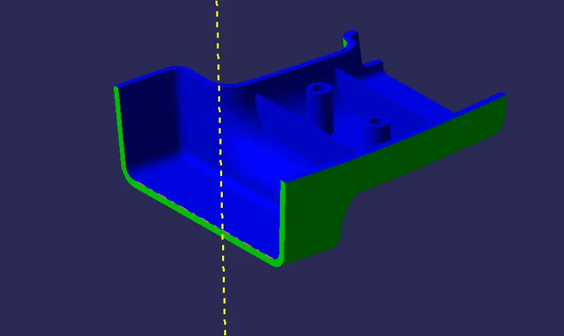
- SOLID COMPONENT
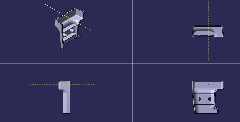
- Multi Section View
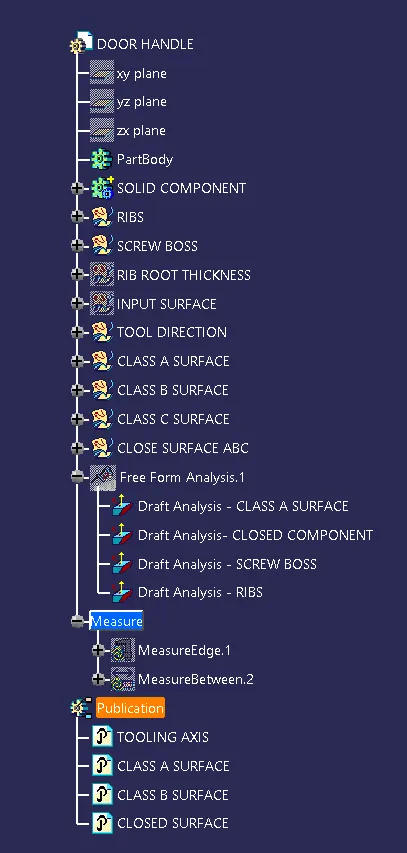
- Tree Structure