Week 8 - Challenge 2 - Switch Bezel Design
AIM: The objective of the project is to create the Switch Bezel Plastic component through the given Class-A surface and the tooling axis for the given Class-A Surface should be created meeting the requirements of the draft angle and at the end need to perform the Draft analysis on the model.
STEP 1
CREATING CLASS A SURFACE
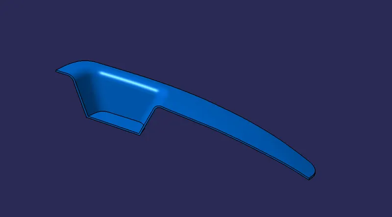
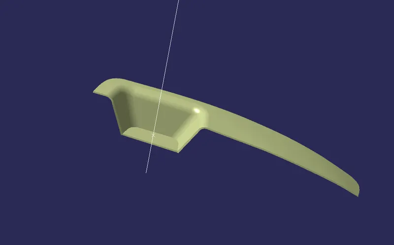
- The below image is the given Class A Surface.
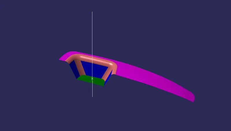
- Check the connectivity of the given Class A Surface by using JOIN or BOUNARY features & ensure that there is no dis-connectivity between any lines.
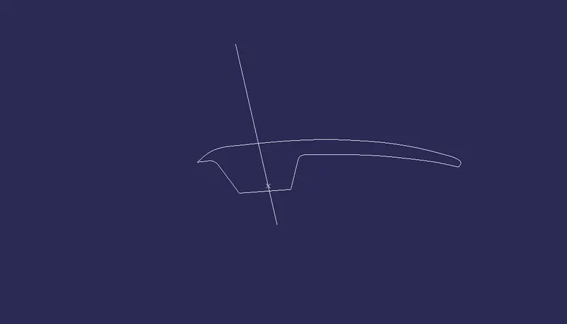
- Class A Surface After using Join feature.
STEP 2
CREATING TOOLING AIXS
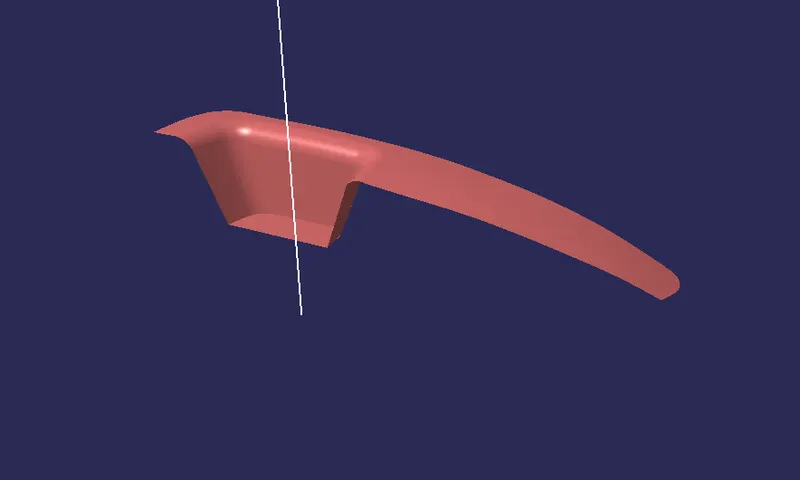
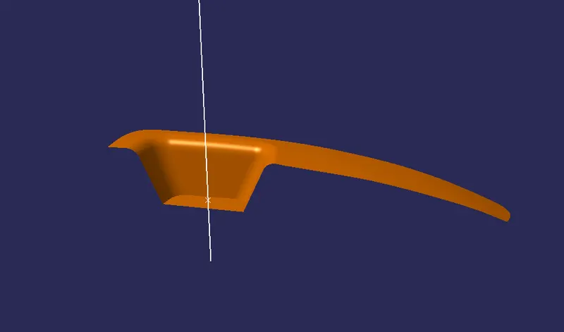
- For creating tooling axis, first create a point on the Class A surface.
- Then, create a line on the surface using line feature with reference to that point and the Z- direction.
STEP 3
PERFORMING DRAFT ANALYSIS ON CLASS A SURFACE
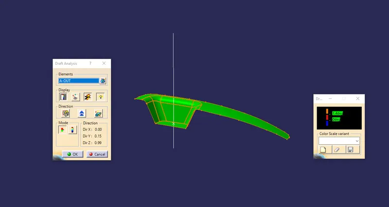
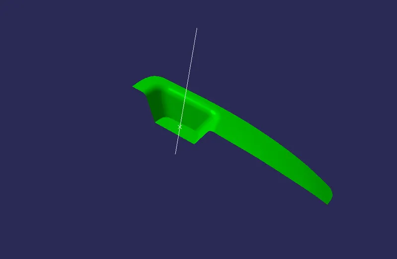
- After checking the connectivity on class A surface, perform Draft Analysis on it.
STEP 4
CREATING CLASS B SURFACE
- To create Class B surface, offset the Class A Surface by using OFFSET feature.
- Give the offset value of about 2.5mm to the reverse direction of Class A Surface.
- After doing offset, check the offseted surface if there is any extra projected surfaces.
- If so, then perform EXTRAPOLATE on the extended surface and trim the unwanted projections using TRIM feature.
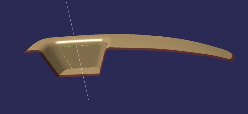
- Final Class B Surface after using extrapolate.
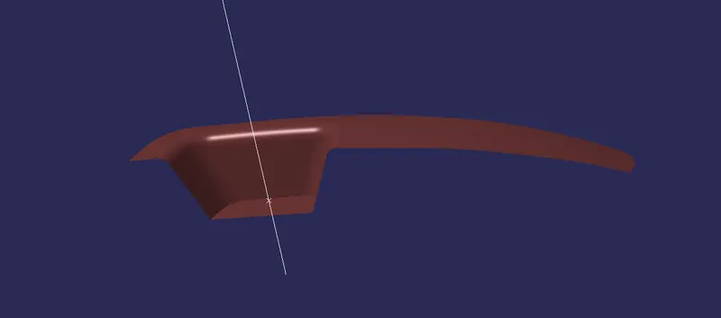
STEP 5
CREATING CLASS C SURFACE
- To create Class C Surface first create a boundary on Class A Surface by using Boundary feature.
- After creating a boundary, check whether its smooth or not. If not, use Curve Smooth feature to make the boundary smooth.
- Then, use Sweep on the boundary created with an draft angle of 3 degree.
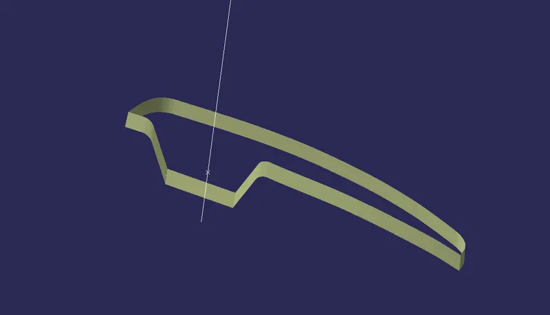
- After creating surface C by using Sweep, trim the Class A Surface with the Sweeped surface.
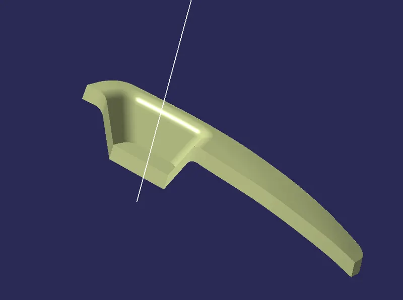
- After triming both surface, again use Trim feature to trim with the Class B Surface to get the closed surface.
STEP 6
PERFORMING DRAFT ANALYSIS ON CLOSED SURFACE
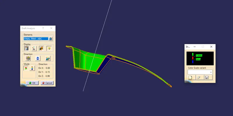
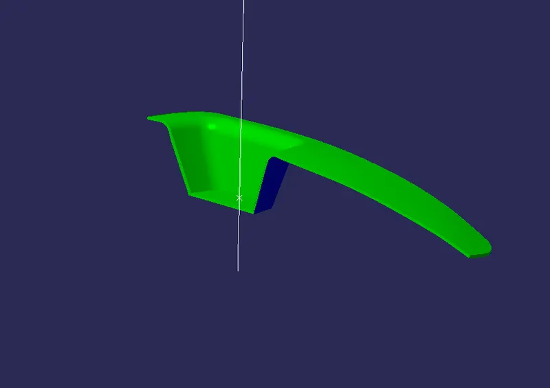
- For doing Draft analysis the closed surfac, the surface should on Shading with Material.
- Ckeck the compass to align with the tooling axis direction.
- If, it becomes red adjust the compass accordingly to get the positive draft.
STEP 7
CREATING A PARTING LINE
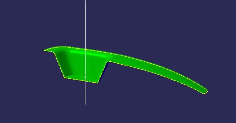
- The parting line is used to showcase the boundary or area where the core and cavity seperates when pulling out.
- Use Multiple Extract Freture to define the boundaries from the Closed Surface.
- After extracting, change the line style to differentiate the parting line.
- The yellow dotted line represents the parting line.
- Multi view
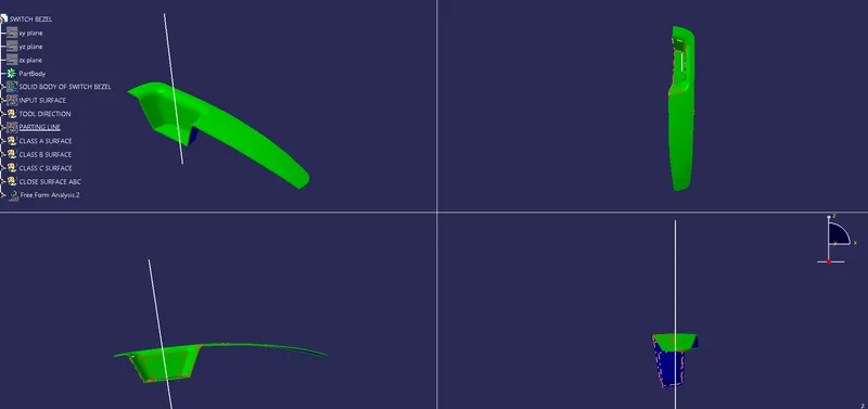
- Solid Closed Surface