Week 10- Assembly Workbench
AIM: The objective of this project is to create all the parts in the given drawing sheets and assemble them in assembly workbench with their respective working position by maintaining proper orentiation and resticting the degree of freedom using assembly workbench constraints.
QUICK RETURN MECHANISM
STEP 1
PART MODEL CREATION
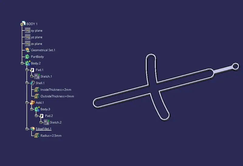
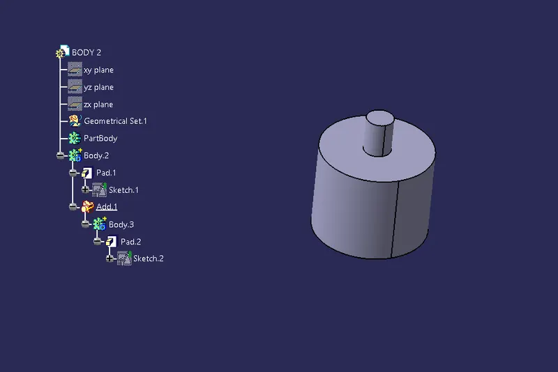
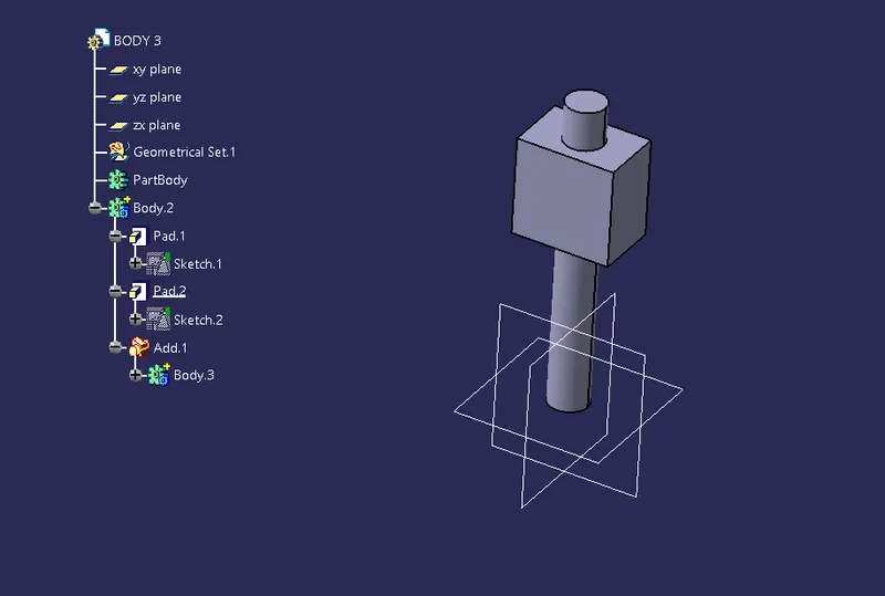
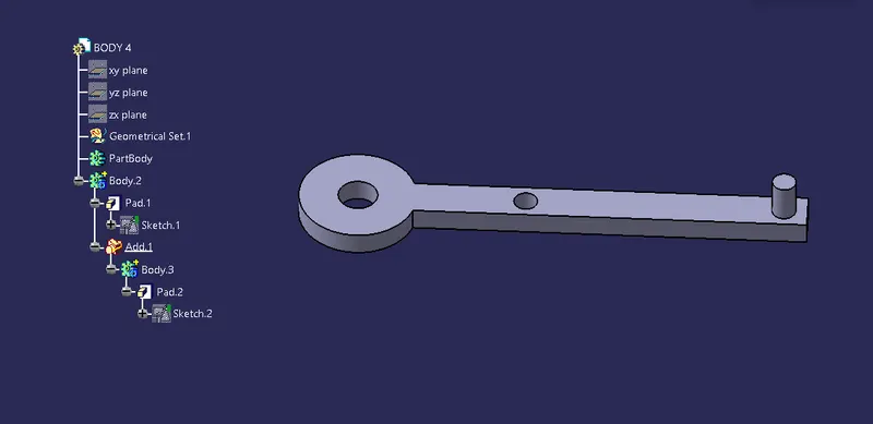
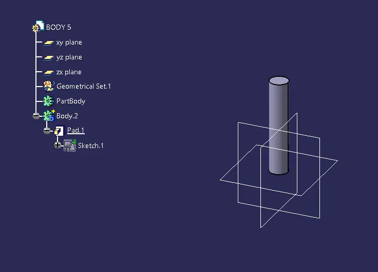
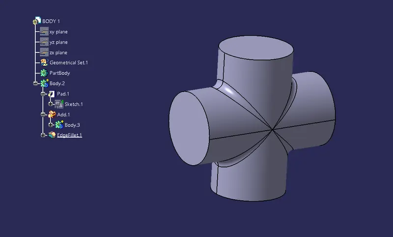
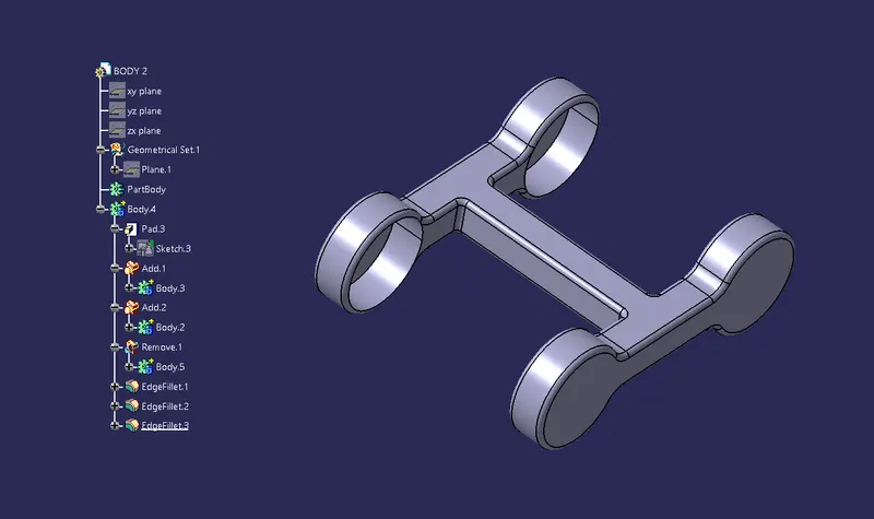
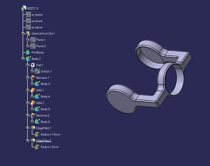
Create a main folder and start modeling each parts in part design seperately. Ensure proper naming for each cad part model and save it to the main folder. For each models use correct gromentrical and dimensional constrains for getting fully defined sketch.
STEP 2
ASSEMBLY
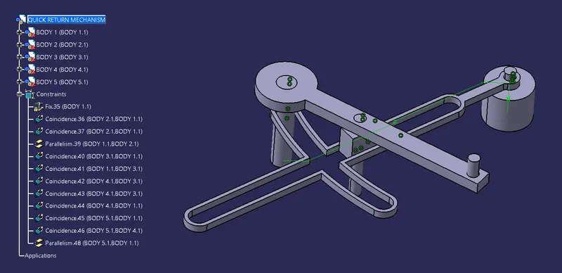
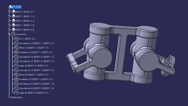
After creating part models and saving them in the main folder open the assembly workbench and insert the each models by selectig the Existing compenent feature in the Product structure tools toolbar. When the first cad model is imported into the assembly workbench, fix that compenent by using FIX component in the constraints toolbar, so that we can restict the degree of freedom.Then, insert the second model like wise and do the constraints to get zero degree of freedom. Same way we have to do for all the cad model parts to bring the final assembly.
STEP 3
DRAFTING
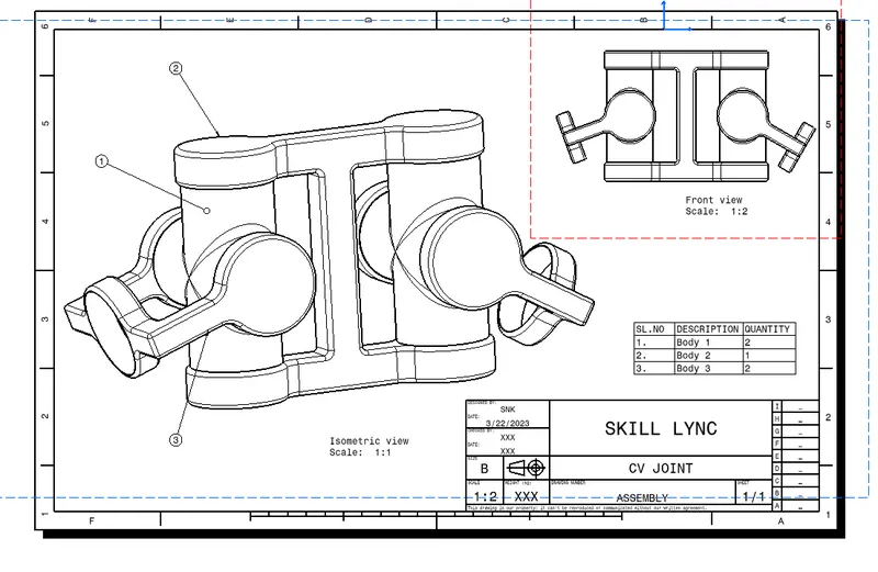
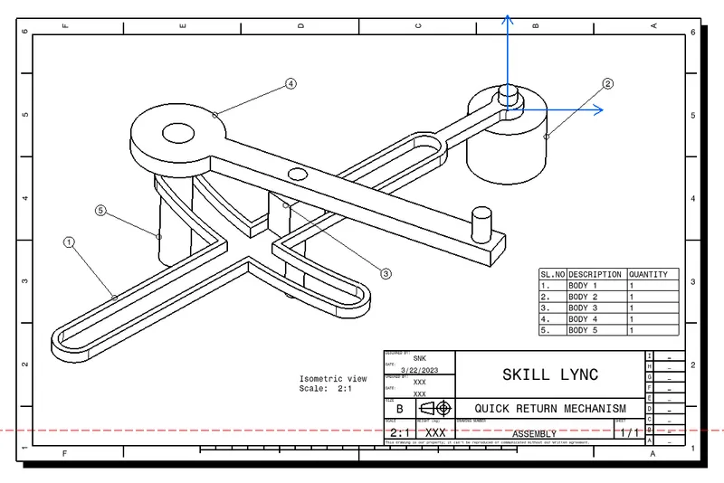
After part modeling and assembly, open drafting workbench. In that, first go to the sheet properties and change the projection method from Third angle standart to First angle standard. Then, check the scale ratios and perform the drafting for each part models and assembly.
CV JOINT
All the step to perform the part models, assembly and drafting is done as the same way as did in the quick return mechanism procedure.
STEP 1
PART MODEL
STEP 2
ASSEMBLY
STEP 3
DRAFTING