Week 12- Final project
1)
OBJECTIVES
- Create the Door trim Panel Plastic component through the given Class-A surface. To begin with, the tooling axis for the given Class A Surface should be created meeting the requirements of the draft angle and at the end perform the Draft analysis on the model.
- To Create the Heat stakes and locators in the lower substrate considering the design rules.
- To Create the Dog house in the lower substrate and assemble the pushpin considering the design rules.
- To Create the Flanges to connect all the design features together considering the design rules.
SPECIFICATIONS OF PLASTIC COMPONENT
- Required strength
- Specific service temperature range
- Exposure to chemicals and harsh environments
- Appearance requirements
- Dimensional tolerances
- Required agency approvals
- Processing method
- Assembly method
- Recyclability considerations
MANUFACTURING OF PLASTIC COMPONENTS
INJECTION MOULDING PROCESS
Injection molding is the most widely used molding process for thermoplastics. It is based on the ability of thermoplastic materials to be softened by heat and to harden when cooled. The process thus consists essentially of softening the material in a heated cylinder and injecting it under pressure into the mould cavity, where it hardens by cooling. Each step is carried out in a separate zone of the same apparatus in the cyclic operation.
APPLICATIONS
Solid Wide neck, Flat Product is made like bucket, Automobile & Industrial parts,Moulded chairs, Computer/ TV/ Radio Cabinets, Washing machine Cabinets, Mobile, Powertool housings etc. Moulded House hold items etc. by injecting molten thermoplastic material into a closed mould which is relatively cool.
ADVANTAGES OF INJECTION MOULDING
- Parts can be produced at high production rates.
• Large volume production is possible.
• Relatively low labour cost per unit is obtainable.
• Process is highly susceptible to automation.
• Parts require little or no finishing.
• Many different surfaces, colours, and finishes are available.
• Good decoration is possible.
• For many shapes this process is the most economical way to fabricate.
• Process permits the manufacture of very small parts which are almost impossible to
fabricate in quantities by other methods.
• Minimal scrap loss result as runners, gates, and rejects can be reground and reused.
• Same items can be moulded in different materials, without changing the machine or
mould in some cases.
• Close dimensional tolerances can be maintained.
• Parts can be moulded with metallic and non-metallic inserts. Parts can be moulded in a combination of plastic and such fillers as glass, asbestos, talc and carbon. The inherent properties of the material give many advantages such as high strengthweight rates, corrosion resistance, strength and clarity
TYPES OF PLASTIC
Plastics come in thousands of varieties with different base chemistries, derivatives, and additives that are formulated to cover a wide range of functional and aesthetic properties. To simplify the process of finding the material best suited for a given part or product, let’s look first at the two main types of plastic: thermoplastics and thermosets.
THERMOPLASTICS
Thermoplastics are the most commonly used type of plastic. The main feature that sets them apart from thermosets is their ability to go through numerous melt and solidification cycles without significant degradation. Thermoplastics are usually supplied in the form of small pellets or sheets that are heated and formed into the desired shape using various manufacturing processes. The process is completely reversible, as no chemical bonding takes place, which makes recycling or melting and reusing thermoplastics feasible.
Common types of thermoplastic materials:
- Acrylic (PMMA)
- Acrylonitrile butadiene styrene (ABS)
- Polyamide (PA)
- Polylactic acid (PLA)
- Polycarbonate (PC)
- Polyether ether ketone (PEEK)
- Polyethylene (PE)
- Polypropylene (PP)
- Polyvinyl chloride (PVC)
THERMOSETTING PLASTICS
In contrast with thermoplastics, thermosetting plastics (also referred to as thermosets) remain in a permanent solid state after curing. Polymers in thermosetting materials cross-link during a curing process that is induced by heat, light, or suitable radiation. This curing process forms an irreversible chemical bond. Thermosetting plastics decompose when heated rather than melting, and will not reform upon cooling. Recycling thermosets or returning the material back into its base ingredients is not possible.
Common types of thermoplastic materials:
- Cyanate ester
- Epoxy
- Polyester
- Polyurethane
- Silicone
- Vulcanized rubber
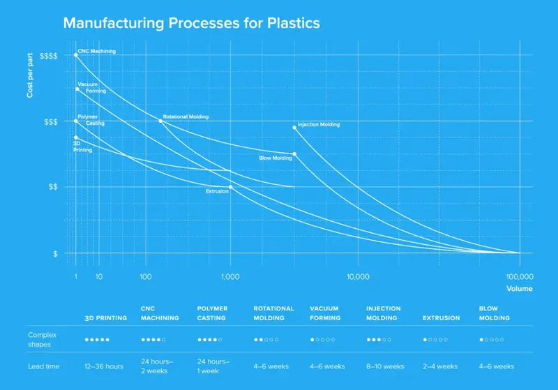
TYPES OF MANUFACTURING PROCESSES
- 3D Printing
- CNC Machining
- Polymer Casting
- Rotational Molding
- Vacuum Forming
- Injection Molding
- Extrusion
- Blow Molding
MANUFACTURING STEPS FOR PLASTIC COMPONENTS
- Mold preparation: The mold is coated with a release agent to facilitate demolding, and often preheated to a material specific temperature.
- Casting: The synthetic resin is mixed with a curing agent and poured or injected into the mold, where it fills the mold cavity.
- Cure: The casting cures in the mold until it solidifies (subjecting the mold to heat can accelerate the cure time for certain polymers).
- De-mold: The mold is opened and the cured part is removed.
- Trimming: Casting artifacts like flash, sprues, and seams are cut or sanded away.
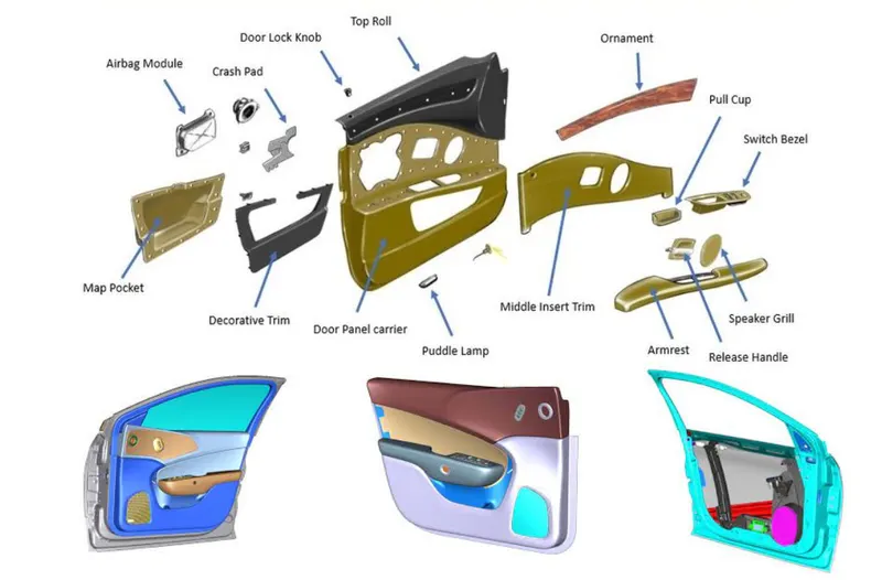
SIDE DOOR TRIM PANEL
GIVEN CLASS A SURFACE
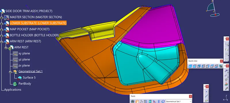
- Check the connectivity of the Class A Surface
- Ensure that there is no gap between the component, using join command.
- We can visually check it or by clicking boundary command.
- Therefore first check completed.
TOOLING AXIS CREATION IN ARM REST
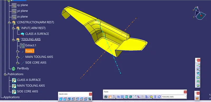
- Find the tooling axis of the component.
- The tooling axis is nothing but the mould opens or cavity opens.
- Check visaully which is the best possible tooling axis.
- Check all three axis.
- Now perform the Draft analysis using the Featured Draft Analysis tool in the tools.
- Then after opening the draft analysis tool box go for the compass and place the compass alinged to tooling axis and click on the lock symbol after alinging and further click on the surface.
BISECTING METHOD
- Bisecting method is basically use to find the proper tooling axis using the dummy tooling axis.
- In Bisecting method, bisecting line is used which either bisect the two line or it will show error which means the two lines are parallel to each other.
- In order to know whether the particular surface is toolable or not we intersect the surface with the respective plane and get a sketch which consist of two lines and with the help of bisecting line option we bisect the line which creates a line at the mid point of the two lines.
- Like wise we create tooling clearing axis for x and y which will be used to create the main tooling axis using the bisecting line option in in the line comand.
DIRECT OFFSETTING OF CLASS A SURFACE
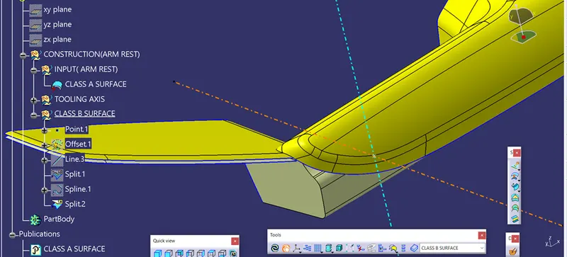
- Offset the class a surface 2.5mm direclty.
- Some patches will form after offsetting.
- Remove the filleted region for closing the patches.
- Define the boundary and extrapolate to required length.
- Now trim the surfaces to required surfaces
- Now provide proper fillet the surface to required amount
SWEEPED C SURFACE
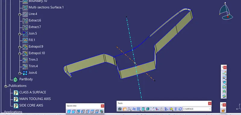
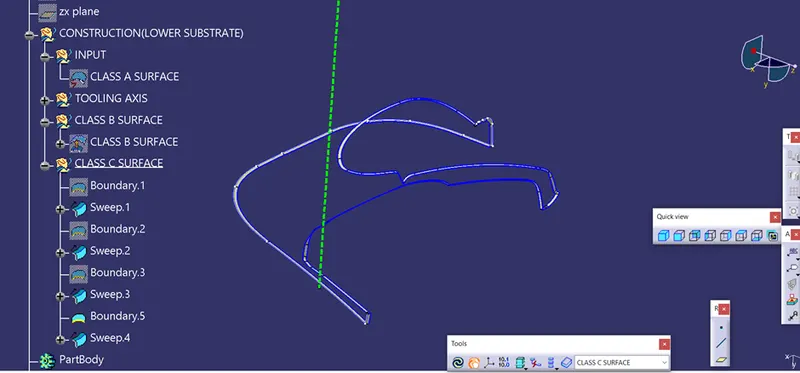
- Extract the boundary of the class-A surface.
- Extract the boundary of the holes on the class-A surface.
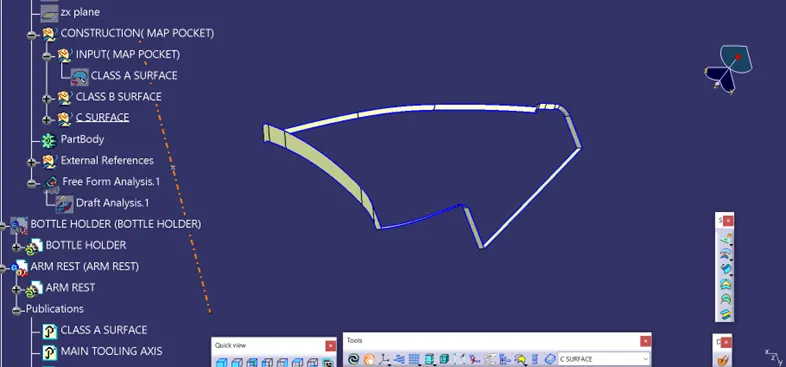
- Use sweep command on the boundaries one by one to get the class-C surface.
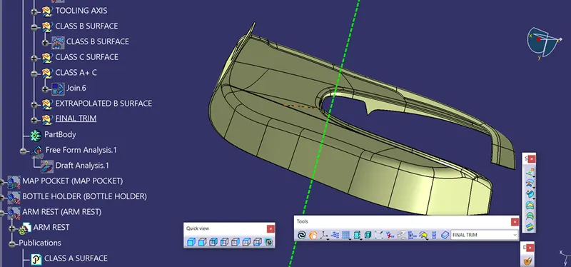
- Join the class-A and class-C surfaces together
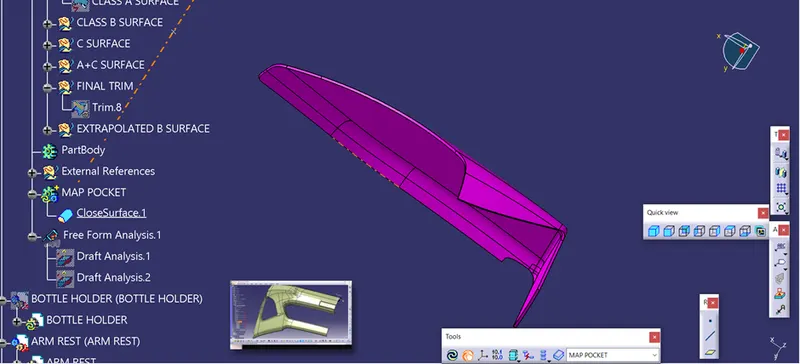
- Trim the class-B surface with the join created earlier.
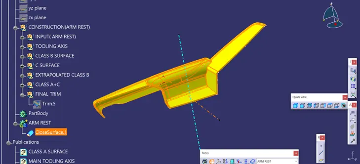
FINAL CLOSED SURFACE FOR ARM REST
DRAFT ANALYSIS OF ARM REST
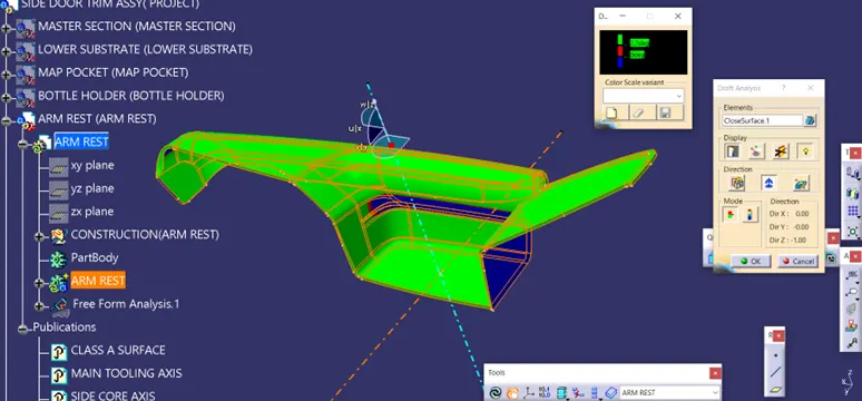
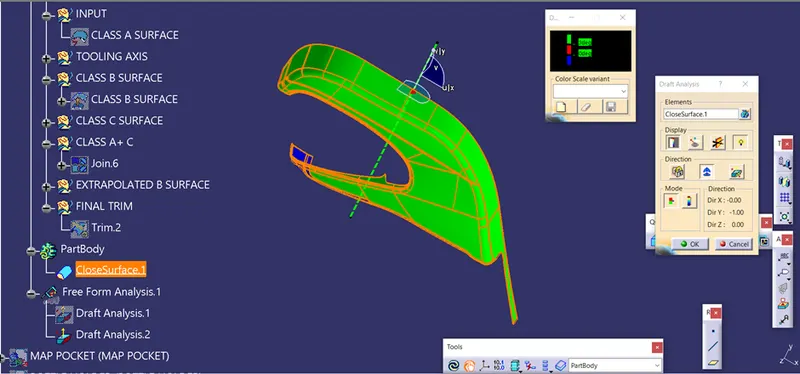
Plastic parts are always designed with a taper or draft in the direction of mold movement to allow part ejection or removal from the mold. Since plastics shrink when cooled, it is common for parts to shrink (or grip tightly) to cores. A good definition for draft would be: the degree of taper of a side wall or rib needed to allow the molded plastic part to be removed from the metal mold. Without proper draft, plastic parts may be difficult to remove from the mold. A draft angle of 1/2 degrees is regarded as minimum for most applications. Draft angles of 1 1/2 to 2 degrees per side are considered normal for plastic injection molding.
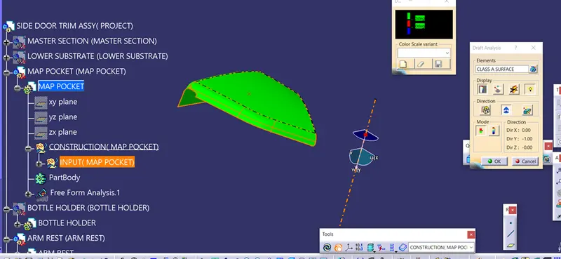
- Go to insert< analysis< feature draft analysis.
- Align the tooling axis with the compass.
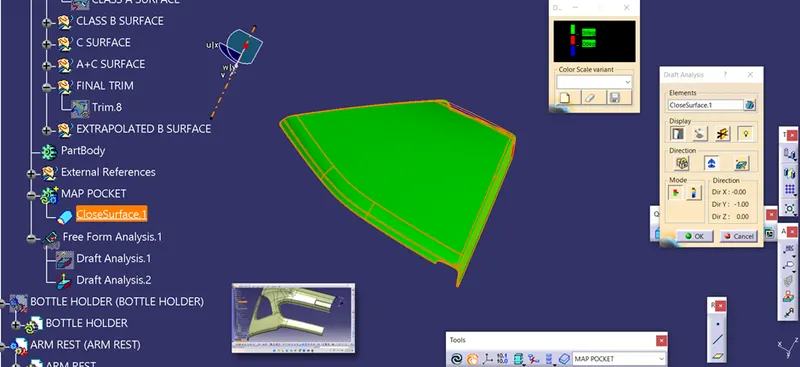
- Click on the surface and see that the surface is within the permissible limit of the draft values.
- The surface should be green and in the column proper value (3deg) should be inserted.
MAP POCKET CLASS A SURFACE DRAFT ANALYSIS
SWEEPED C SURFACE OF MAP POCKET
FINAL CLOSED SURFACE FOR MAP POCKET
MAP POCKET CLOSED SURFACE DRAFT ANALYSIS
CLASS A SURFACE OF BOTTLE HOLDER
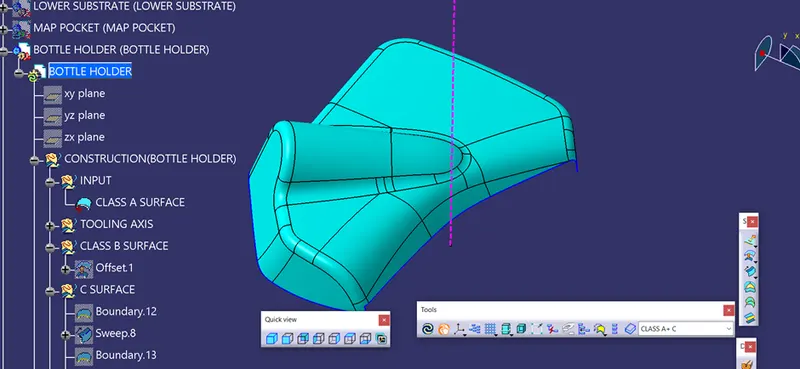
CLASS A + C SURFACE OF BOTTLE HOLDER
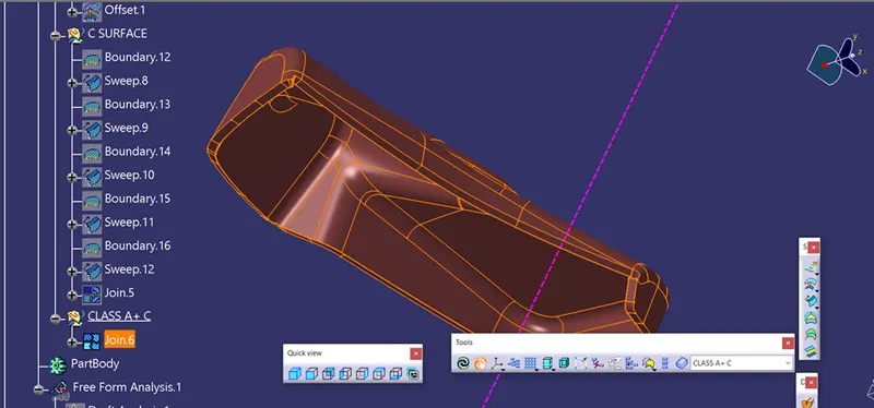
SWEEPED C SURFACE OF BOTTLE HOLDER
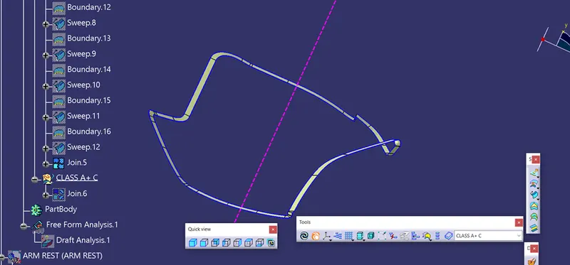
BOTTLE HOLDER CLOSED BODY
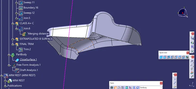
BOTTLE HOLDER CLOSED BODY
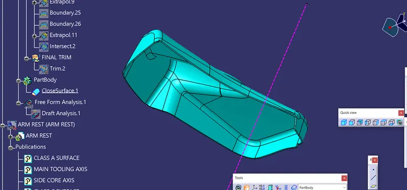
BOTTLE HOLDER DRAFT ANALYSIS
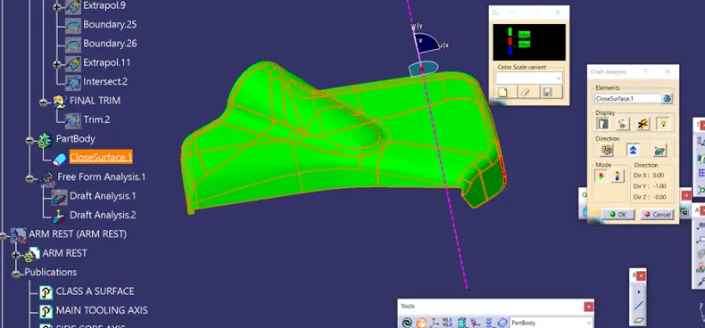
LOWER SUBSTRATE CLASS A SURFACE
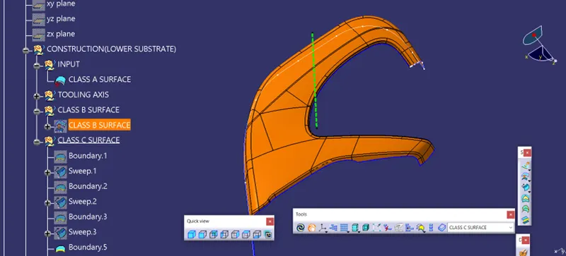
LOWER SUBSTRATE DRAFT ANALYSIS
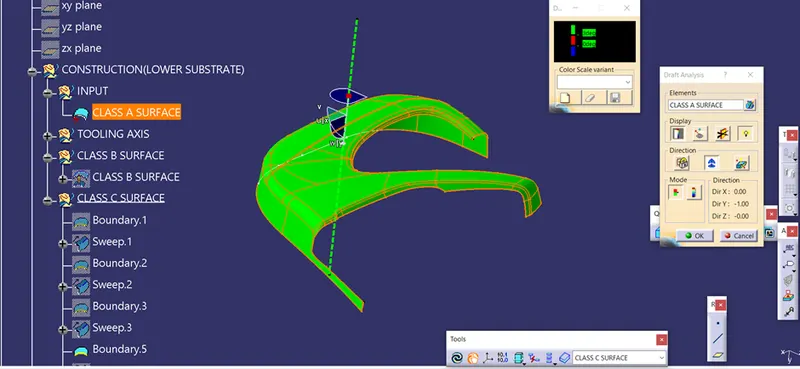
LOWER SUBSTRATE A + C SURFACE
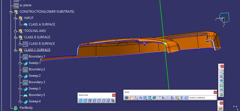
LOWER SUBSTRATE SWEEPED C SURFACE
LOWER SUBSTRATE CLOSED BODY
LOWER SUBSTRATE CLOSED BODY
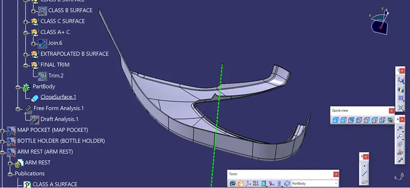
LOWER SUBSTRATE CLOSED BODY
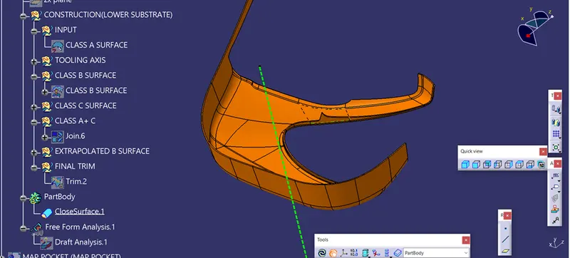
LOWER SUBSTRATE DRAFT ANALYSIS
PLASTIC DESIGN CONSIDERATIONS
Many times the stiffness of a part must increase because of the load applied to the part design. One of the easiest ways to cure this problem is change the part geometry by adding ribs. The use of ribs is a practical way and economical means of increasing the structural strength of a part. But there are guidelines that govern adding ribs without causing sink marks or surface blemishes to your parts.
HOLES
Many times the stiffness of a part must increase because of the load applied to the part design. One of the easiest ways to cure this problem is change the part geometry by adding ribs. The use of ribs is a practical way and economical means of increasing the structural strength of a part. But there are guidelines that govern adding ribs without causing sink marks or surface blemishes to your parts.
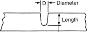
L= 2D for Diameters Less than 3/16" dia. core pins
L= 4D for Diameters More than 3/16" dia. core pins
The coring of holes is easy when the axis is parallel to the parting line. But when holes and other features run perpendicular to the parting line then retractable cores (or cams) are required. Split pins and cores (called passing steel shutoffs) can be used to create some of the features. The designer needs to be aware of the problems of side action cores and the added expenses associated with these types of molds. With a little understanding of how the mold opens and where the parting line will exist, these costly features can be modified. Rule of thumb: whenever possible all design features should be incorporated in the same direction of the mold opening so that cam action can be avoided.
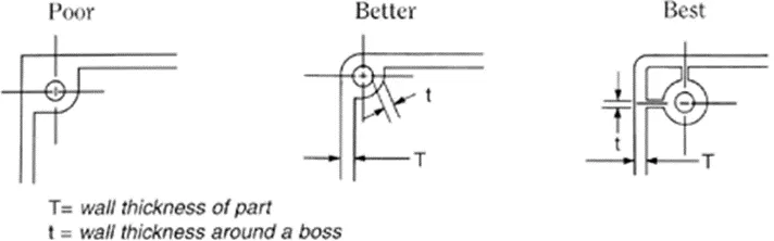
BOSSES
Bosses are used for locating, mounting, and assembly purposes. There are boss design guidelines that must be followed to insure the highest quality in molded parts. Again, one of the main points to consider is nominal wall thickness. Too many times bosses are designed with thick wall sections that can affect the appearance of the plastic part and the final product.
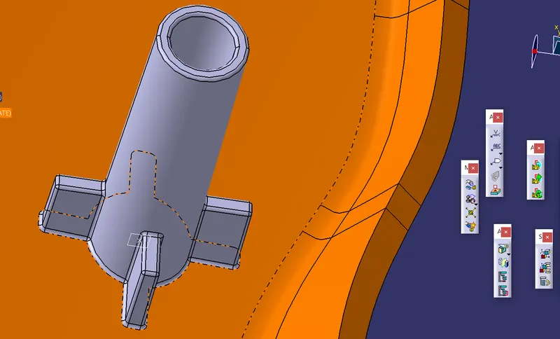
HEAT STAKES DESIGN
- Heat Staking is a pulsed-heat process to join two or more parts out of which one at least is made of plastic.
- The process is to deform the plastic material using heat and force at a set process time.
- The bond is made by partially de-forming the plastic part in order to fix the other.
- Heat Staking makes it easy to bond metal to plastic and is commonly used in high volume/low cost applications such as automotive, IT and consumer appliances.
- Similar and dissimilar materials may be joined: metal to metal, plastic to plastic, metal to plastic
- Accurate control operating within a small process window
- Local heating resulting in no damage to surrounding materials
- Processing of glass-filled materials
- No mechanical vibration
- Many heat-stake shapes possible through custom designed tools
DEVELOPED HEAT STAKE
LOCATORS DESIGN
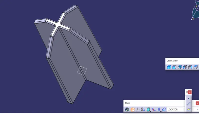
- Locators are the supporting member.
- Minimum 2 locators are required for the plasic design.
- 4 way and 2 way locators are available.
- 4 way locators which arrests the 4 degrees of freedom by four ribs junctional together.
- Locators height should be higher than heat stakes.
DOG HOUSE CREATION
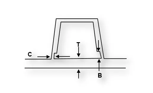
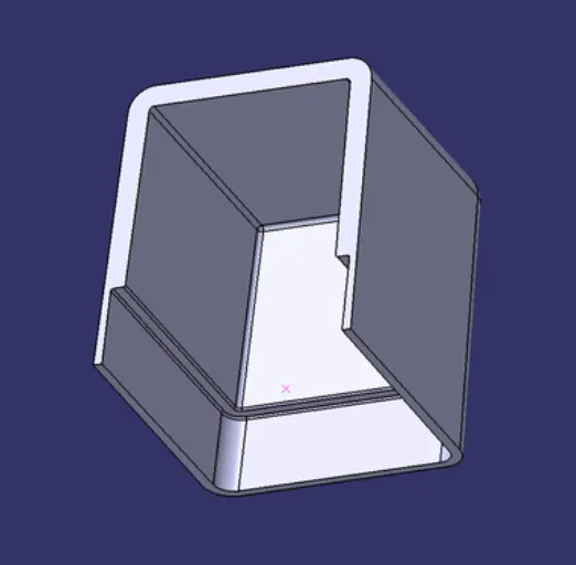
- Dog houses are designed to avoid SINK MARK created on the CLASS-A surface by screw bosses and to solve the length issues when giving screw bosses which need to be assembled to other components.
- It is also useful when perpendicular screw bosses are required on the part to the tooling direction.
- C thickness should be 40% of the main wall thickness T
- Minimum width of the dog house is 12 mm.
- Height of B should be 3-6 mm
- Minimum draft for the do house degrees 5 degrees to die draw.
CORING
- • Coring can help in making the wall sections uniform, and eliminate the problems
associated with non-uniform walls.
• Prefer & design shell type object
• Use coring wherever possible to adjust uniform wall thickness
DEVELOPED DOG HOUSE
DRAFT ANALYSIS ON DEVELOPED DOG HOUSE
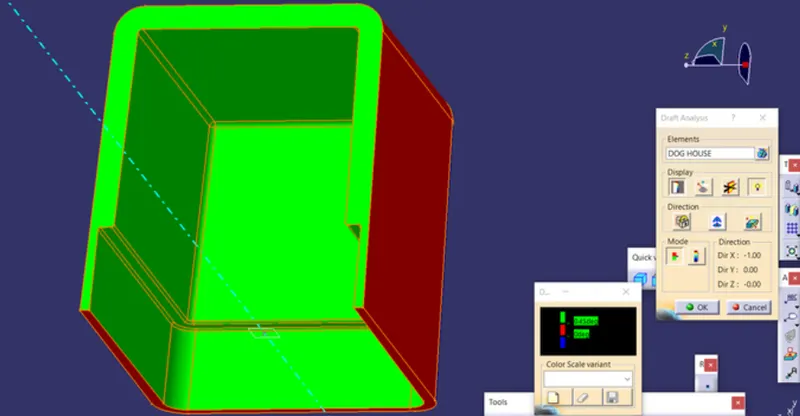
FLANGE CREATION IN ARM REST
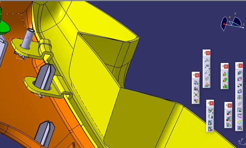
FLANGE CREATION IN BOTTLE HOLDER
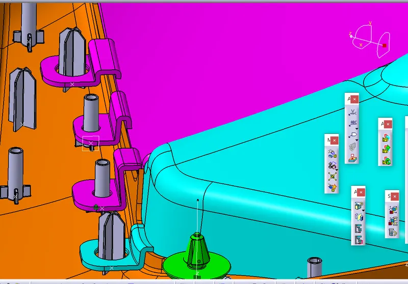
FLANGE CREATION IN MAP POCKET
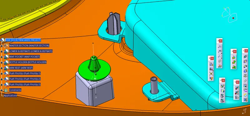
ASSEMBLED DOG HOUSE WITH PUSHPIN
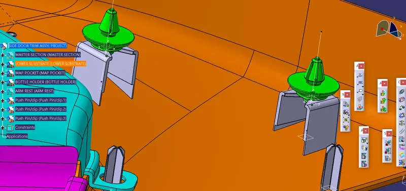
FINAL DRAFT ANALYSIS OF LOWER SUBSTRATE WITH ENGINEERING FEATURES
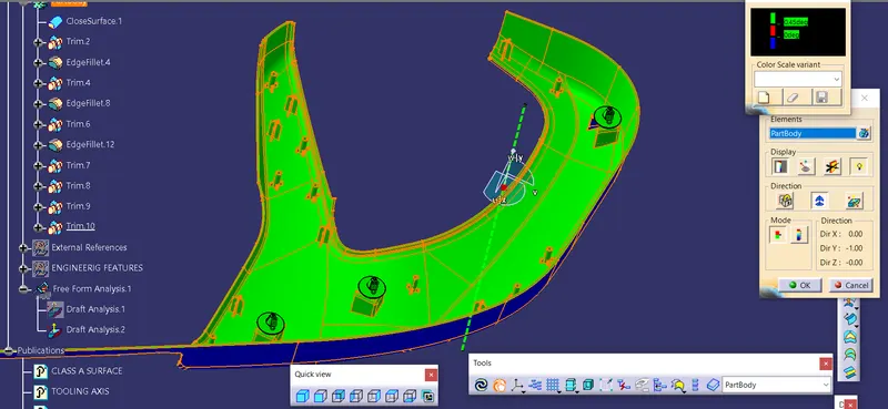
FINAL DRAFT ANALYSIS OF MAP POCKET WITH ENGINEERING FEATURES
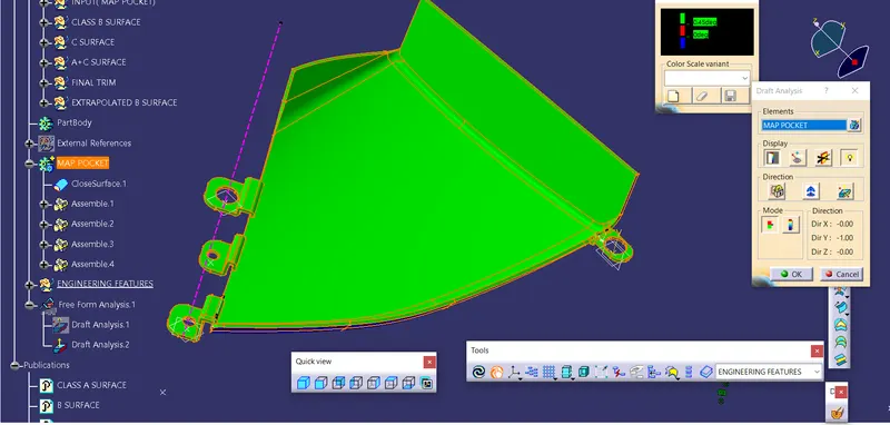
FINAL DRAFT ANALYSIS OF BOTTLE HOLDER WITH ENGINEERING FEATURES
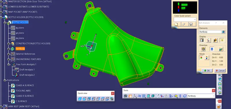
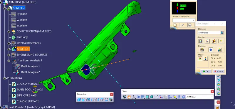
FINAL DRAFT ANALYSIS OF ARM REST WITH ENGINEERING FEATURES
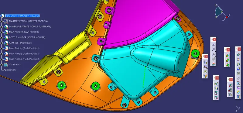
FINAL MODEL OF SIDE DOOR PANEL
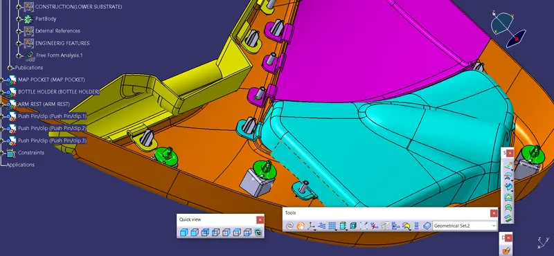
FINAL MODEL OF SIDE DOOR PANEL
DESIGN TREE STRUCTURE
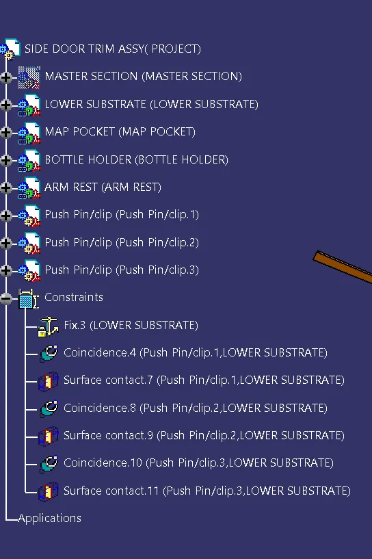
EXPANDED DESIGN TREE STRUCTURE
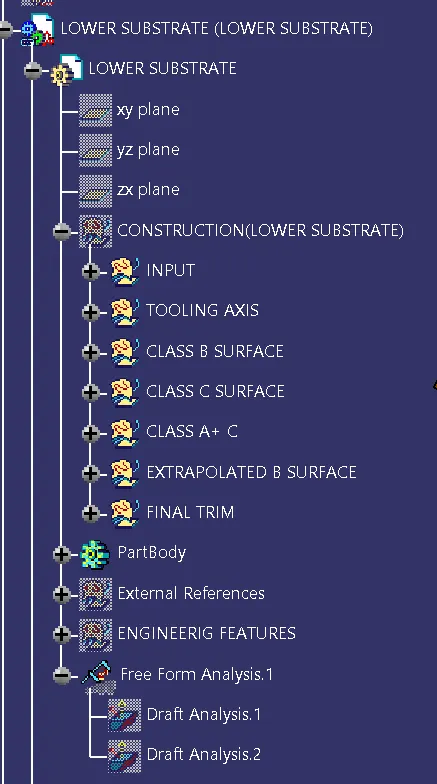
EXPANDED DESIGN TREE STRUCTURE
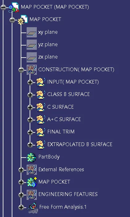
EXPANDED DESIGN TREE STRUCTURE
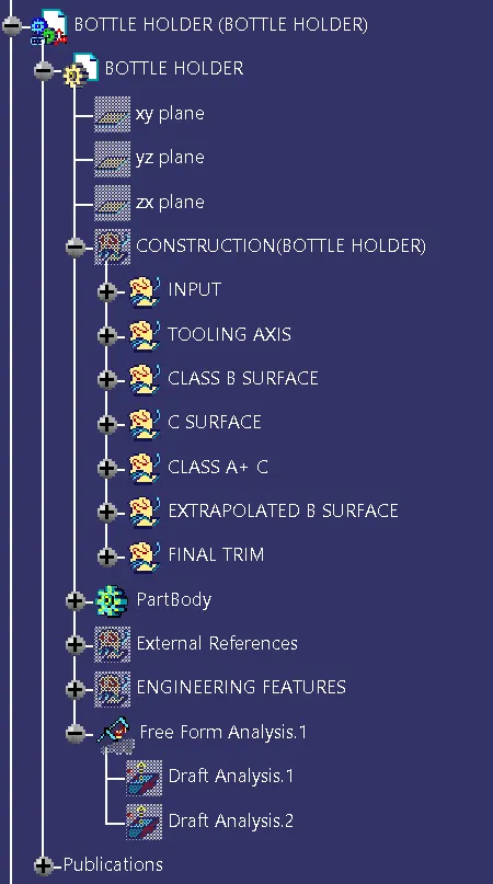
EXPANDED DESIGN TREE STRUCTURE
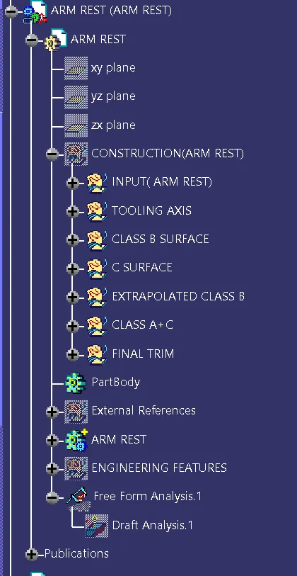
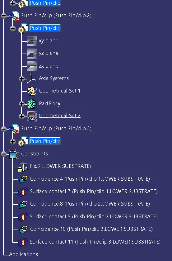
EXPANDED DESIGN TREE STRUCTURE
CONCLUSIONS
- Successfully created Side Door trim Panel plastic component.
- Successfully performed draft analysis for class a surface and solid close surface.
- Successfully Extracted closed solid body from plastic surface.
- Created the Heat stakes and locators in the Door Trim Lower substrate considering the design rules.
- Created the Dog house in the Door Trim Lower substrate considering the design rules.
- Created flanges in Arm rest, map pocket and bottle holder.
- Successfully performed final draft analysis for solid close surface with engineering features.