Project 1
1)
PROJECT : Development of a Forward energy-based fuel Consumption Model of a Conventional Vehicle
Submitted by : Manu Mohan V
AIM :
- To develop the block diagram of the vehicle model using simulink.
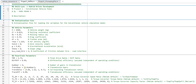
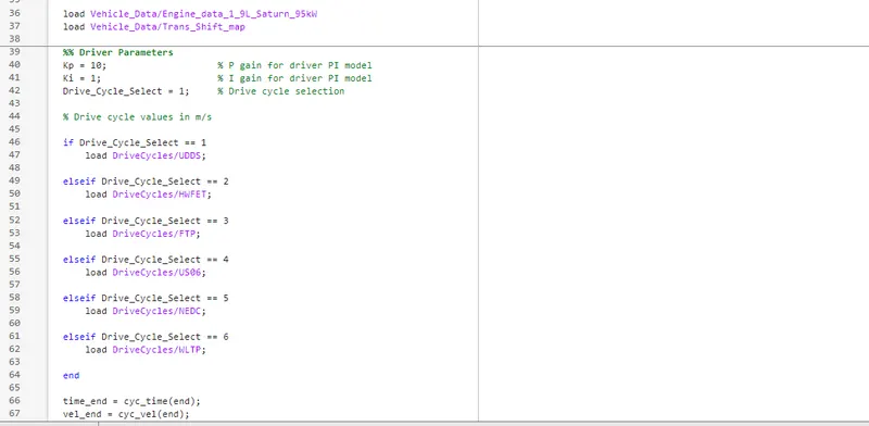
- To define the script in MATLAB for running the simulink model.(ie load variables).
- Tabulate the fuel economy for UDDS and HWFET cycle.(Using UDDS & HWFET Data)
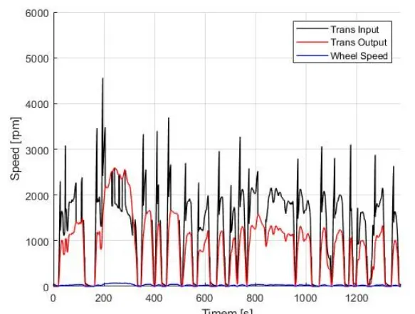
- Plot the time trace for engine includes transmission input, transmission output and wheel speed on one plot.
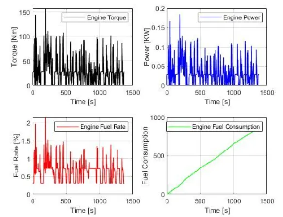
- Using subplots plot engine torque, engine power. fuel rate and fuel consumption.
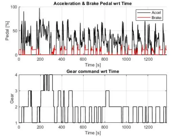
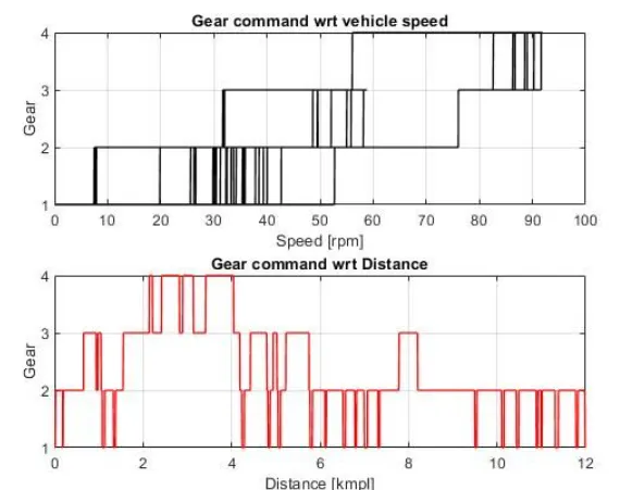
- Using subplots to plot accelerator and brake pedal, gear command, vehicle desired and actual speed, vehicle distance.
- On the engine fuel map we have to plot engine operating points.
- We have to generate plots for both drive cycles.
- We have to do Study of Conventional vehicle simulink model and to create graphs
CONVENTIONAL VEHICLE
Conventional vehicles utilize an inside combustion motor fueled by gasoline or diesel to control the wheels. Power is utilized for a few embellishments, but isn't utilized to move the vehicle. It uses IC engine fueled by deisel to power the wheels.The principle of heat released is employed by heat engine for combustion.In the combustion chamber a gas is expanded which pushes against piston thereby creating force and torque.In the engine the chemical energy of fuel is getting converted into heat. It provides useful work.Mainly petroleum fuels are employed. Internal combustion engine basically a heat engine , uses the principle of heat release through combustion of the fuel with in an oxidizer in a combustion chamber, to create expanding gases which pushes against a piston, creating force and torque output. The piston is connected with crank shaft which converts chemical energy in to mechanical energy
In our project a 4 stroke reciprocating engine.The engines are normally represented by thermodynamic cycles.The thermodynamic cycle consist of otto cycle and diesel cycle. otto cycle is employed for SI engines.THe diesel cycle is employed for CI engines.
ENGINE PERFORMANCE ENHANCEMENT
The engine performance can be maximised by:
- High Brake efficiency( Fuel conversion and mechanical efficiency)
- High volumetric efficiency, improved engine breathing.
- Using fuels with higher efficiency content.
- Maximize Air to fuel ratio( A/F) that can have stable combustion in the engine.
- Increasing the inlet air density by using forced induction and cooled intake.
CONVENTIONAL POWERTRAIN EFFICIENCY
The conventional powertrain is composed of a transmission framework, motor cooling fans and pump frame-works includes with engine management and Transmission.The conventional power train efficiency is defined as the engine converts chemical energy to mechanical energy thereby power is getting generated.The process employed is combustion.The energy input is fuel consumption and it has a efficiency.
INSTANTANEOUS FUEL CONSUMPTION
It deals with the modeling of multi domain systems through the use of a unified approach based on a ordinary differential and algebraic equation describing the static and dynamic effects.
SYSTEM VARIABLES
The system variables includes effort,flow and control.These variables are used to the develop the model
Effort variables : Effort variables are generalized force variables. It includes
- Engine torque
- pump torque
- axle torque
- brake torque
- transmission torque
- Tractive force
- Rolling resistance force
- grade force
- Aerodynamic force
- voltage
- heating values
Flow variables : flow variables are generalized force or velocity variables . it includes
- Vehicle velocity
- Wind velocity
- Wheel speed
- Transmission speed
- Engine speed
- Current
- Mass flow rate
Control variables : Control variables are the product of effort and flow variables. It includes
- Wheel power
- Transmission power
- Differential power
- Engine power
- Energy
MATLAB CODE FOR VEHICLE PARAMETERS
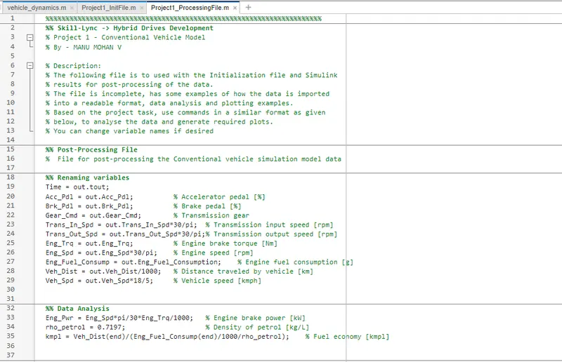
MATLAB CODE FOR POST PROCESSING VEHICLE MODEL
BLOCK DIAGRAM FOR DRIVER, CONTROLLER & VEHICLE PLANT
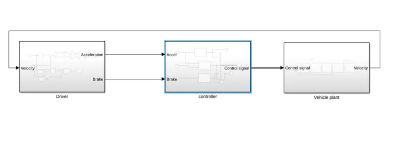
The basic block diagram for conventional vehicle system. The input action is applied by the driver which is controlled by the controller and the control signal is analyzed by the vehicle plant. Feedback system has to control the vehicle speed.
VEHICLE PLANT SIMULINK MODEL
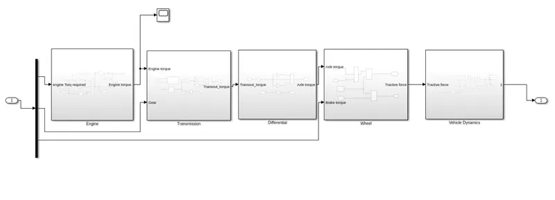
It will pass through all the components that converts power to mechanical work output, includes the engine, transmission, driveshaft, differentials, axles; basically anything from the engine through to the rotating wheels.To model fuel consumption a map based model is employed.It depends on maximum and minimum torque.In these model we take engine torque, gear selector from controller for transmission of gear ratio. We will multiply the ratio with transmission torque, positive, negative torque that gives transmission input speed.The torque converter in the transmission system will connect engine with the transmission system.
VEHICLE DYNAMICS SIMULINK MODEL
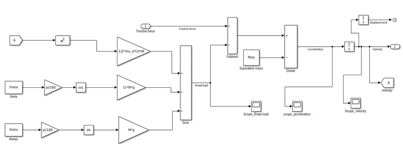
The vehicle dynamics is the movement of the vehicle created by the directing activity, through which the vehicle is able of autonomous movement . It clarifies the movement of the vehicle for a given direct input, and clarifies the mechanics of vehicle movement.
WHEEL SIMULINK MODEL
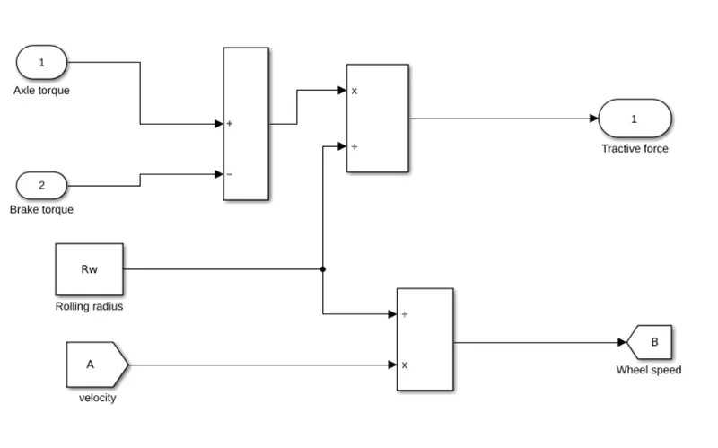
A drive wheel could be a wheel of a engine vehicle that transmits drive, changing torque into tractive constrain from the tires to the street, causing the vehicle to move. The powertrain conveys sufficient torque to the wheel to overcome stationary powers, coming about within the vehicle moving advances or in reverse.
DIFFERENTIAL SIMULINK MODEL
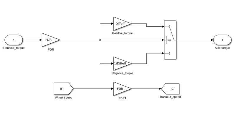
The differential may be a framework of gears that permits different drive wheels (the wheels to which control is conveyed from the motor) on the same hub to turn at distinctive speeds, such as when the car is turning. The output is taken from the transmission. This is then multiplied by differential ratio and to multiply the axle torque.The magnitude of axial torque is less than the transmission torque.In the model depicted below the transmission torque is taken from the differential and brake torque from the controller. The tractive force is obtainedfrom brake torque when it is subtracted and multiplied with rolling radius.The wheel speed is velocity.
TRANSMISSION SIMULINK MODEL
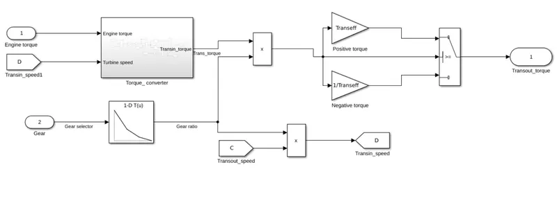
The transmission is for changing over both speed and energy into control that at that point gets the whole car moving and its primary point is to form the motor as effective as possible by lessening the sum of fuel utilization while getting the finest sum of control.
TORQUE CONVERTER SIMULINK MODEL
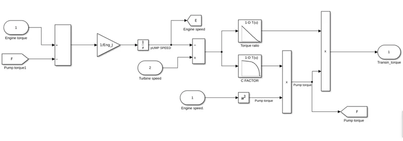
A torque converter could be a sort of liquid coupling that exchanges turning control from a prime mover, like an inner combustion motor, to a pivoting driven stack. In a vehicle with an programmed transmission, the torque converter interfaces the control source to the sink.
ENGINE SIMULINK MODEL
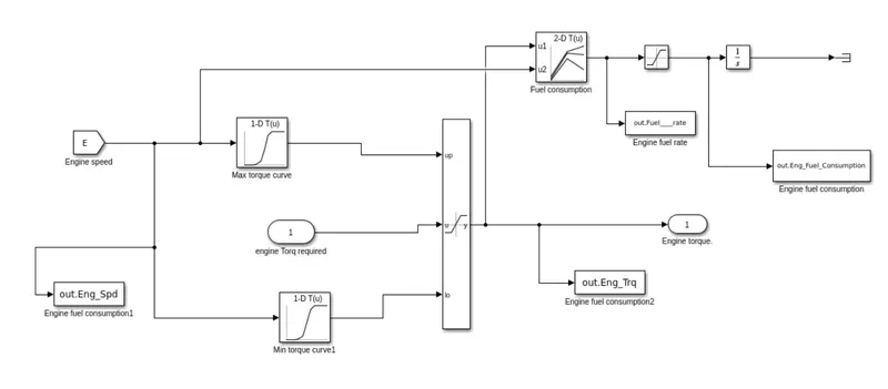
Particularly, an internal-combustion engine could be a warm motor in that it changes over vitality from the warm of burning gasoline into mechanical work, or torque. That torque is connected to the wheels to create the car move.
DRIVER SIMULINK MODEL
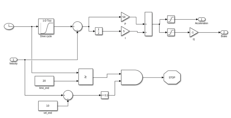
Driver model controls the velocity of the vehicle. The manual action of acceleration and brake action allows the vehicle motion.
CONTROLLER SIMULINK MODEL
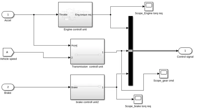
Controller model includes engine control unit, Transmission control unit and brake control unit.
ENGINE CONTROL UNIT SIMULINK MODEL
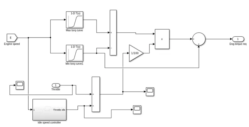
Engine control unit (ECU) is an electronic control unit that guarantees the ideal work of an inside combustion motor. It controls fuel supply and infusion, fuel-to-air proportion, start, sit still speed, and the timing of valve opening and closing.
IDLE SPEED CONTROLLER SIMULINK MODEL
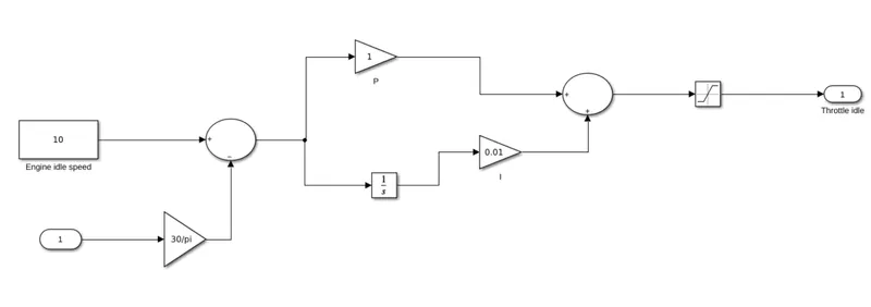
The idle speed control mode is utilized to anticipate motor slow down amid sit still. The objective is to permit the motor to sit still at as moo an RPM as conceivable however keep the motor from running unpleasant and slowing down when power-consuming embellishments, such as air-conditioning compressors and alternators, turn on.
TRANSMISSION CONTROL SIMULINK MODEL
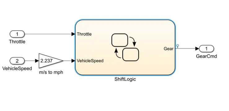
A transmission control module is an electronic component within the transmission that is responsible for interpreting electrical signals from sensors in other parts of the vehicle.
BRAKE CONTROL SIMULINK MODEL
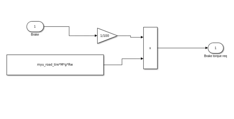
The brake control unit operate independently, but the trailer electric brakes must be connected to the tow vehicle power supply and controlled by a brake control unit or electric brake controller. A brake controller, as the term suggests, is an electronic device that activates and controls the trailer's electric brakes.
1) UDDS DRIVE CYCLE
MATLAB CODE
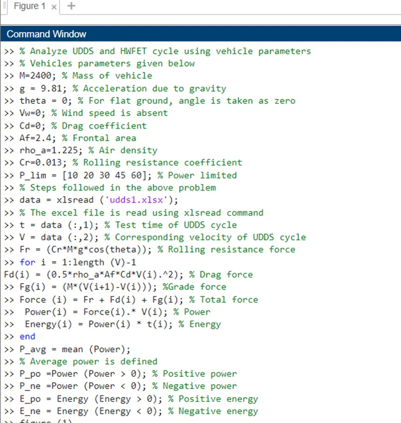
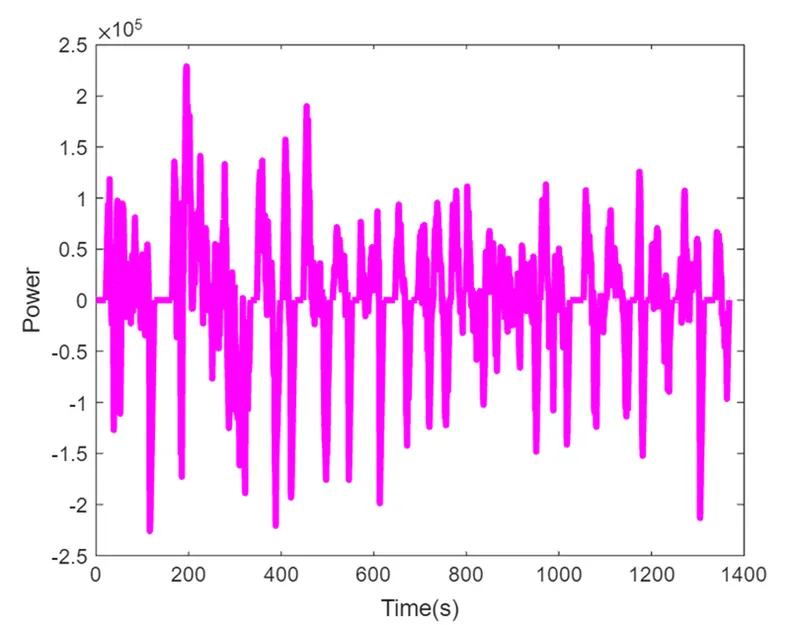
PLOT FOR POWER Vs TIME (UDDS)
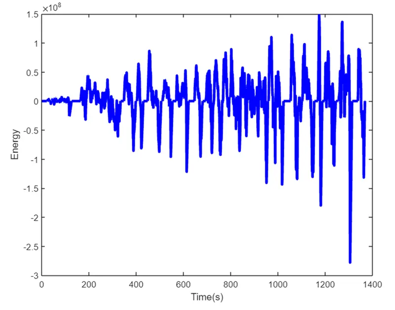
PLOT FOR ENERGY Vs TIME (UDDS)
2) HWFET DRIVE CYCLE
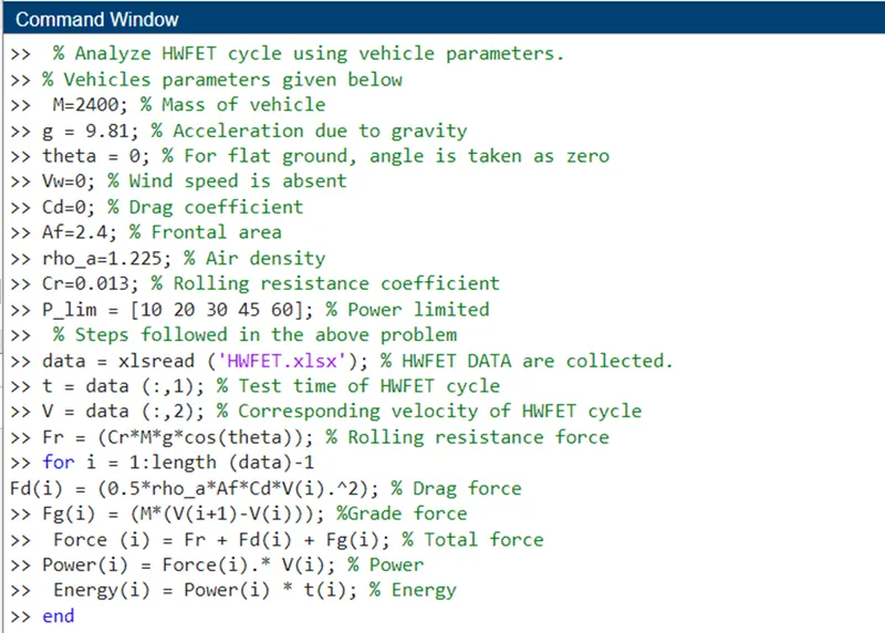
MATLAB CODE
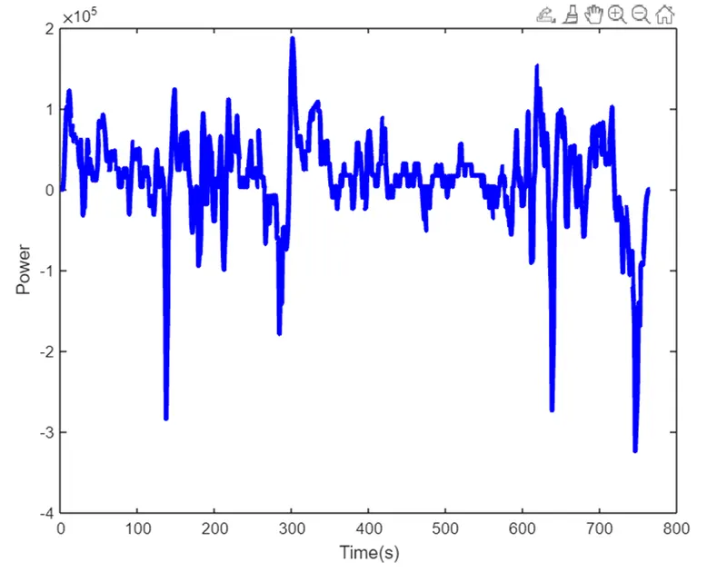
PLOT FOR POWER Vs TIME (HWFET)
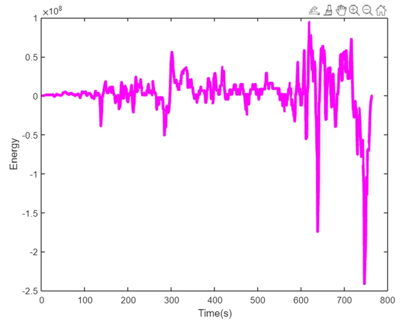
PLOT FOR ENERGY Vs TIME (HWFET)
MATLAB CODE VEHICLE CHARACTERISTICS PLOT