Project - Speed Control of a Direct Current (DC) motor
1)
PROBLEM STATEMENT:
DESIGN A SIMULINK MODEL FOR DC MOTOR SYSTEM AND IMPLEMENT PROPORTIONAL, INTEGRAL, AND DERIVATIVE (PID) CONTROL GAINS. DEVELOP AND TEST A CONTROLLER TO MAINTAIN A DESIRED SPEED FOR THE MOTOR.
ANSWER:
- Speed of a dc motor can change manually or by using automotive control systems
- External load on the shaft will causes the variation of the speed of dc motor.
- The speed variation will cause damage to the automotive system. So we should control the speed of dc motor with in an optimum level.
- The dc motor speed is influenced by armature terminal voltage(Va), External resistance on the armature circuit(Ra) & flex in the circuit.
- There are two methods are available to control the speed of dc motor.
- Armature control method; A resistance is connected with series with the armature circuit.
- Field control method; These motors are operated above normal speed. Higher speed is obtained in less torque.
SIMULINK MODEL FOR DC MOTOR
We sholud have to design a DC motor simulink model using dc motor parameters listed below.
SIMULINK MODEL FOR DC MOTOR
The variation of Supply voltage, Back emf, Armature current , Motor torque and speed of DC Motor are plotted at different voltage rating.
CASE 1(Supply voltage=230 V)
CASE 2(Supply voltage=100 V)
CASE 3(Supply voltage=75 V)
CASE 4(Supply voltage=50 V)
CASE 5(Supply voltage=25 V)
CASE 6(Supply voltage=10 V)
In the above problem the blocks employed are step,sum, transfer function,,output and gain blocks are used to develop control design model of DC motor system. Different supply voltages are set to analyse the variation of output.Fixed time step with step size 0.01 seconds and ode 4(runge - kutta) is used.Supply voltage is changed to analyse the variation of output plots. Supply voltage, Back emf , Armature current, Motor torque, speed are plotted under different supply voltages(10,25,50,100 & 230).
SIMULINK MODEL FOR DC MOTOR WITH PID CONTROLLER
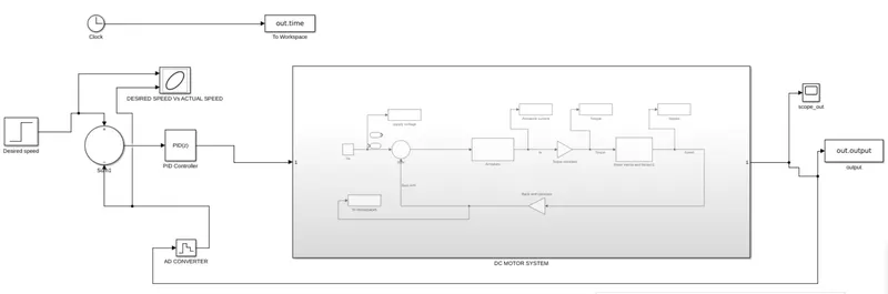
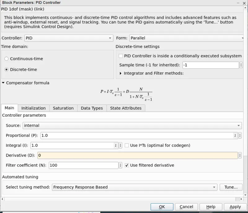
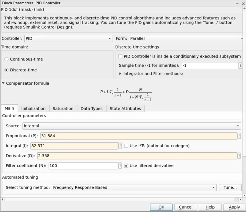
The DC motor model is converted in to subsystem and which is fed in to a PID Controller. The PID Controller is start with an intial condition as Kp=1,Kd=1 and Ki=0. For obtain the control design objectives, we tune the system. The Kp,Kd and Ki becomes 31.58,82.317 and 2.358 respectively.
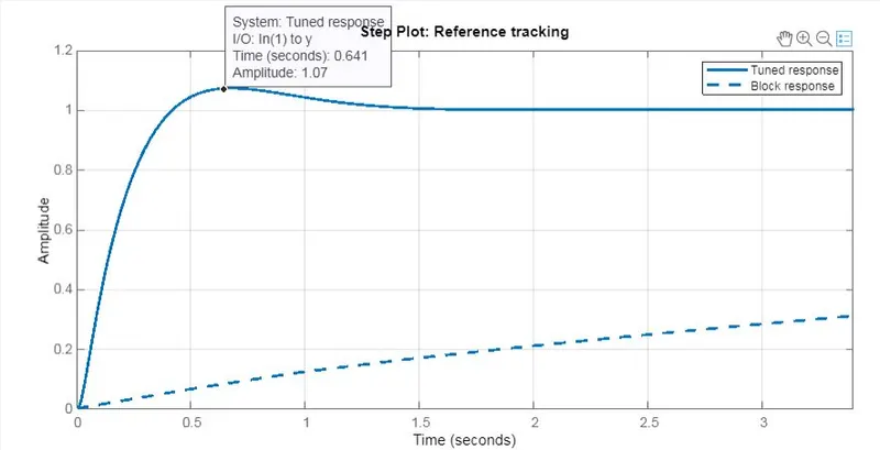
PLOT FOR OVERSHOOT LESS THAN 5%
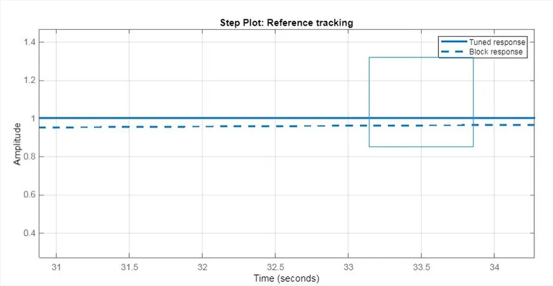
PLOT FOR STEADY STATE ERROR LESS THAN 1%
OBTAINED PLOT AFTER OPTIMUM TUNING
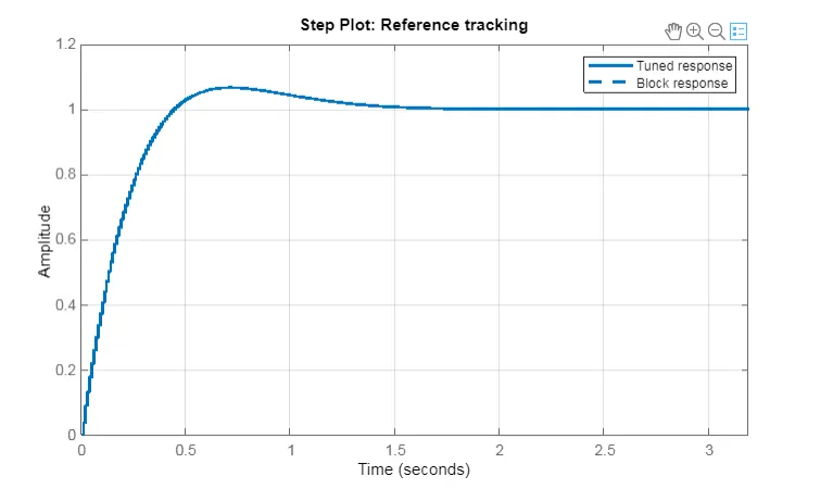
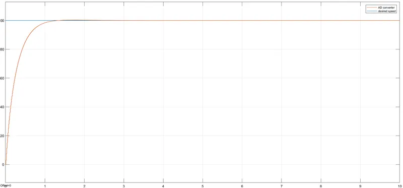
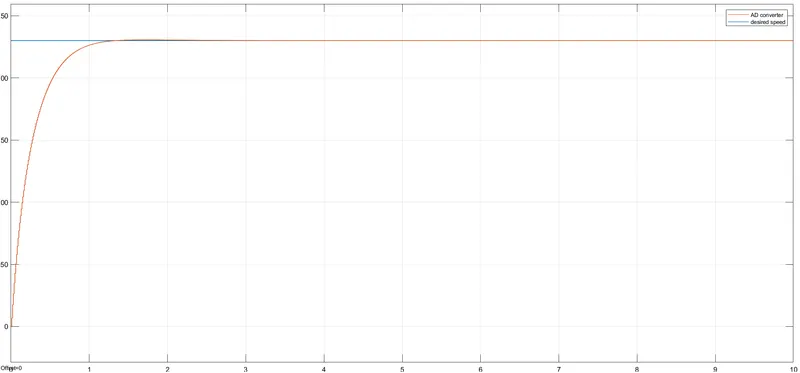
The system has been tuned with PID controller. So the stability plot of a dynamic system is obtained from the output workspace. The speed of DC motor is maintained at different voltages(100 V 220 V)
DESIRED SPEED PLOT OF MOTOR AT 100 V
DESIRED SPEED PLOT OF MOTOR AT 200V
PROBLEM CONCLUSION
Designed a DC Motor system with DC motor parameters.PID control system is introduced to regulate the speed of DC Motor.The overshoot value and steady state errors are increased with increase in supply voltage. Better response is obtained at lower supply voltage cases. Below 2 second setting time is obtained at lower supply voltage.Below 5% of overshoot is obtained at lower supply voltage. Below 1% of steady state error is obtained at lower supply voltage. The spped of DC motor is regulated with different supply voltage(100 V & 230 V).