Week 12- Final project
FINAL PROJECT:DEVELOPMENT OF A DOOR TRIM PANEL
INPUT SURFACES:
-CLASS A surfaces of the DOOR ARM REST, MAP POCKET, BOTTLE HOLDER and LOWER SUBSTRATE.
-MASTER SECTION FOR ATTACHMENT CREATION
-PUSH PIN CLIPS TO ATTACH ON DOG HOUSE FOR FITMENT PURPOSE
DOOR TRIM PANEL OF AN AUTOMOBILE:
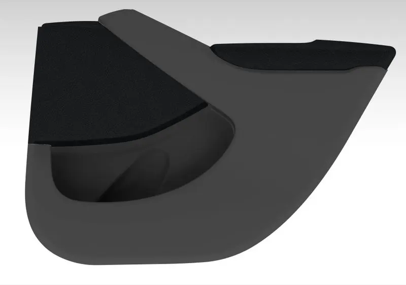
The door trims are the interior parts that contain the most controls and decorative parts. As such, there is a necessity for balancing gap between parts, as well as an overall sense of unity between the numerous parts.
OBJECTIVE:Creation of door trim panel using the given CLASS A surface as reference and the master section given is to be used to find out the nominal thickness of different parts.Then creating B side attachment features for the purpose of fitting different parts together and also for the the fitment of whole door trim part to any adjacent part.Any B side attachment that is to be created should be created by following the design guidelines followed in industries.
- To carry out repair works on given CLASS A surface if any needed
- performing draft analysis on the CLASS A surface output
- Creation of tooling axis for each component
- Conversion from A to B for each parts
- Creating CLASS C surface with necessary draft and to obtain the final closed surface for each body
- To obtain solid component using closed surface tool
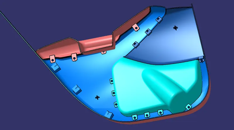
- Creation of B side features like flanges,heat stakes,dog houses and four way locators
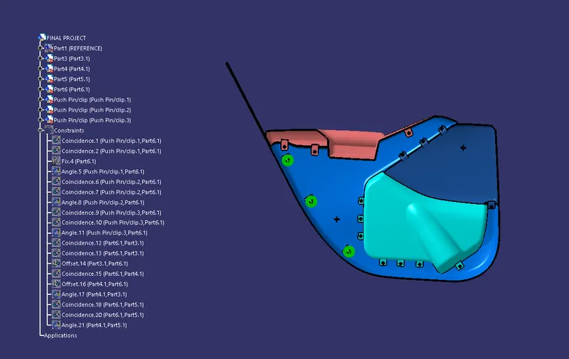
- Assembling parts together using assembly constraints in the end
APPROACH:TOP DOWN APPROACH
TOP DOWN approach is the method of creating an assembly by creating parts inside assembly workbench in their respective working position only, which eases the later assembling of parts and also the locating of B side features with respect to one another.Using this method the input surface is inserted to the assembly workbench and its each surface is added as different parts to carry out works on each seperately.
CLASS A SURFACE REPAIR:
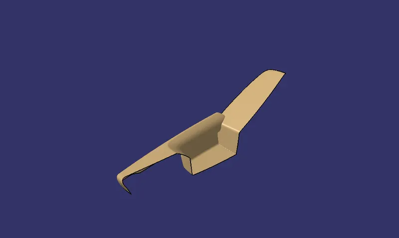
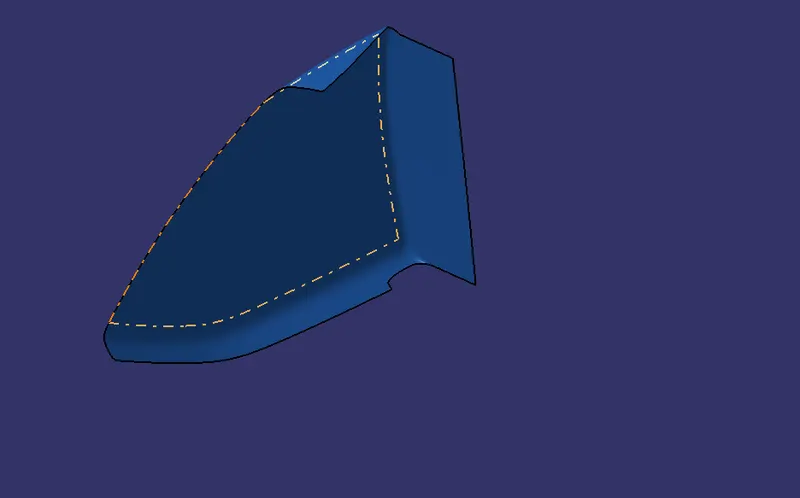
Class A surface is nothing but the surfaces that are visible in an automobile which is of highest quality and efficinecy and also of aesthetically superior finish.The repair is carried out on each parts if any needed using split,multi section and blend tools.Then after repair CLASS A surface output is obtained for each part.
DOOR ARM REST:
MAP POCKET:
BOTTLE HOLDER:
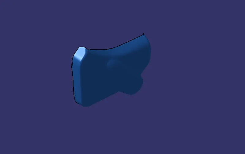
LOWER SUBSTARTE:

TOOLING DIRECTION CREATION:
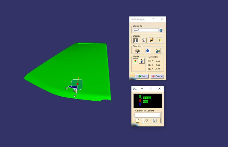
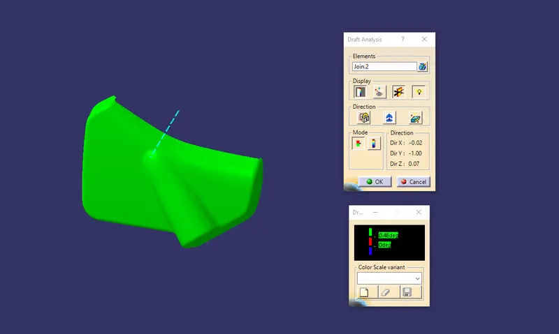
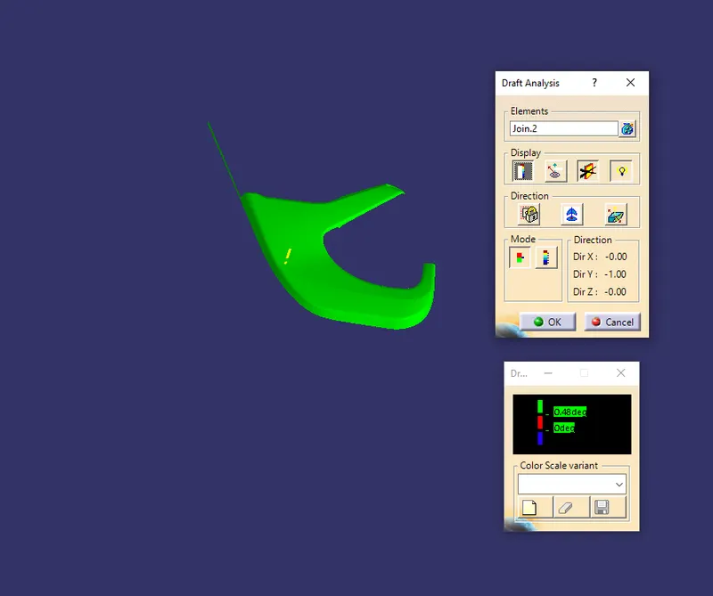
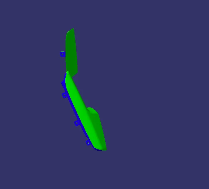
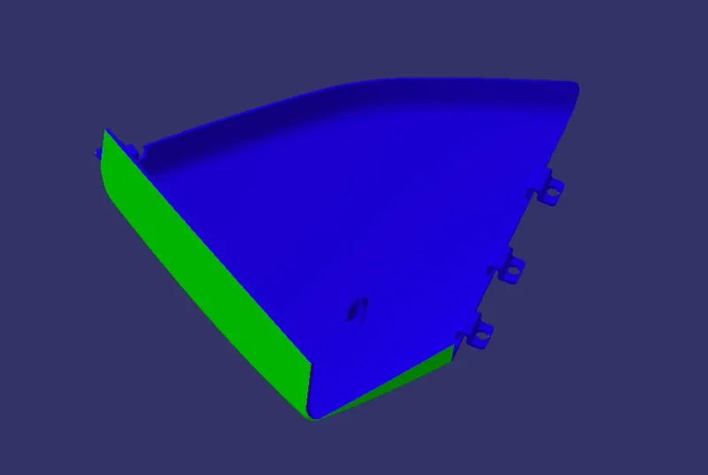
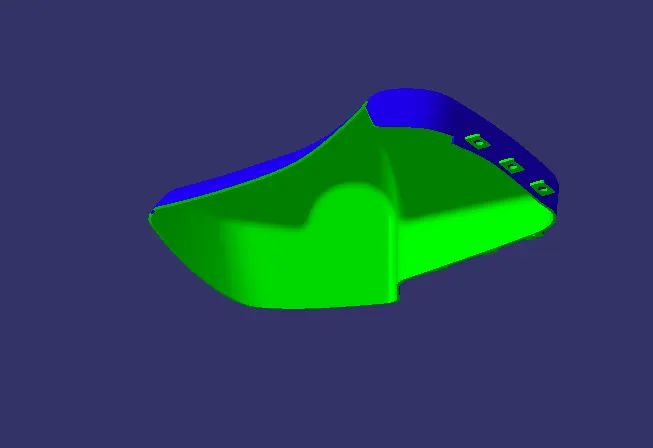
Tooling direction for each part is creaṭed using NORMAL TO SURFACE method.In nomral to surface mehtod ,a point is created on the surface and then a line is created in appropriate direction using point-direction option.using this line draft analysis is carried out for the output of the class a surface and adjustments in the line direction is carried out if needed by fixing the compass direction and changing the line direction to compass direction
Tooling axis and draft analysis of CLASS A surface:
DOOR ARM REST:
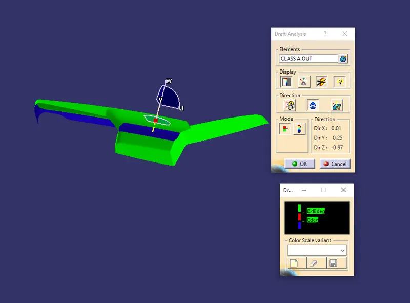
Because of the undercuts present on the door arm rest it is not possiblr to get perfect draft analysis along any tool direction so most appropriate direction is opted.
MAP POCKET:
BOTTLE HOLDER:
LOWER SUBSTRATE:
CLASS B SURFACE CREATION:
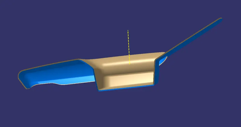
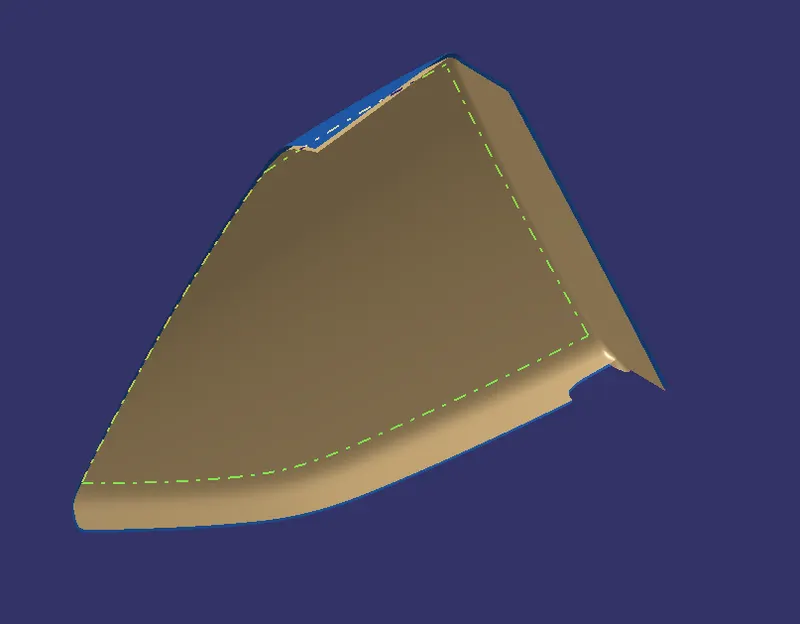
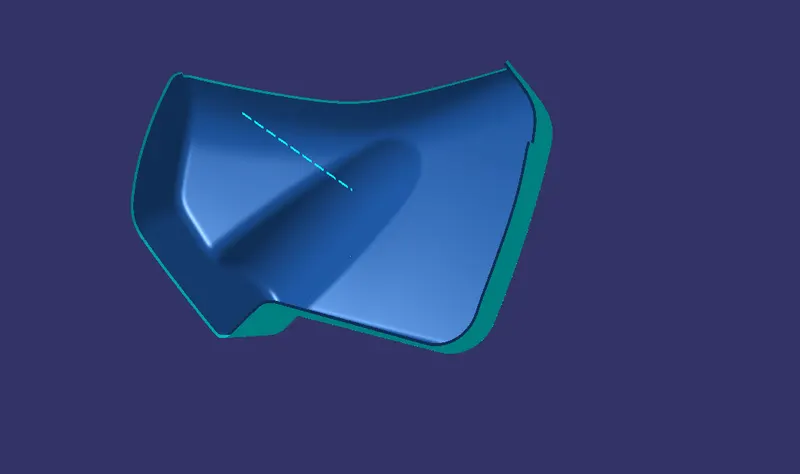
Class B surface for each part is created by offseting the CLASS A surface in the required direction to a distance of 2.5mm.Then on the CLASS B surface if any sharp edges are present it is repaired with the help of multi-section and split tools.And B surface is later extrapolated a little bit on required portions to ensure the intersection between B surface and C surface.
DOOR ARM REST:
MAP POCKET:
BOTTLE HOLDER:
LOWER SUBSTRATE:
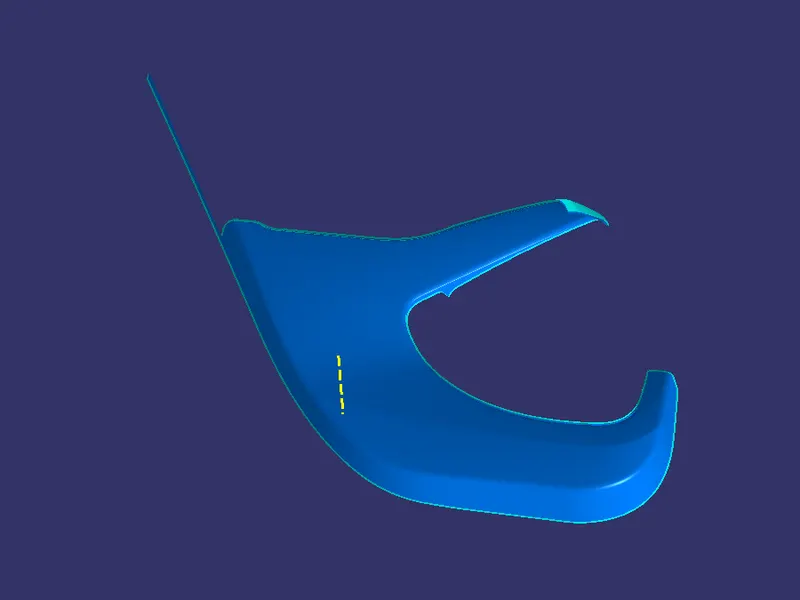
CLASS C SURFACE CREATION:
For the creation of CLASS C surface the input is the output of the CLASS A surface of each part respectievely.CLASS C surface is created by creating a single boundary or part by part boundaries and then using sweep with reference surface with necessary draft angle also provided.For those parts where C surface is created part by part,later those C surface is trimmed together and created a single C surface
DOOR ARM REST:

MAP POCKET:
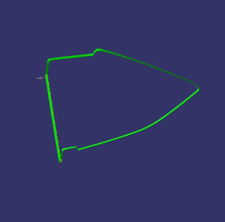
BOTTLE HOLDER:
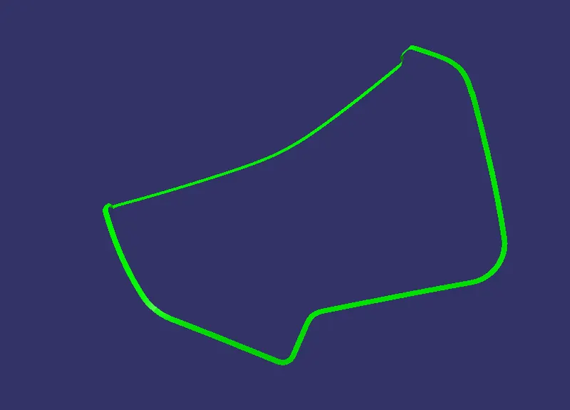
LOWER SUBSTRATE:
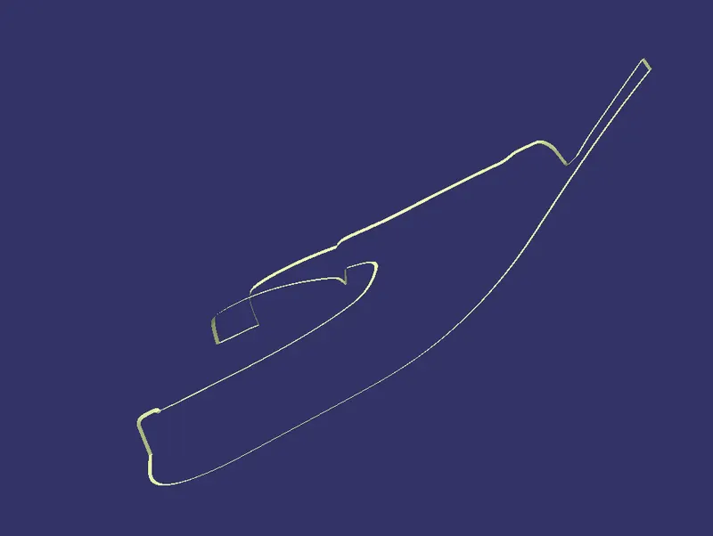
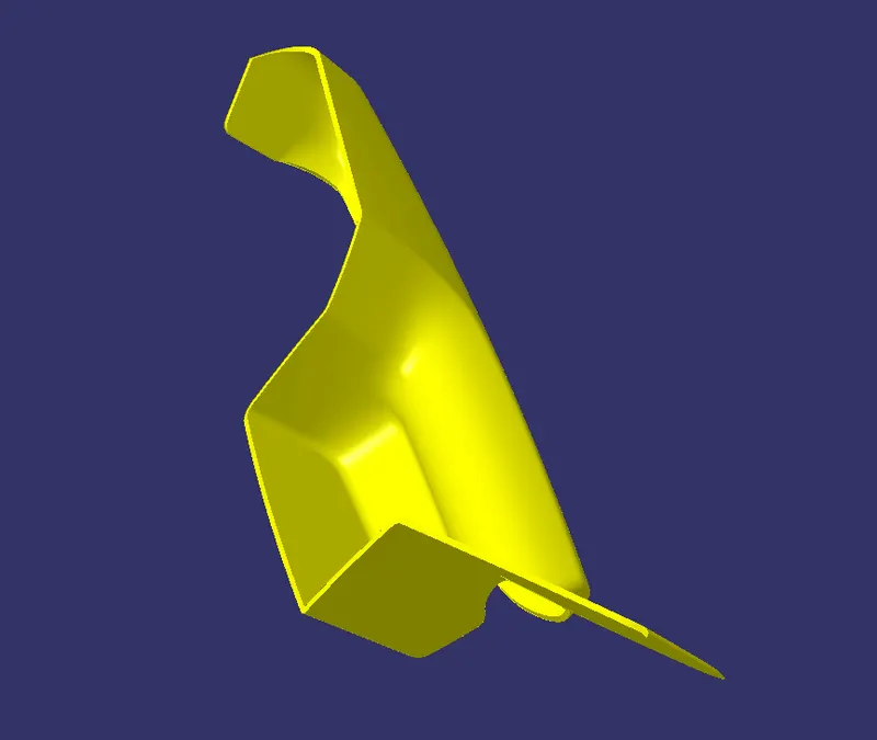
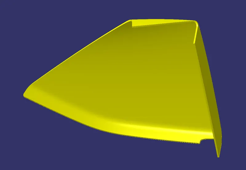
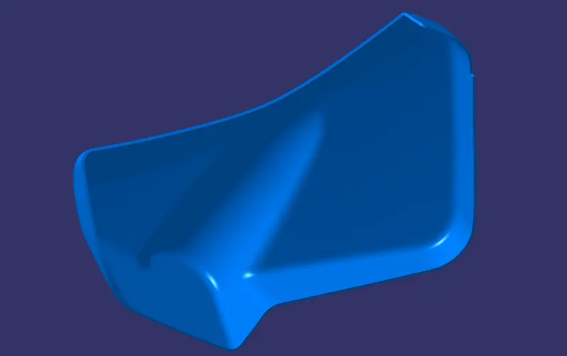
CLOSE SURFACE CREATION
Close surface is craeted using the outputs of CLASS A,B,C surfaces .CLASS C surface is trimmed together with CLASS B Surface and then CLASS A surface .Hence we obtain the final close surface body on which solid component can be created using close surface tool.
DOOR ARM REST:
MAP POCKET:
BOTTLE HOLDER:
LOWER SUBSTRATE:
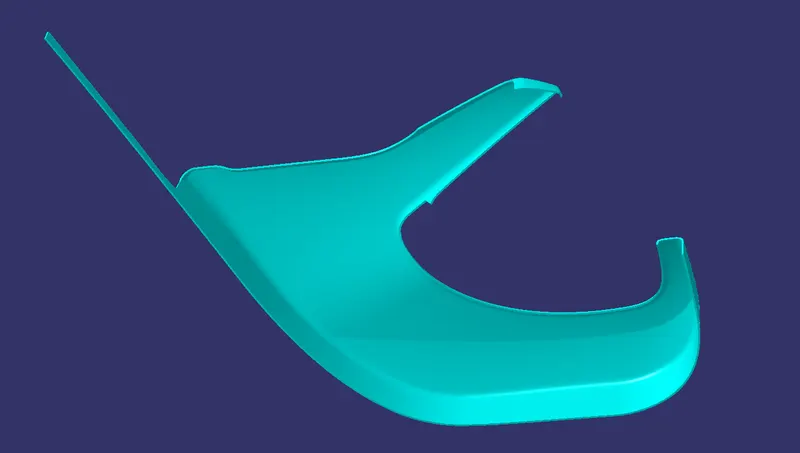
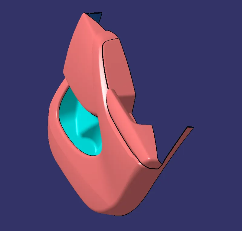
Now using close surface tool each part is made into solid component on which we further create B side attachments.
COMPLETE SOLID COMPONENT:
B SIDE ATTACHMENT FEATURES:
On B side we create attachment features like dog houses,flanges and heat stakes and also four way locators.
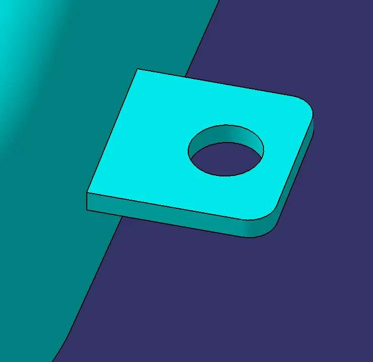
FLANGES:
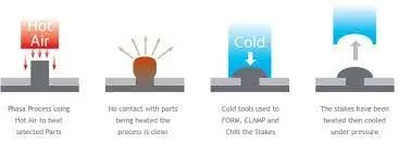
Flanges are created on parts other than lower substrate so that on lower substrate heat stakes can be created and permanent fitment between bodies can be achieved using Heat Staking.It is a pulsed-heat process to join two or more parts out of which one at least is made of plastic. The process is to deform the plastic material using heat and force at a set process time. The bond is made by partially de-forming the plastic part in order to fix the other.
- The flanges in different parts are created in different shape inorder to ease the fitment and locating of heatstakes form the lower substrate.
- The thickness of heatstake is taken similar to the nominal plastic thickness and holes are placed accordingly so that heastales from lower substrate can be easily go through the hole.
- The hole diameter is kept 8mm because the outer diameter of heat stakes is 7mm
- Fillets were given to sharp edges accordingly and also at some part draft angle is also provided
- FLANGES are placed by creating points on surfaces randomly where it felt needed and the orientation of flanges controlled using TRANSLATION and ROTATION tools
Flanges on door arm rest:
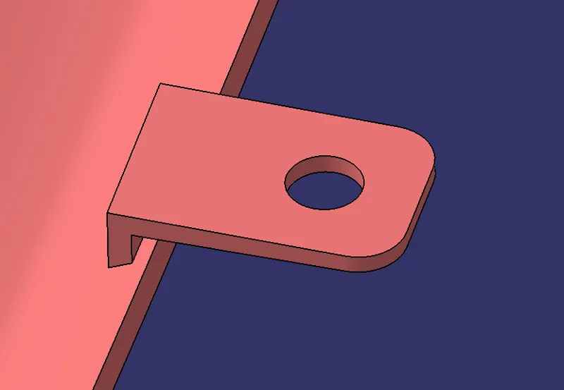
Flanges on map pocket:
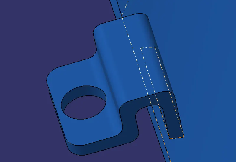
Flanges on bottle holder:
HEAT STAKES:
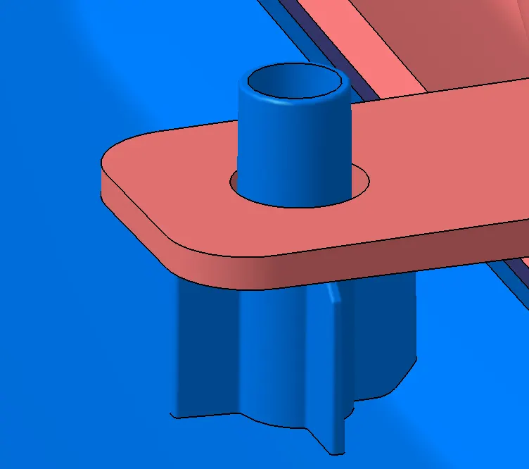
- Heat stakes are created with an outer dia. of 7mm so that it will easily pass through the respective flange hole whose dia. is 8mm and the inner dia. of the heat stakes is provided as 5mm
- Ribs are created around heat stakes for supporting purpose which will serve the supporting purpose for flanges also
- The design of ribs are made in way which the adjacent flange should rest on that so that it will support the flange also
- The location of flanges decides the location of heatstakes so that it will pass through the hole perfectly.
- we can project the centre point of the respective flanges to the lower substrate surface or we can manually locate the heat stakes by creating a point and adjusting the point location
- heat stake bodies are copied and translated to desired locations and required changes are made in the body so that it will become the resting surface of flanges
DOG HOUSE:
Dog houses are created with dimesnions as oer the guidelines
- the dimensions are like the following
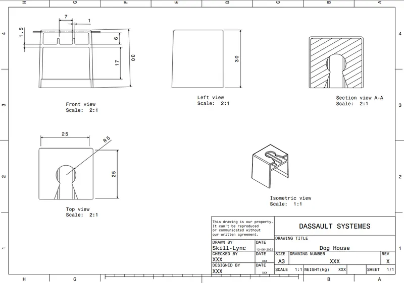
- The top hole dia. is reduced considering the push pin diameter
- Three dog houses are created and translated to desired locations
- Required draft angle and fillets are provided to dog house
FOUR WAY LOCATORS:
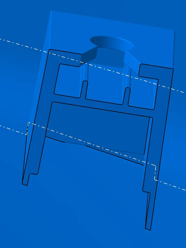
Four way locators serve the purpose of locators as well as they restrict the DOF of the component when attached to other part by restricting translations as well as rotations
- four way locator is created in 15x15 measurement and a suitable pad height is also given
- Draft angle is privided on the vertical faces of the locators
- chamfer is applied on the top edges
- Fillets are also applied on the sharp edges
- For a compnent two four way locators is enough to restrict its DOF s so two is created in desired locations

B side attachments:
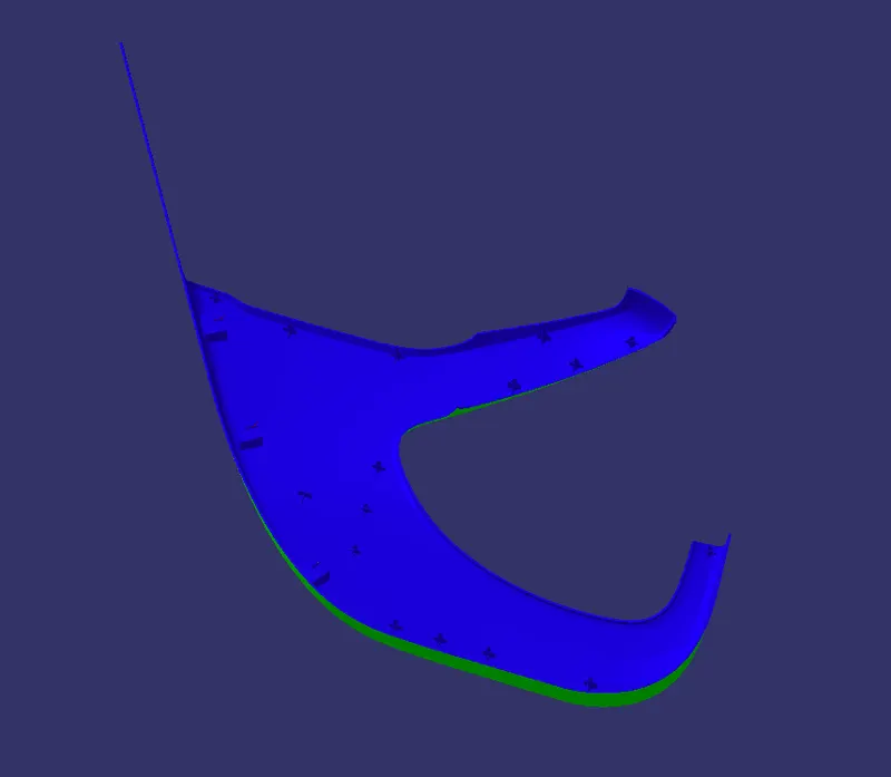
FINAL DRAFT ANALYSIS OF EACH COMPONENT:
ASSEMBLING OF PARTS TOGETHER;
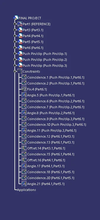
- The final component is assembled with respect to each other and restricted every degree of freedoms.
- Lower substrate is fixed and other parts DOF s arrested with respect to that
- DOF s arrested using coincidence,angle and offset constraints
- Push pin is inserted into the assembly and placed on top of dog house and the its DOF s are arrested there so that it is fixed there.
RESULT:
Final component of door trim panel is obtained after following the above explained steps
- Materials used to manufacture the parts can be selected depending on the requirements
- For door trims usually POLY PROPYLENE(PP),POLY ETHYLENE(PE),ACRYLONITRILE BUTADIENE STYRENE(ABS)
- Nowadays combination of PP and PE is also used to obtain the qualities of both