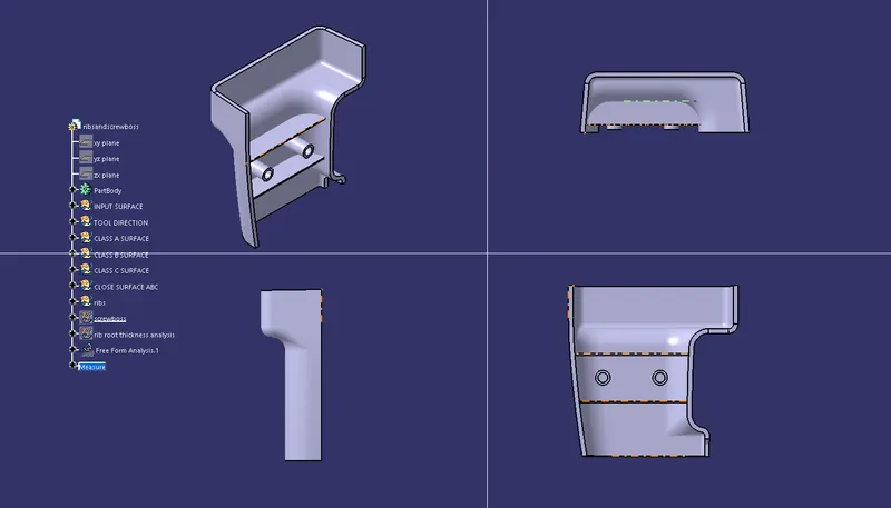
Week 10 - Challenge 1- Attachment Feature Creation (Ribs & Screw Boss)
ATTACHMENT FEATURE CREATION:RIBS AND SCREWBOSS
AIM:To create b-side attachment featues like ribs and screwboss by creating a model from given class-A surface.our first requirement is to create a model using A-B conversion
STEP 1:CLASS A SURFACE connectivity check-Input surface is given CLASS-A surface and we perform a connectivity check using join command on it to ensure the connectivity of the surface and to check whether any sharp edges are there to be repaired.by using join command we found out that the surface is ready and good to make a solid model out of it
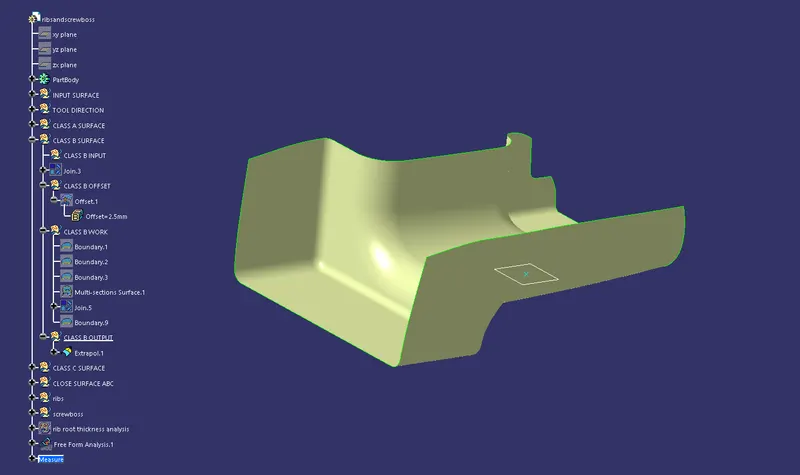
STEP 2:CLASS-B SURFACE CREATION- From the given CLASS A surface a CLASS B surface is created by using offset tool to our required 2.5mm distance.Then a repairing work is carried out on parts that cannot be offsteted using multisection command and then made sure that there is no need for more repair by checking whether there is any sharp edges or not.Then we extrapolate the B surface a little bit to ensure proper trimming once after the C surface creation
STEP 3:CLASS C SURFACE CREATION- For class C surface creation the input is class A surface and by creating seperate boundaries and sweep,step by step we create the complete CLASS C surface.And trim them together to create a single CLASS C surface but at some parts trimming is not possible where split command is used 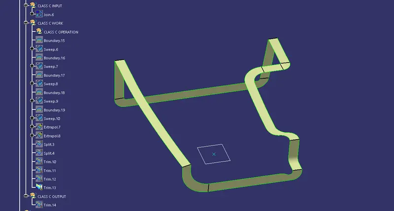
STEP 4:TRIMMING OF CLASS A,B,C
Now we trim both class B&C together at first and then we join it with the class A surface to create the required shape and the output is as follows
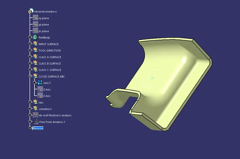
STEP 5:CREATING SOLID BODY USING CLOSE SURFACE
STEP 6:CREATION OF RIBS
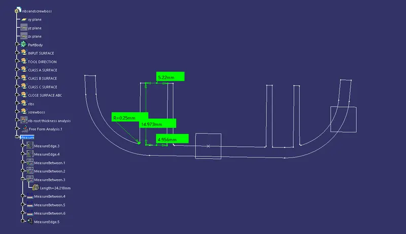
For creating a rib,we insert a geometrical set and then create a line on the surface of the part body by offseting a particular plane to the point.This line is then padded using thick command within the pad option to a height of 12.5mm and a thickness of 1mm is given as neutral fibre(the dimesions chosen as the given guidelines as attached as following)
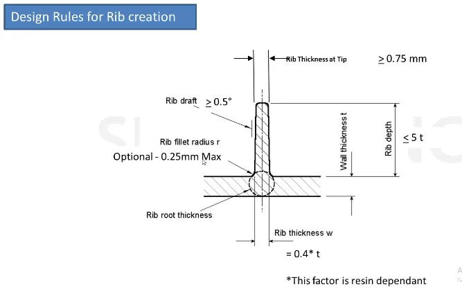
for this case t=2.5,so the calculations are made accordingly and then draft is applied by keeping the bottom face of the rib as the neutral face
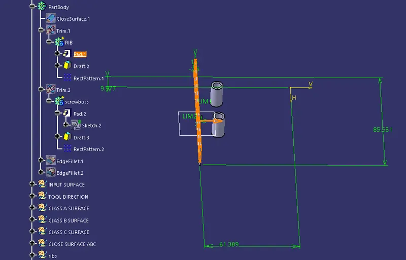
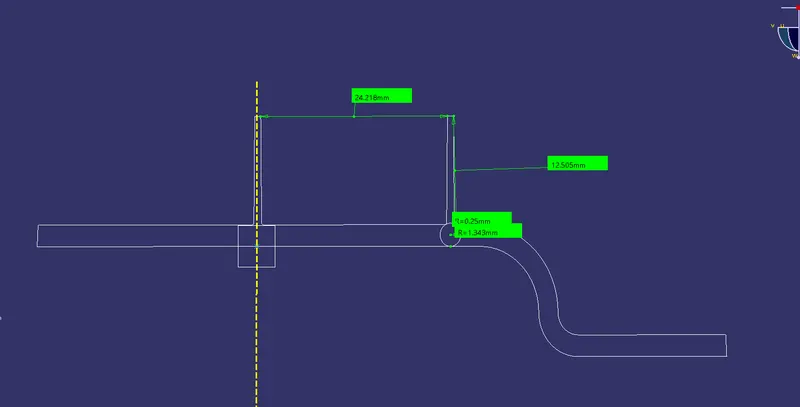
and using rectangular pattern created another rib at a particular distance as it is in the desired picture given.Intentionally the length of the rib is kept extra to use union trim and create a single body afterwards and union trim between the rib body and the partbody is applied.
STEP 7:CREATION OF SCREWBOSS
For creating screwboss the same procedure is followed as for the ribs but the measurements of the parts is taken accordingly to the guidelines provided for the creation of the screwboss as per following;
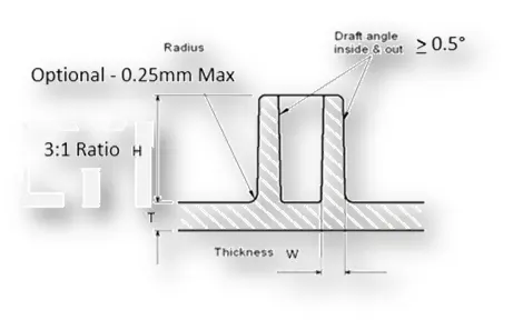
The inner diameter is taken as 5mm and the outer diameter is taken a 8mm so the height is taken as 15mm according to the 3:1 ratio providedand a darft angle of .5 is provided keeping the top face as neutral face.using rectangular pattern replicate the screwboss in a dsired position and and union trim it with the part body.
STEP 8:DRAFT ANALYSIS
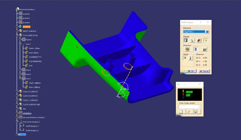
Draft analysis for the final boddy is carried out and class A surface has positive draft and class C surface is found to have a small undercut.
The tooling axis is created by means of both bisecting method and normal to surface method.preferably normal to surface method gave the best draft analysis and it is chosen as the tooling axis
DIFFERENT VIEWS OF THE COMPONENT: