Week 8 - Challenge 2 - Switch Bezel Design
AIM: To create a switch bezel model using the given CLASS A surface.
STEP 1:Ensure the connectivity of the given CLASS A surface by using the join command
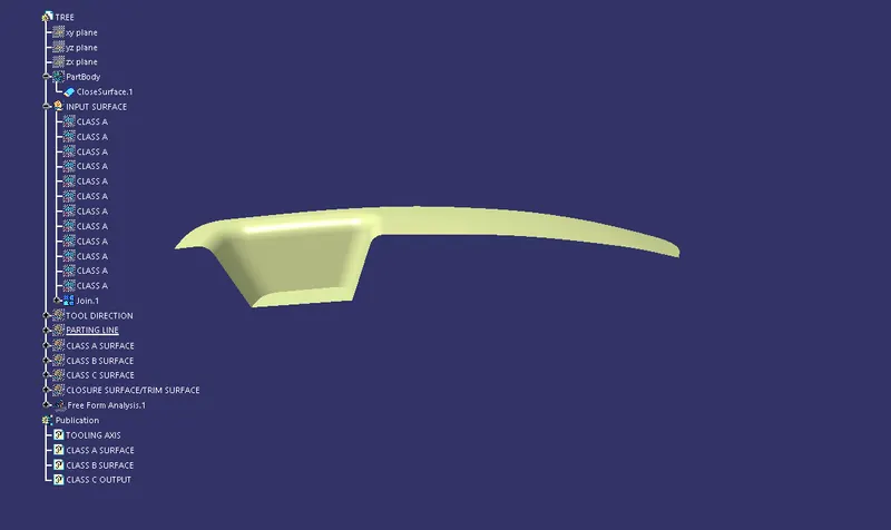
The given CLASS A surface is made a single part using the join command and now we must create a tooling direction to meet the requirments of draft analysis
STEP 2:Tooling axis creation
Tooling axis is created using trail and error method by carrying out darft analysis on CLASS A surface and changing the compass direction accordingly a suitable direction is found out
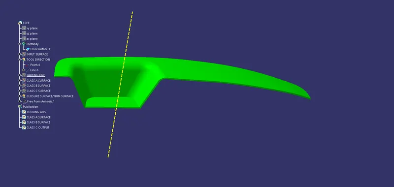
Tooling direction is created by extracting the base surface to create a point there and by isolating the point and then removed the extract.Then on the point created a line using point-direction option and made it in the Z direction primarily and carried out the draft analysis.Using the darft analysis changed the compass diection to find which direction gives complete positive draft on CLASS A surface.The obtained direction is locked on the compass and then made another line in the compass direction which is our tooling direction
STEP 3:CLASS B Surface creation
Input for the CLASS B surface creation is the output of the surface A which is a together joined single part of CLASS A surface
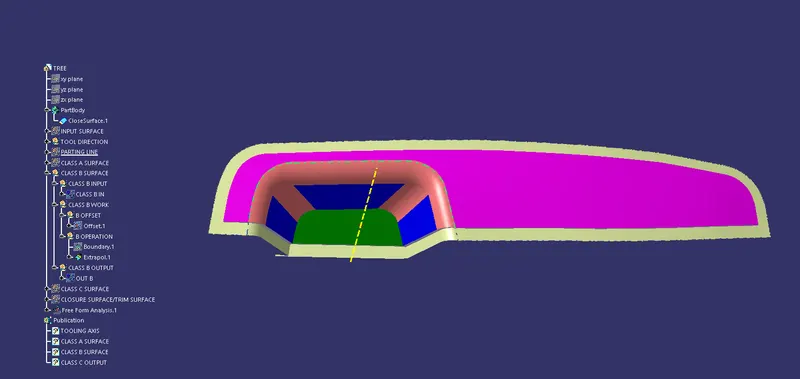
The input surace of CLASS B is offseted to the desired 2.5mm distance and created a boundary there for the B offset surface which is needed to create an extrapolated surface that is required for us to carry out the trim operation after creating the C surface.The boundary is extrapolated using curvature continuity to a 10mm ditance to obtain the CLASS B surface and then whole surface is joined using join command to create the CLASS B output surface
STEP 4:creation of CLASS C surface
The input for the CLASS C surface creation is output of both the CLASS A and CLASS B surfaces.
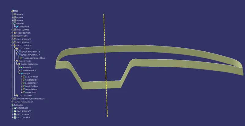
And then the class a surface is selected and a boundary is created.Then the boundary made smooth using curve-smooth tool by selecting the curvature option and that curve-smooth boundary is selected to apply the sweep using the draft direction
STEP 5:Trimming the components to obtain the final structure
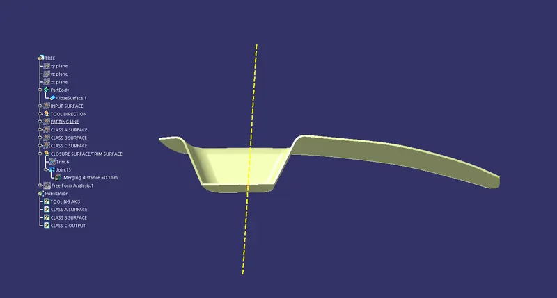
Trimming the surface C using surface B and then joining them together with surface A gives us the required final surface structure and then proceed to part body to make it a solid using close surface option
STEP 6:Final draft analysis
A final product draft analysis is carried out along the already made tooling direction.We may not obtain the desired draft analysis,Then required tooling axis direction changes are made in order to make it a positive draft
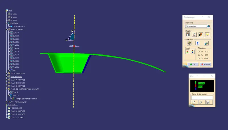
darft analysis of CLASS A surface
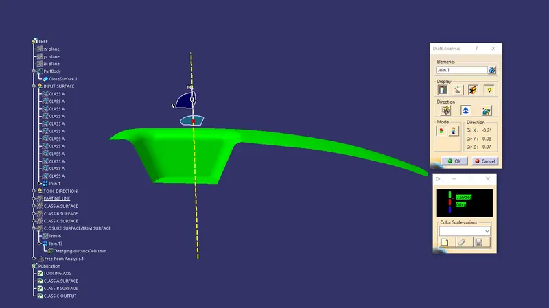
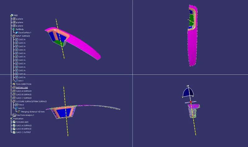
Different views of solid part