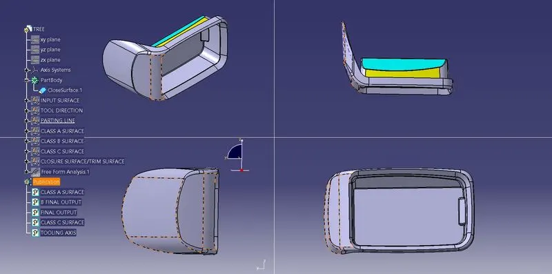
Week 8 - Challenge 3 - Coin Holder Design
AIM:
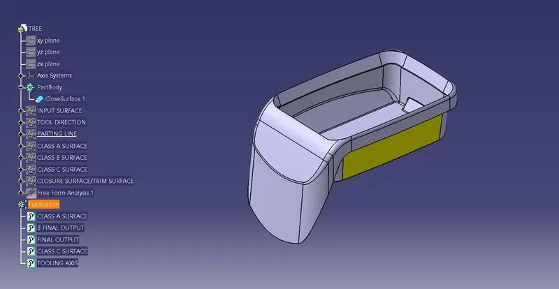
Create the Coin Holder Plastic component through the given Class-A surface.To begin with we check the connectivity of the given CLASS A surface
STEP 1:Ensure the connectivity of the given CLASS A model using join command.here every given surface is selected and joined using join command
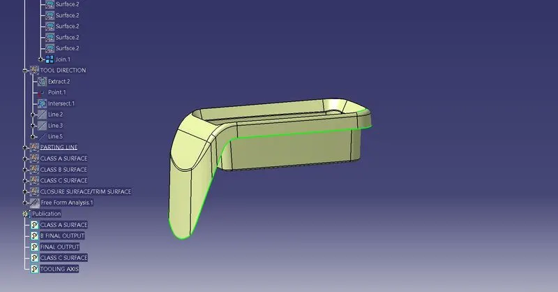
STEP 2:Tooling axis creation
Tooling axis can be created in different ways including bisecting method,normal to surface etc.Here in this case we created the tooling axis using the normal to surface method by extracting the base surface and creating a point on the extracted surface which we isolate from the extracted surface.Then we create a line which is in point direction and selected the direction as Y in this case beacuse it is the normal direction to the surface.through which we carried out a draft analysis to know whether we get a postivie draft along that and made changes to the axis using compass and positive draft direction is locked on the compass and then created a line along the compass direction.Which is our tooling axis
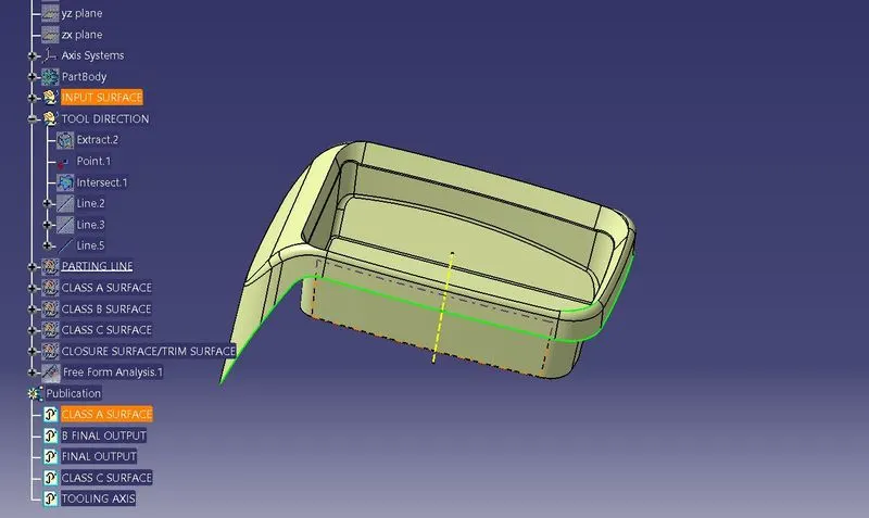
STEP 3:CLASS B surface creation
For the CLASS B surface creation we seperate the whole surface into different parts for the ease of working like SIDE WALL,TOP WALL,BASE,OUTER WALL and OUTER PART SLANDED FACE .And for each we extracted the particular faces and untrimmed it,then we extrapolated it to ensure the intersections to the adjacent sides before offseting it to a desired thickness distance of 2.5mm . Now we have every faces of CLASS A surface offseted to a desired 2.5mm distance inorder to make the CLASS B surface.
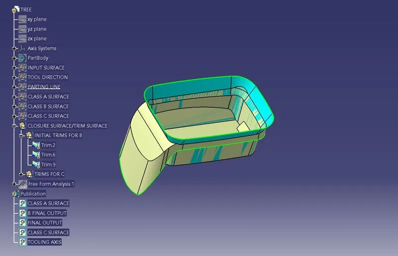
then we trim these together and apply the edge fillets in required positions accordingly selecting the radiuses by chekcing the radiuses of the given class a surface to make the final B output surface as attached below.
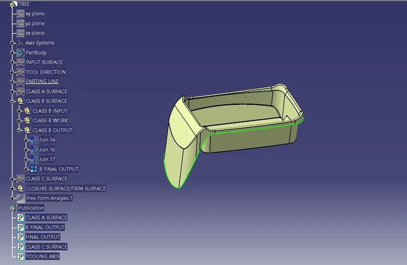
STEP 4:CLASS C surface creation
A boundary is created on the join of CLASS A surface to make the CLASS C surface.Then we smoothen the curve using CURVE-SMOOTH tool and sweep it using with reference surface option by selecting the extrapolated side surafce as reference and extarpolate it to 90 degree angle and A length oif 4mm to obtain the CLASS c surface
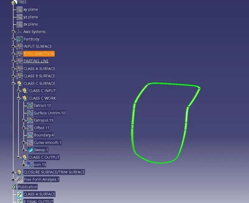
the required CLASS C surface is obtained
STEP 5:final trims
The obtained CLASS C surface is trimmed with the output of CLASS B surface and the joined with the CLASS A surface to obtain the final output surafce
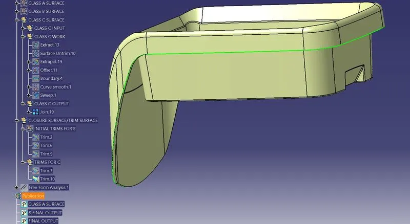
STEP 6:applying material to the surafce model using the closed surface tool
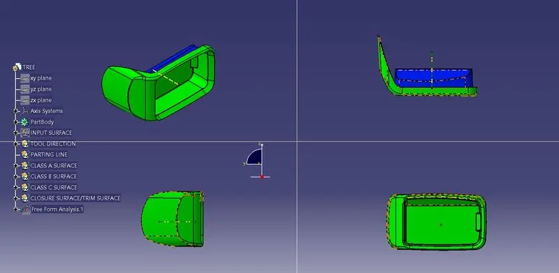
STEP 7:Draft analysis
Draft analysis is carried out along the tooling axis and found out that it is the correct tooling axis for the product
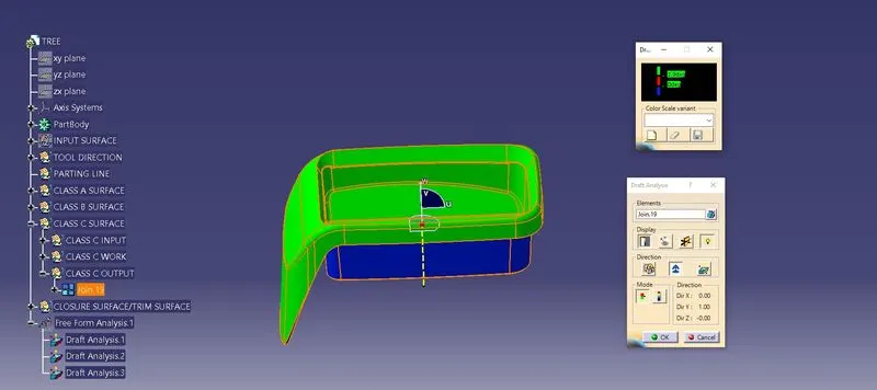
draft analysis for the class A surface also carried out while creating the tooling axis and made sure that it is positive draft
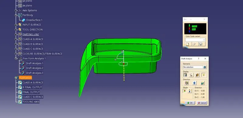
DIFFERENT VIEWS OF THE COMPONENT: