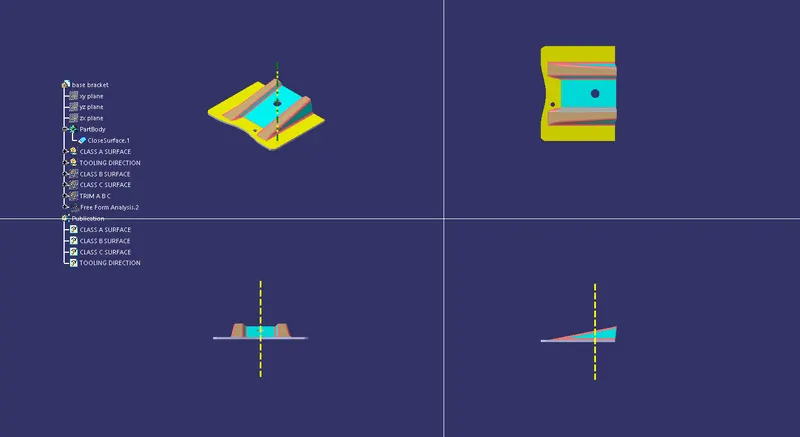
Week 8 - Challenge 1 - Base Bracket Design
AIM: Create the Base Bracket Plastic component through the given Class-A surface.For that to begin with i went on to check and ensure the connectivity of CLASS A surface
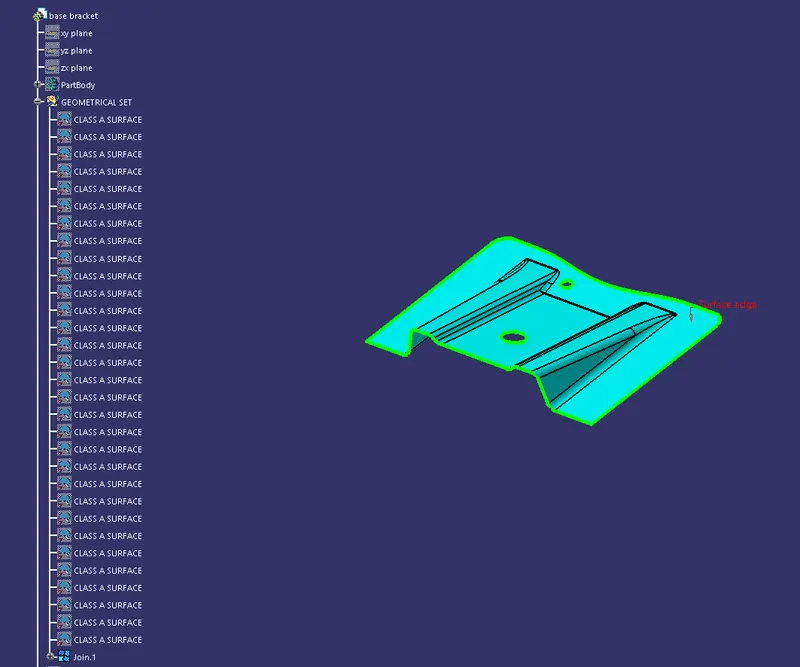
By using join command we can ensure whether the parts of surface A is joined and where are it's boundaries also.So here in our case there is an outer boundary and also two small inner circle boundaries,hence the check for connectivity is carried out and made sure the CLASS A surface is a single part
CLASS B surface creation:
After ensuring the connectivity we must make a CLASS B surface using the given CLASS A surface.
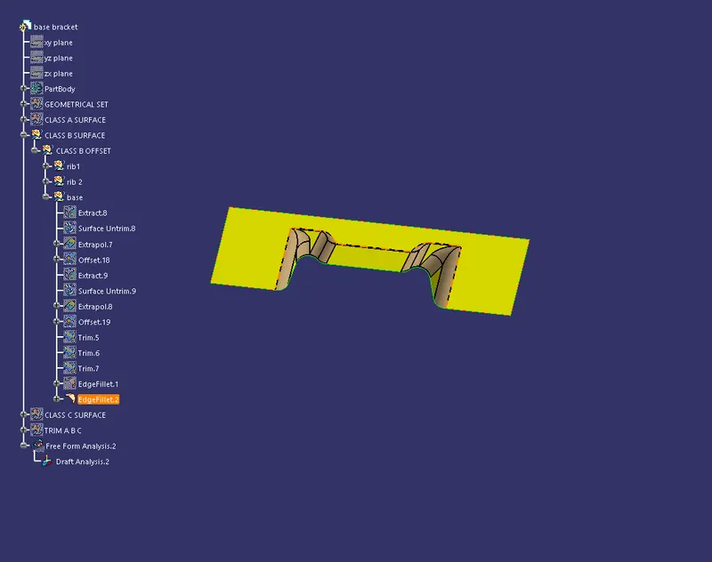
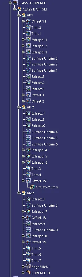
for the creation of CLASS B surface,we begin with the creation of the ribs by selecting the plane rib parts in the CLASS A surface and the extracted each of it,then using surface untrim achieved its base shapes,then extrapolated its edges to make sure they are intersecting to each other before carrying out trim.now we can use the trim tool to make them a single part and then we offset them to the desired thickness of 2.5mm distance to achieve the thickness.By using this method we can create both the ribs
Now we need other two surfaces extracted,surface untrimmed,extrapolated and offseted to a distance of 2.5. Now we have every component to make the base shape of CLASS B surface at a desired distance of 2.5.Now trim the inclined base with any of the ribs and then again carry out the trim with the other rib.Now finally make the trim with the base surface to achieve the final CLASS B surface shape
CLASS C surface creation:
Now we need a surface C between CLASS A&CLASS B.As mentioned earlier we have three boundaries in CLASS A surface
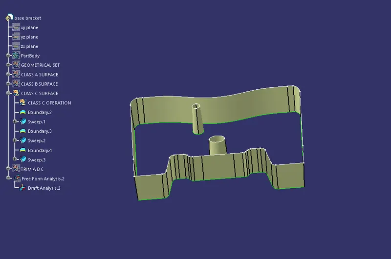
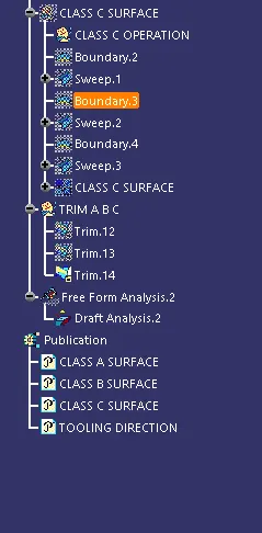
by selecting the CLASS A surface create boundaries for each of them one by one and then sweep each boundaries using the option with draft driection and give an angle of 3 degree as the draft angle by selecting the quadrants to which the angle should be given accordingly
CREATION OF TOOLING AXIS ALONG THE Z DIRECTION:
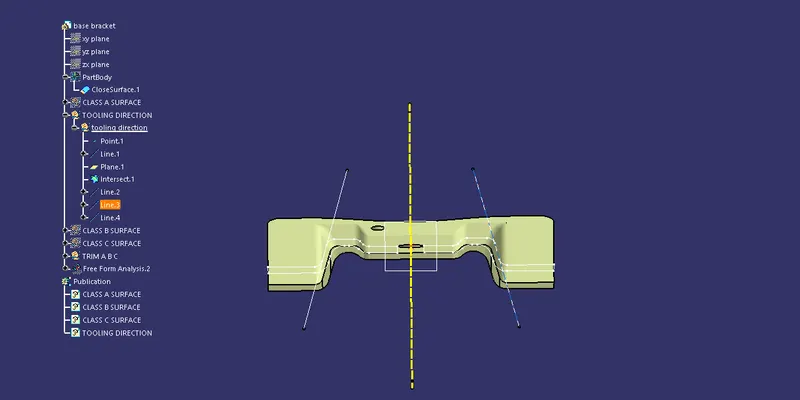
To create a tooling axis we need to perform the bisecting method to find the exact tooling axis for the product,the process of bisecting method is,
EXPLANATION ON BISECTING METHOD:
Bisecting method is basically use to find the proper tooling axis using the dummy tooling axis. In Bisecting method, bisecting line is used which either bisect the two line or it will show error which means the two lines are parallel to each other. In order to know whether the particular surface is toolable or not we intersect the surface with the respective plane and get a sketch which consist of two lines and with the help of bisecting line option we bisect the line which creates a line at the mid point of the two lines. Like wise we create tooling clearing axis for x and y which will be used to create the main tooling axis using the bisecting line option in in the line comand.
DRAFT ANALYSIS:
Draft analysis is carried ot to ensure the practicality of the tooling direction and it helps us to decide where the core and cavity side would come
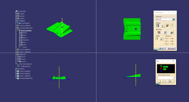
by doing the draft analysis we made sure that the product is fine to manufacture because the desired color code is achieved once after carrying out draft analysis as obtained in the abive screenshot
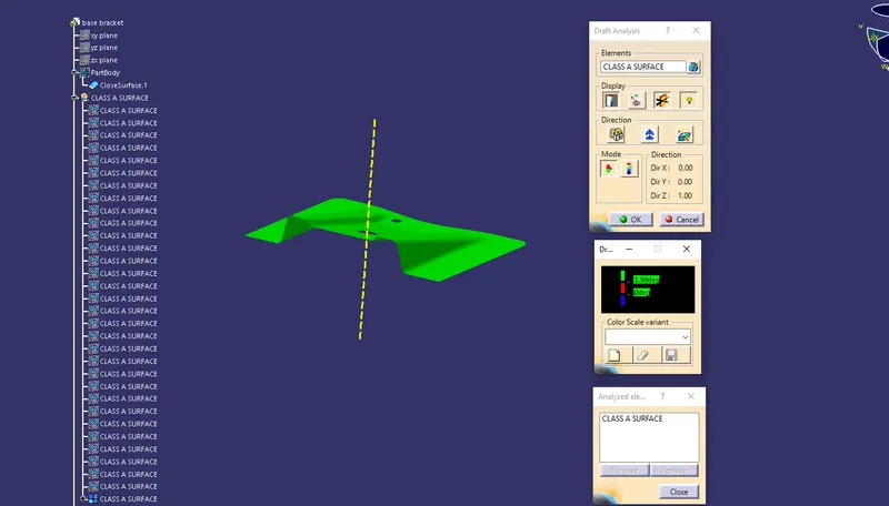
Draft analysis is carried out for given CLASS A surface also;
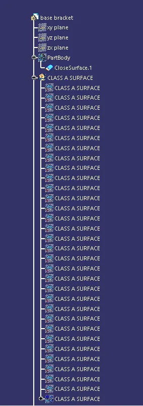
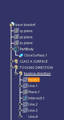
TREE STRUCTURE
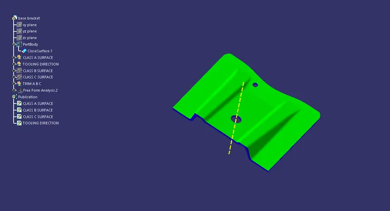
Screenshot of the solid model with the proper color code of the draft angle in various orientations ;