Week 12- Final project
Design and develop car door trim panel with B-side features meeting design criteria and manufacturability using CATIA V5
OBJECTIVE
Creation of CAD model for door trim panel considering following inputs as like in OEM and tier1 companies
- Class A surface
- Nominal thickness : Refer master sections
- Attachment strategy :
- Find a attachment strategy for the door panel complete work.
- Use Push pin with Dog house for Lower substrate – Door panel attachment
- Use heat stakes for part to part attachment
INTRODUCTION
The door trim panel is more than just an interior component; it is an essential component that combines aesthetics, functionality, and engineering. Its design displays a brand's dedication to quality and innovation, while also ensuring passenger safety, comfort, and satisfaction. The door trim panel is a key component of an automotive interior, that purpose both functional and aesthetic purposes. It is located on the interior side of the vehicle/car doors and serves as a bridge between the door's mechanical structure and the passenger surroundings. With increasing demand for customization, reducing weight, and advanced features, the design and manufacturing of door trim panels is advancing and pushing the boundaries of material science and automotive design.
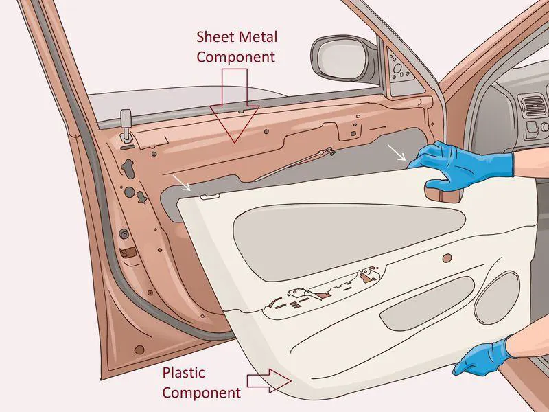
Key features to design and develop a Door Trim Panel are:
Class A Surface
Class A Surface include surface finish and ergonomic features. Aesthetic materials such as leather, fabric, or soft-touch polymers are used for a premium look. To enhance ergonomic features smooth and accessible designs for armrests, handles, and storage compartments like bottle holder are required.
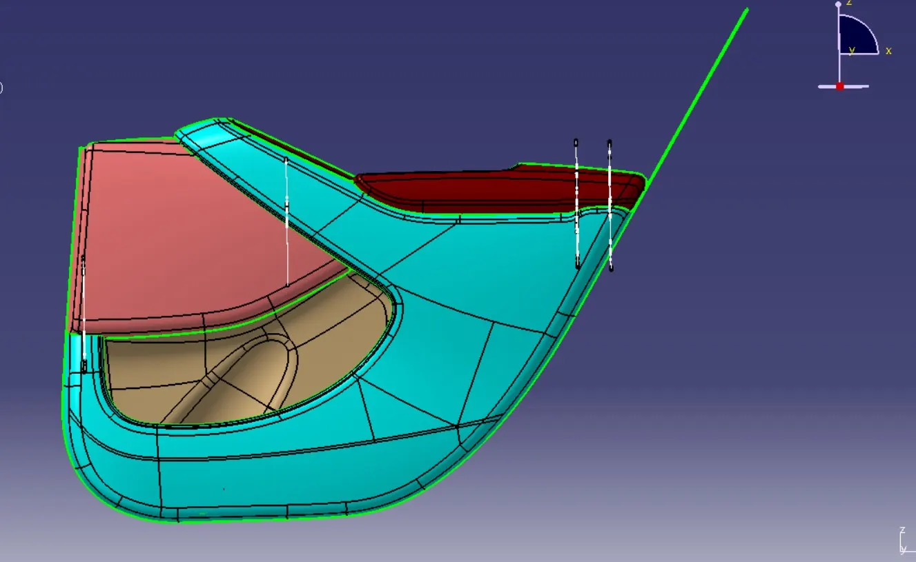
Class B Surface
Class B Surface, which is obtained by offsetting Class A Surface to the thickness of the component. Generally plastic component thickness are taken 2.5mm to 3mm. All attachment and engineering features are created on B Side Features to meet both functional and structural. Attachment features includes dog houses, pushpin clips, locators, and heat stakes to securely attach the panel to the door frame. For reinforcement: ribs and flanges are created to enhance structural rigidity.
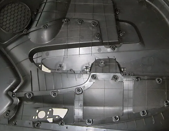
Door trim panels are often manufactured by injection molding process, which provides accurate detailing, structural uniformity, and cost-effective mass production. The Door trim panel material details must meet industry safety and performance standards. It is essential to use a high-quality, long-lasting material that can tolerate impact and wear. Materials such as ABS or PC-ABS blends are preferred because they provide good impact resistance, rigidity, and durability while being cost-effective. The material used for the door trim panel must also be compliant with environmental rules and meet flame resistance criteria.
Other common materials selected for door trim include:
- Polypropylene (PP) for lightweight and cost-effectiveness.
- Glass Fiber-Reinforced Plastics (GFRP) for added strength.
- Soft-touch Polymers and Polyurethane (PU) for enhanced user comfort.
DESIGN METHODOLOGY
Class A Surface of door trim panel are provided with master section for reference to create Class B Surface and B Side features.
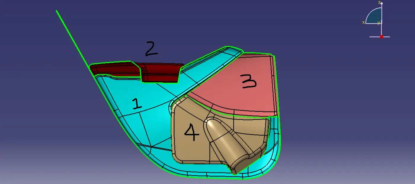
Components of door panel are:
- Lower Substrate
- Armrest
- Map Pocket
- Bottle Holder
Lower Substrate
Provides structural support and houses attachment points for other features like dog house, heat stake, locators etc.
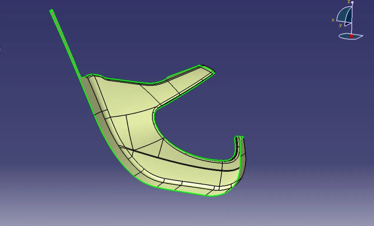
Class A Surface
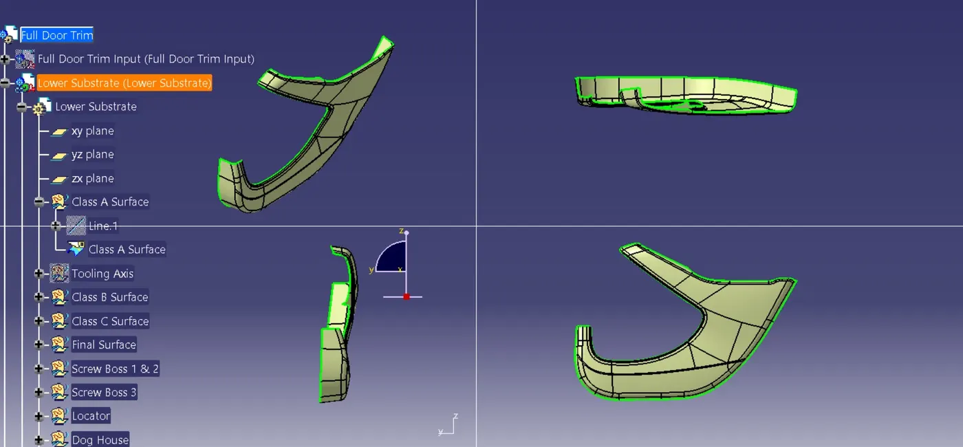
Tooling Axis
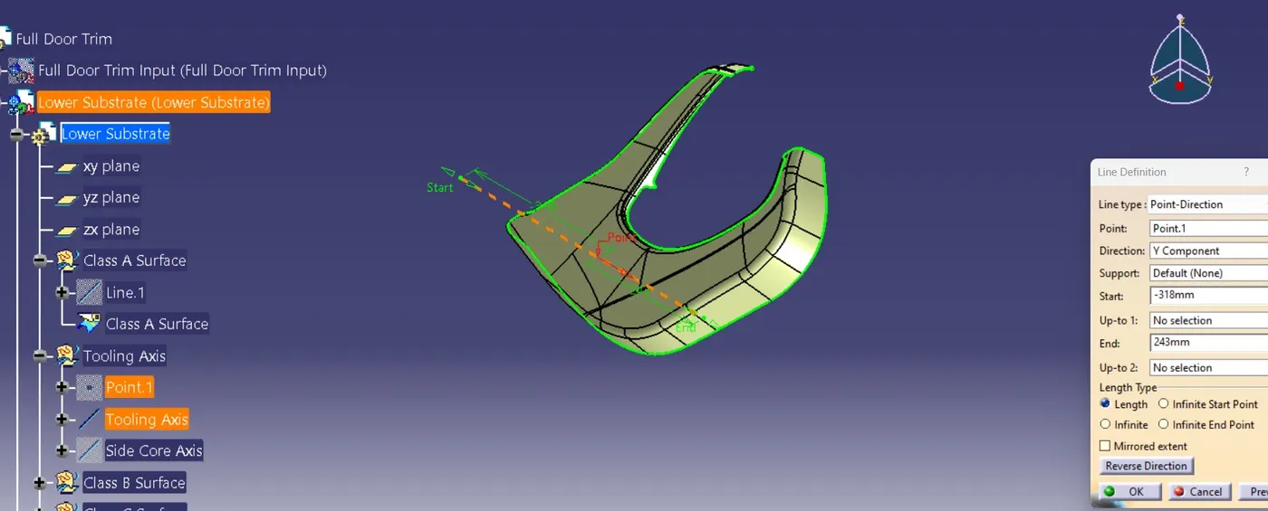
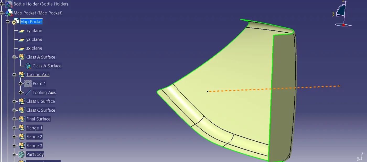
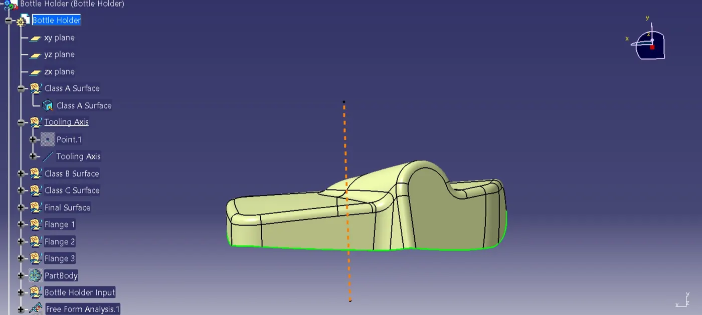
In injection molding, the Class A surface is examined initially to locate the tooling direction or axis that separates the molds from casting. Tooling direction is crucial in plastic product design as it determines direction at which the plastic part separates from the mold.
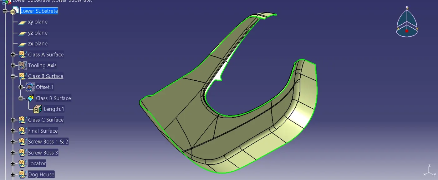
Class B Surface
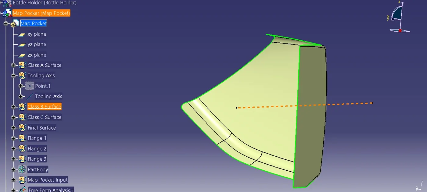
Class B Surface is obtained by offsetting the Class A Surface according to the thickness of the part. Here in this model 2.5mm thickness is taken.
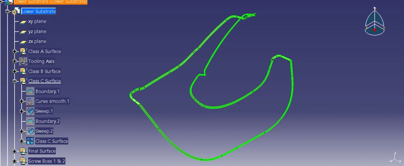
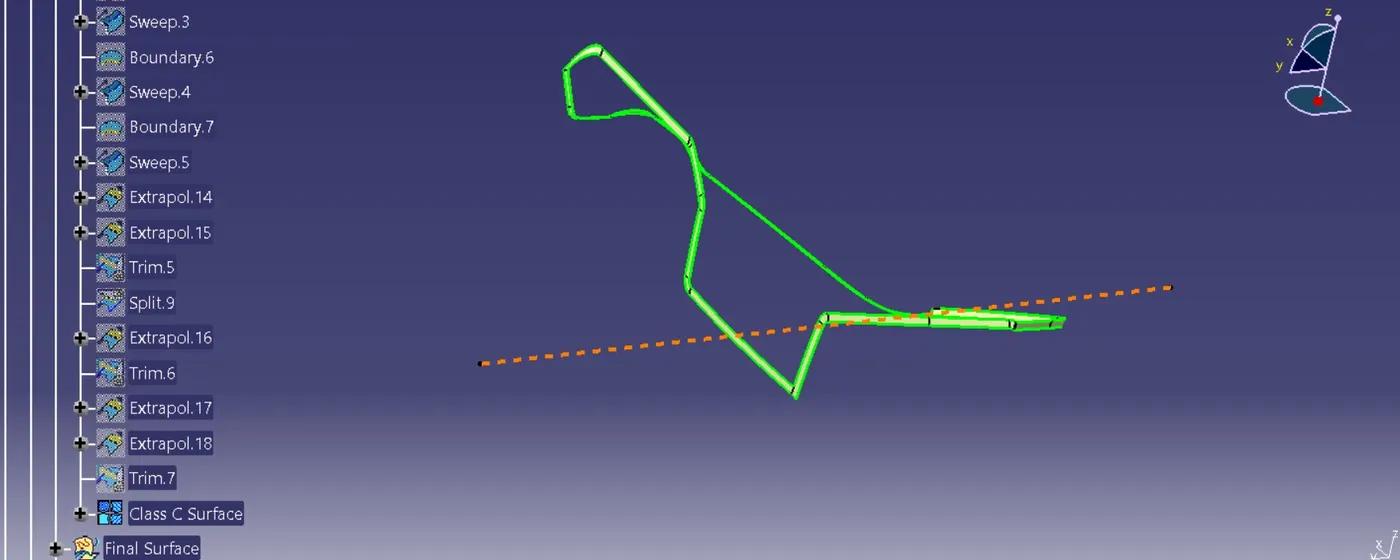
Class C Surface
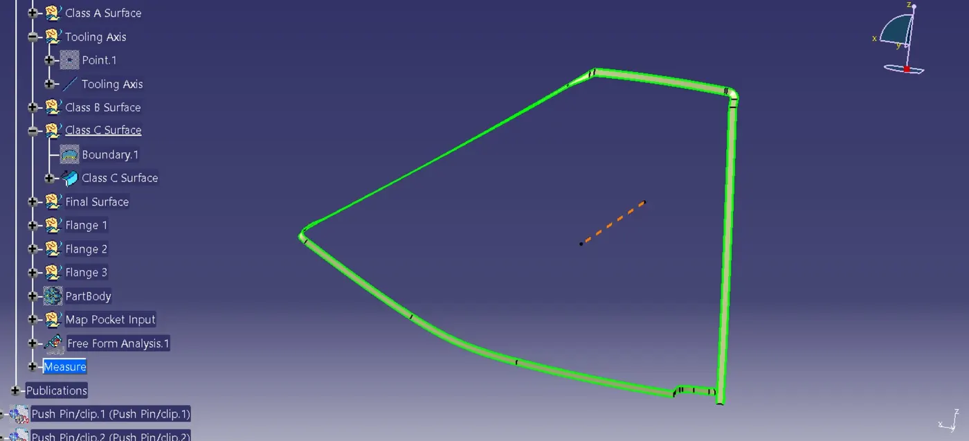
Class C Surface is the joining surface between Class A Surface and Class B Surface to obtain the solid plastic model.
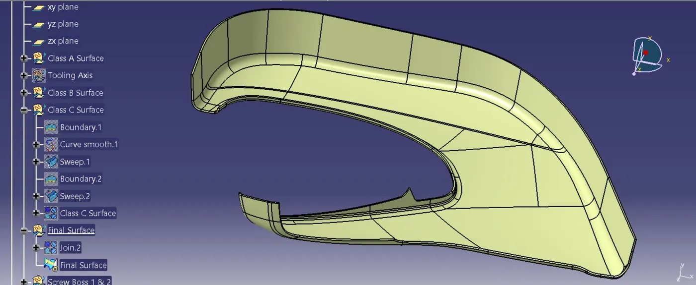
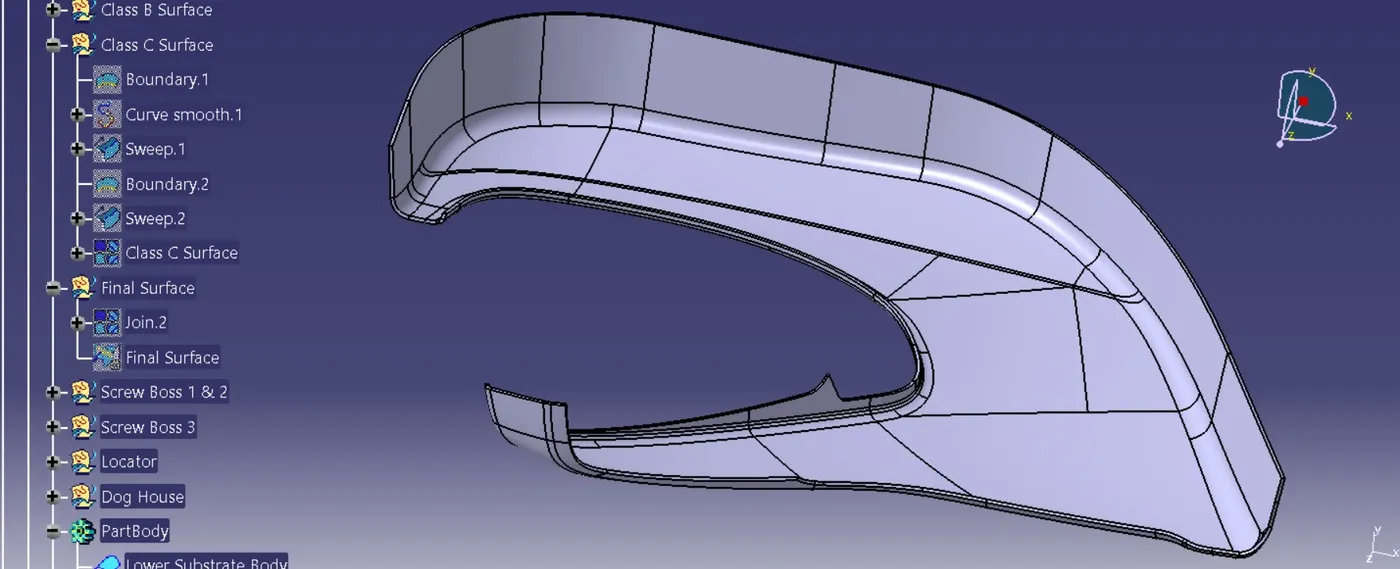
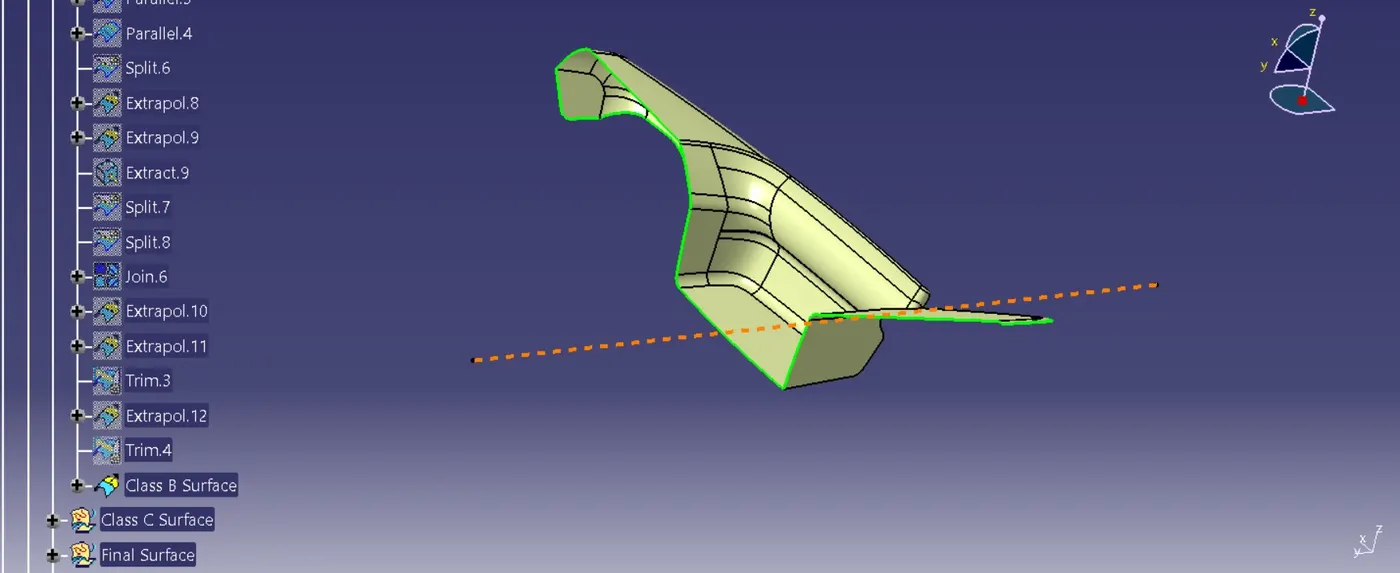
Final Surface and Part Body
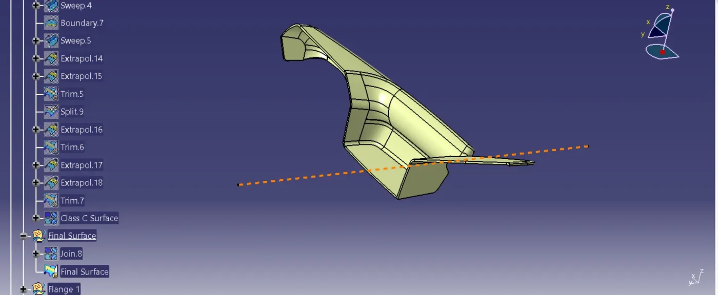
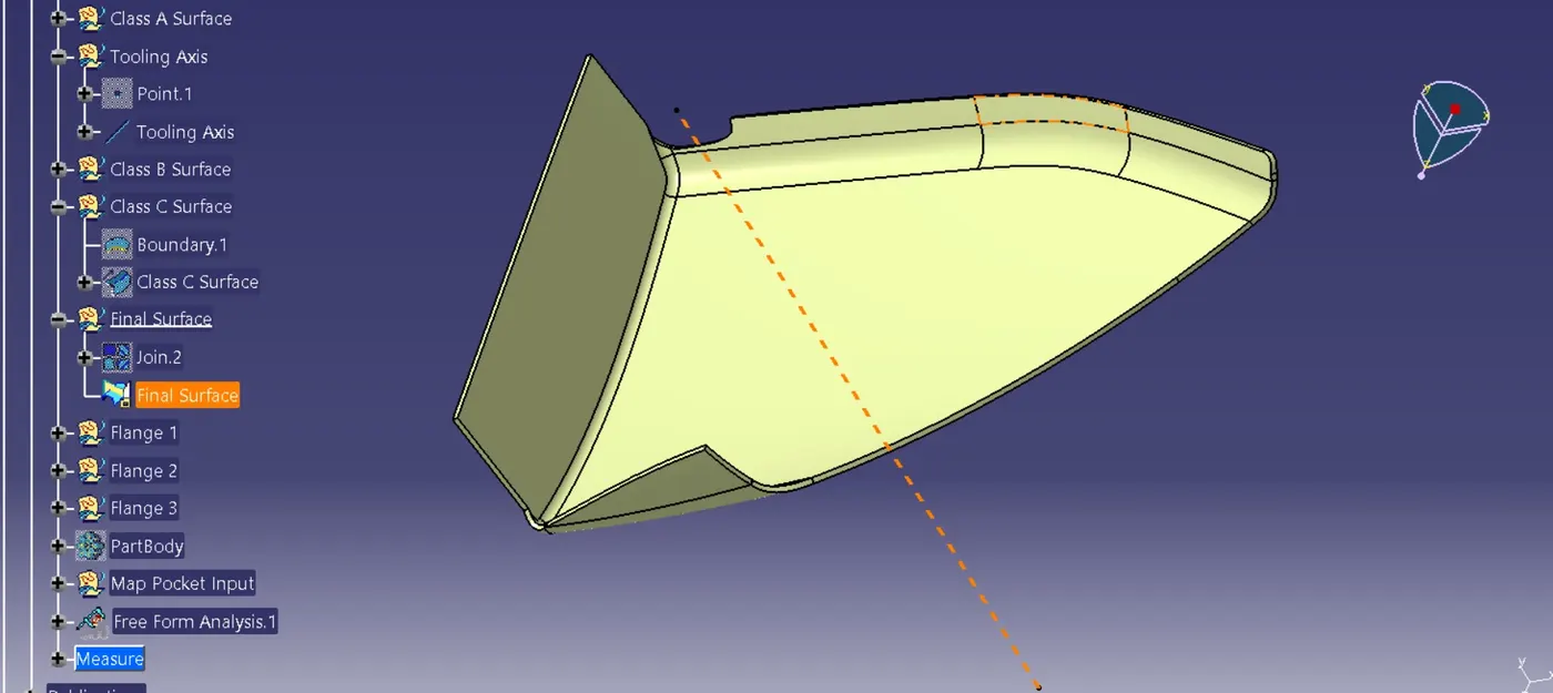
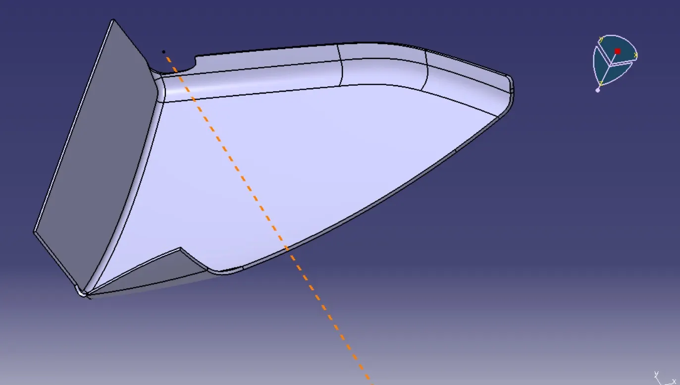
Final Surface is obtained by joining Class A Surface and Class C Surface, then using Trim command with joined surface and Class B Surface to obtain the closed surface model.
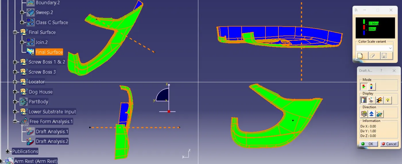
Draft Analysis
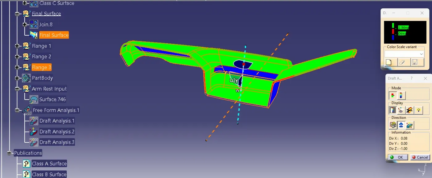
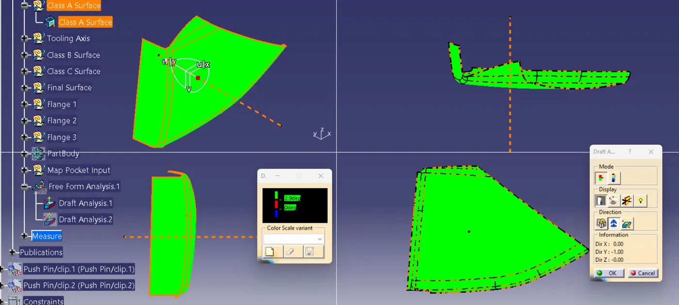
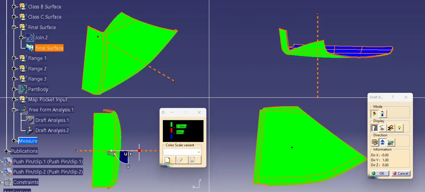
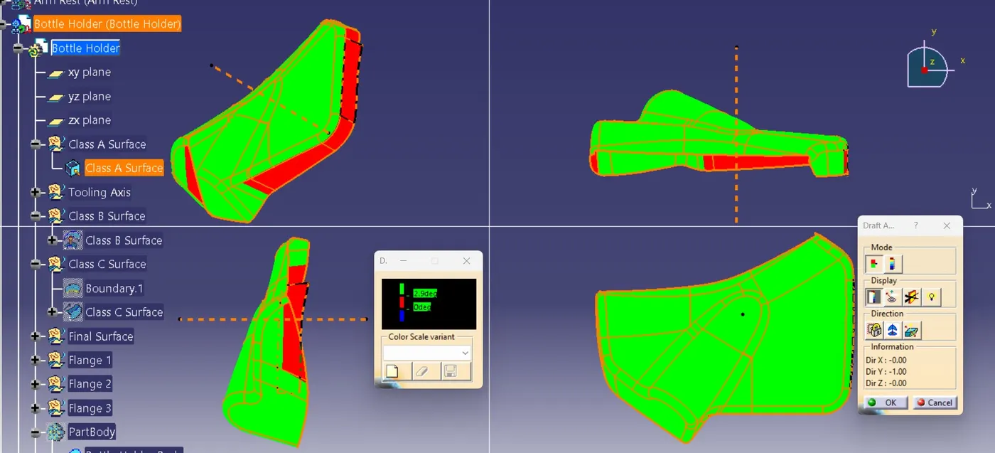
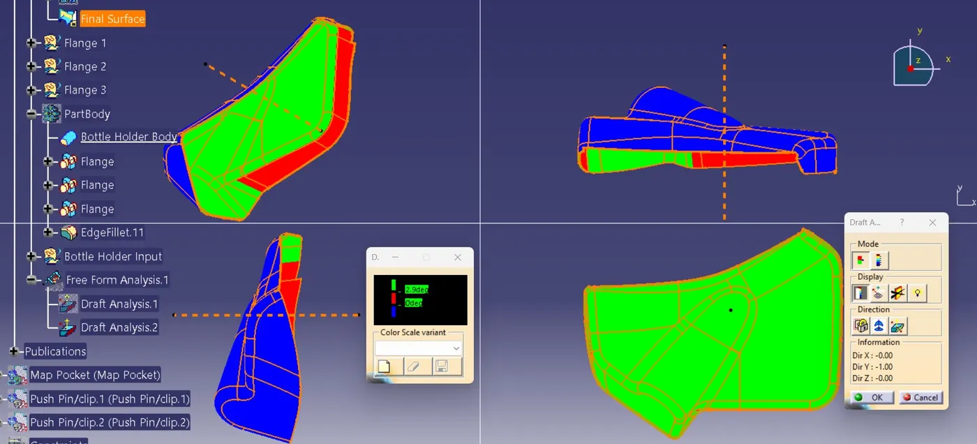
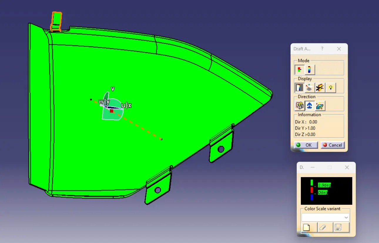
Choosing the Class A surface perform Feature Draft Analysis with respect to Tooling Axis. Green color indicates the surface can be manufactured using core and cavity method. Given draft angle of 2.9 degrees for door trim Class A Surface.
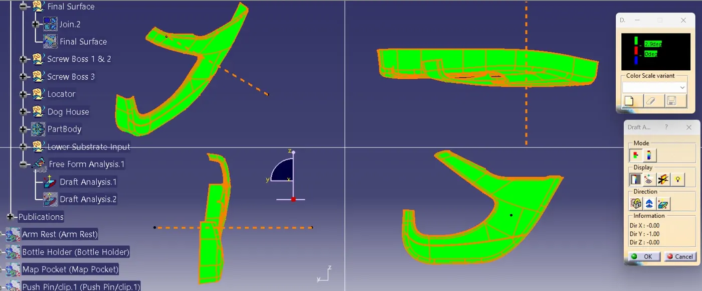
Draft analysis on final surface of lower substrate
Arm Rest
Arm rest offers comfort to the occupant while being structurally mounted to the door trim. Flanges are created for heat stakes or screw bosses to secure it to the main panel additionally reinforcement ribs are also provide for added strength.
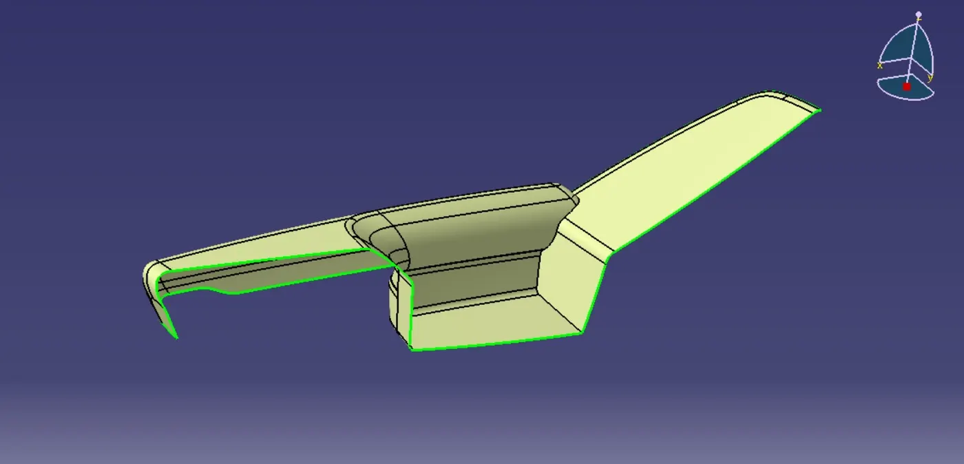
Class A Surface
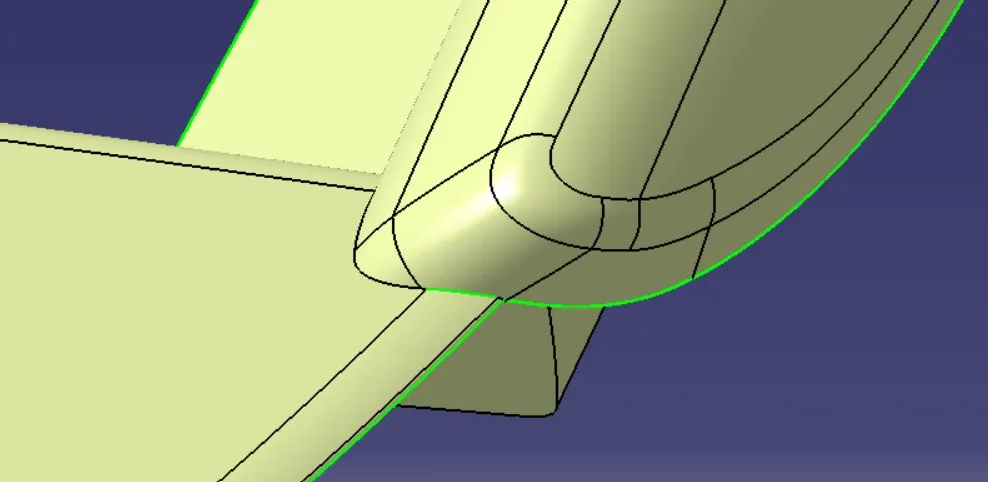
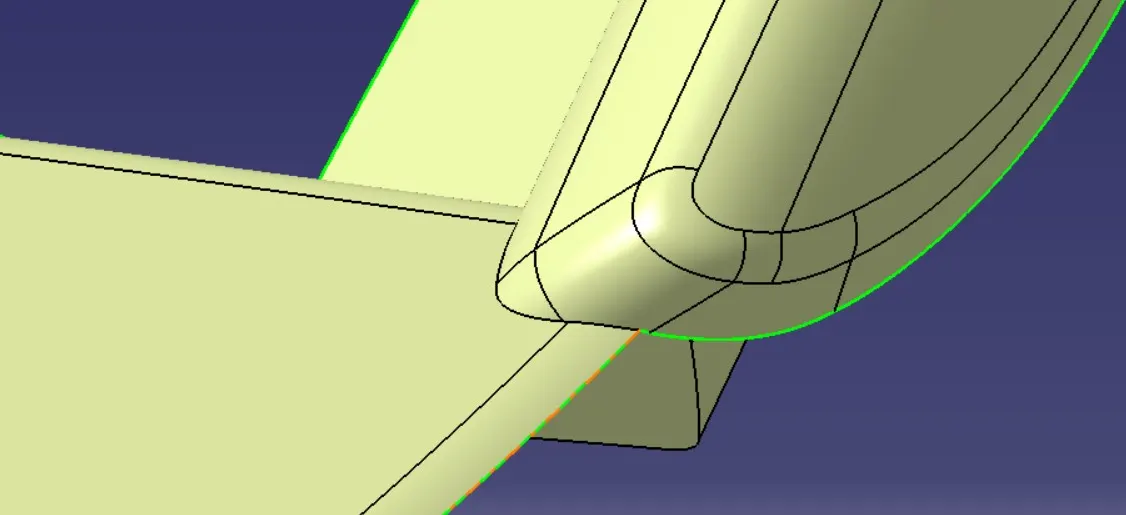
Final Class A Surface
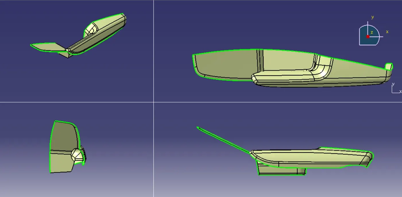
Tooling Axis
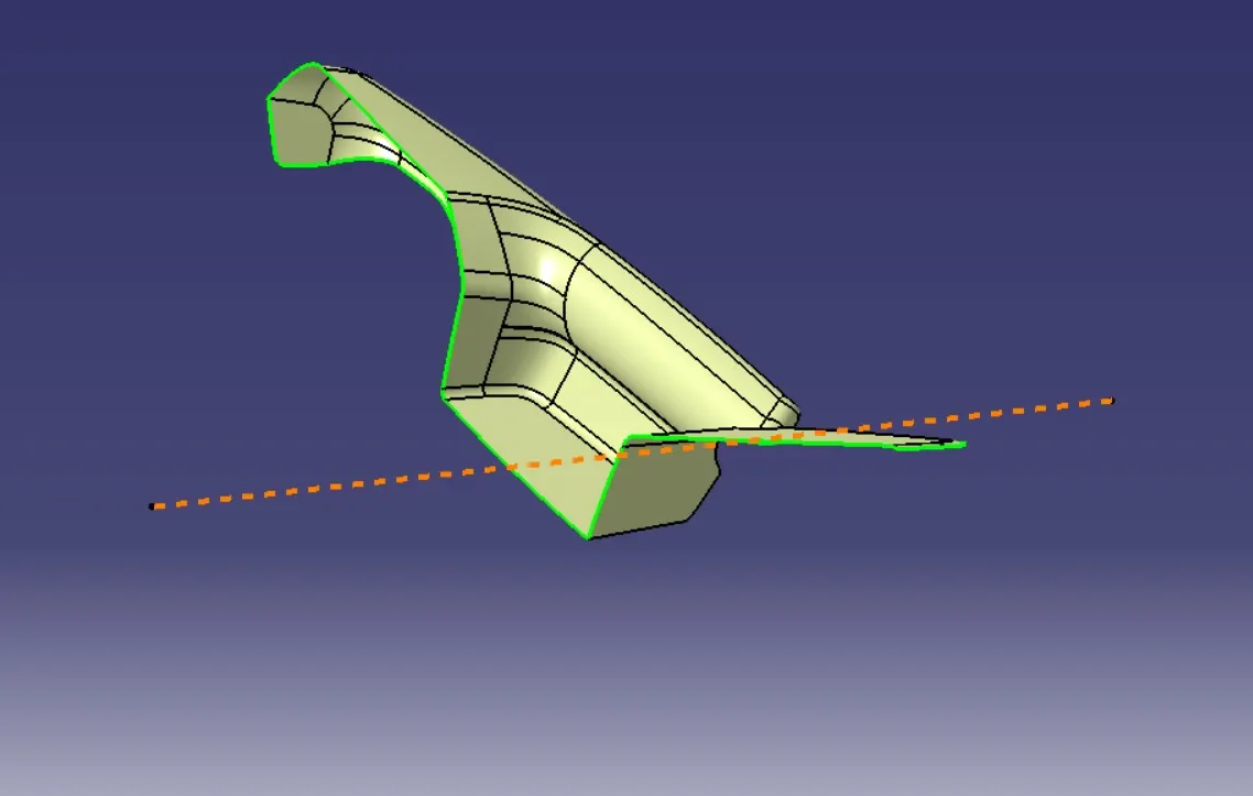
Class B Surface
Class C Surface
Final Surface and Part Body
Draft Analysis
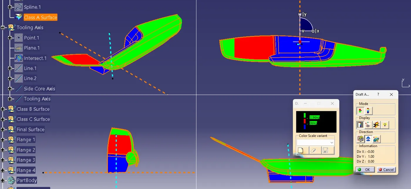
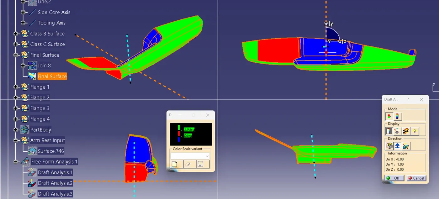
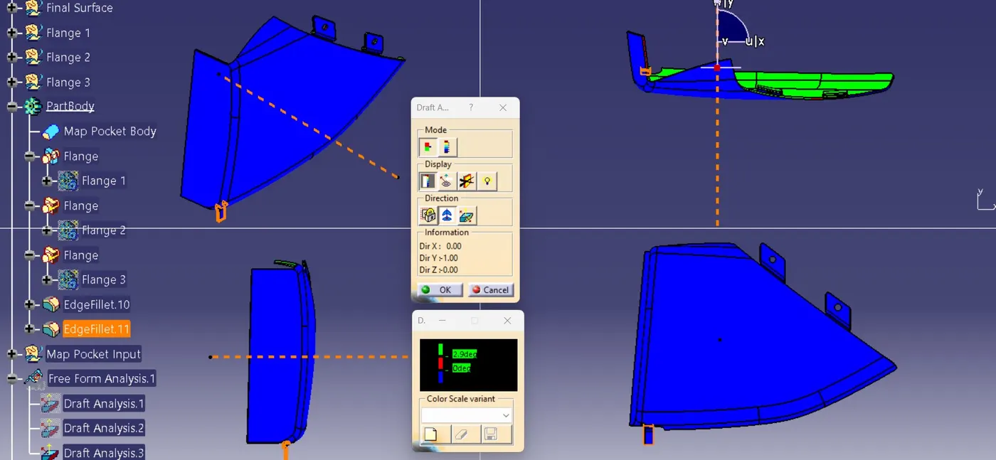
Since most part are not clearing draft analysis, side core axis is created for manufacturing feasibility.
Draft analysis on final surface of arm rest:
Map Pocket
Map pocket provides storage space for small items. Flanges are created on B surface for mounting and assembly to other part of door trim.
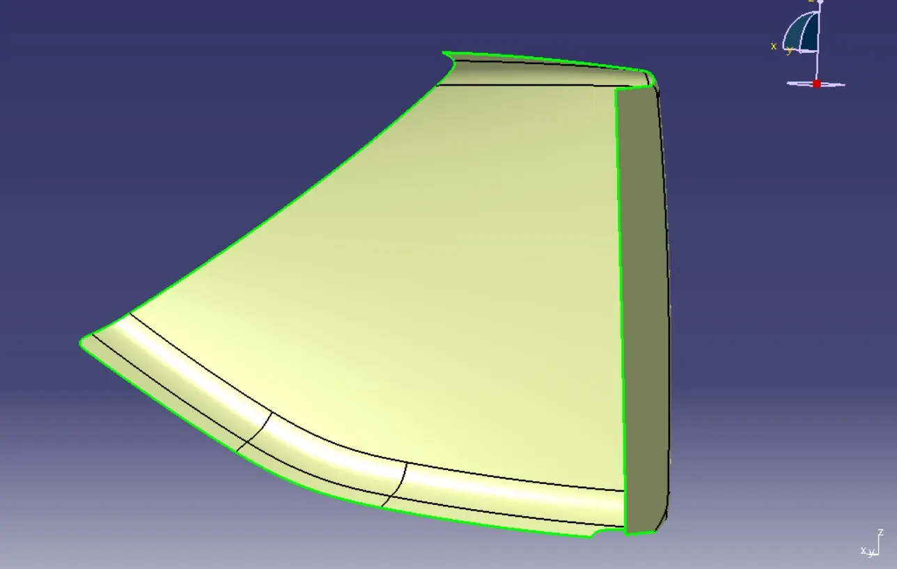
Class A Surface
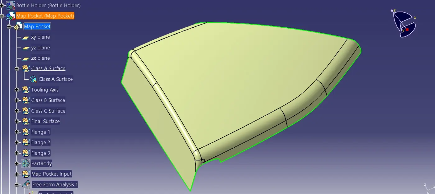
Tooling Axis
Class B Surface
Class C Surface
Final Surface and Part Body
Draft Analysis
Bottle Holder
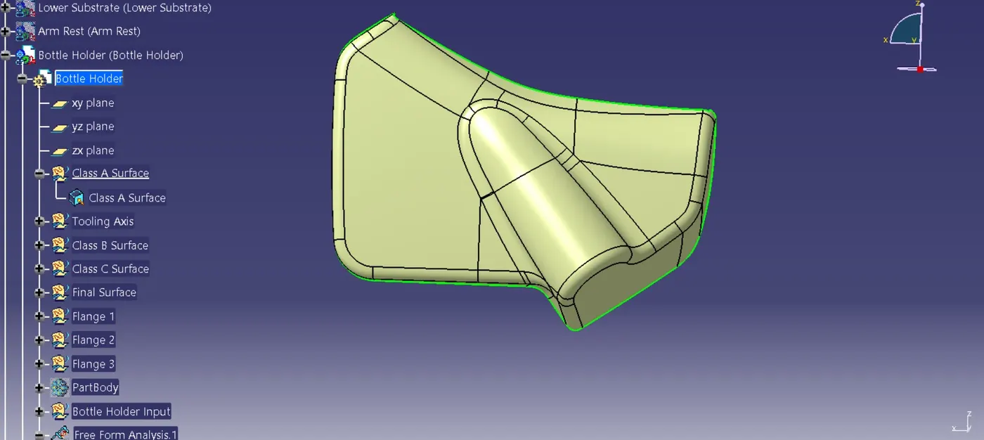
Bottle holder securely holds bottles or cups in door panel.
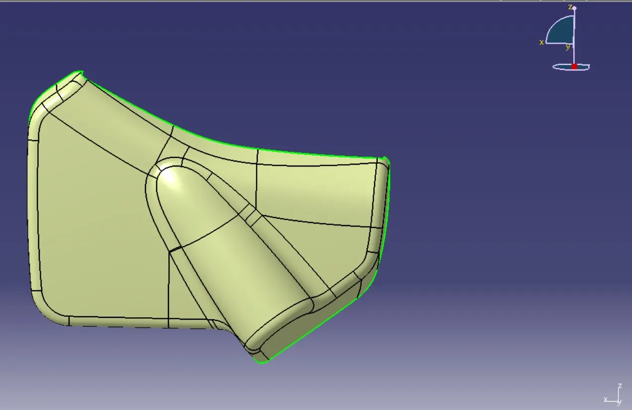
Class A Surface
Tooling Axis
Class B Surface
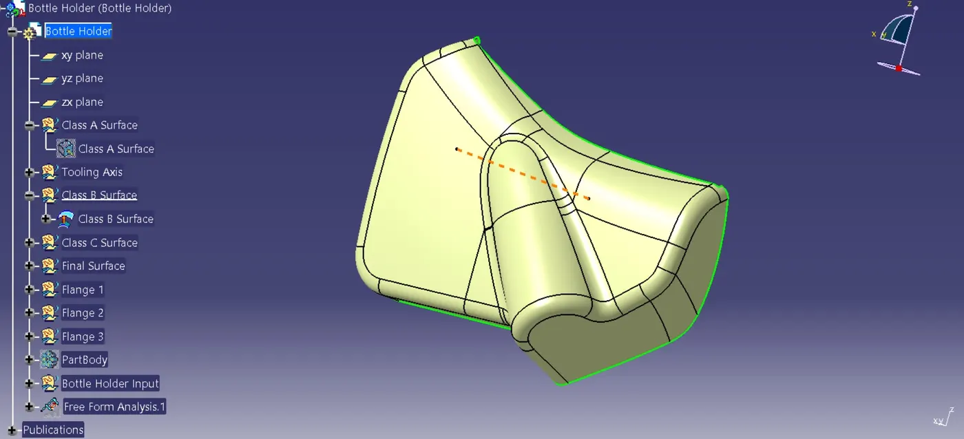
Class C Surface
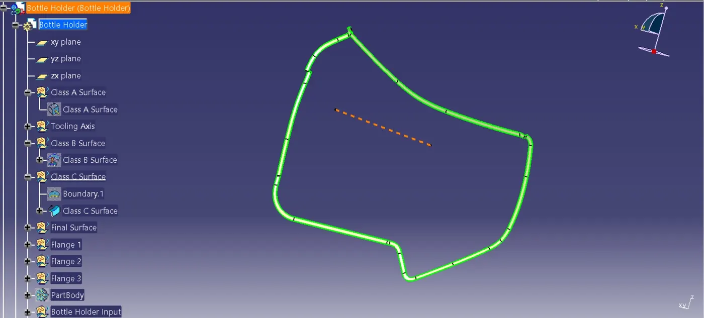
Final Surface and Part Body
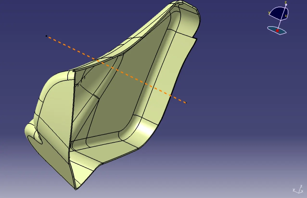
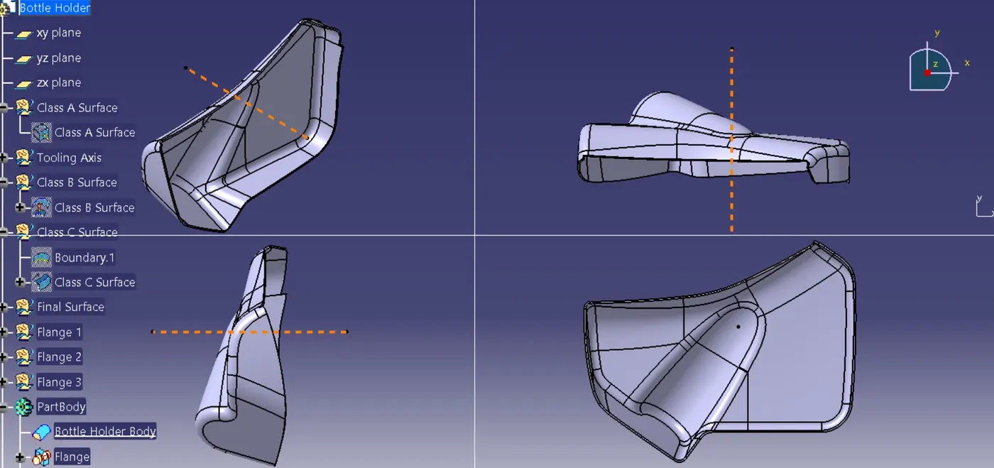
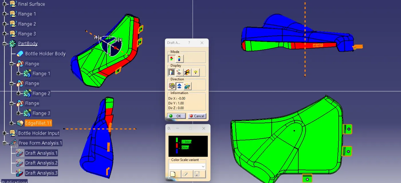
Draft Analysis
B Side Features:
Flanges
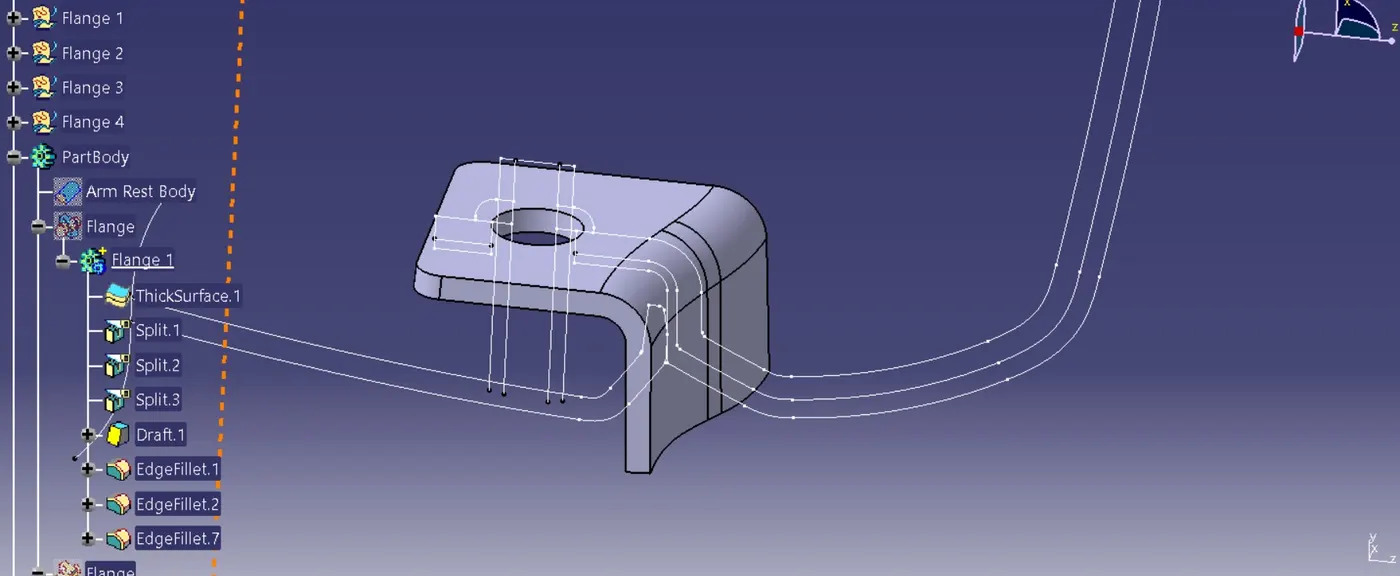
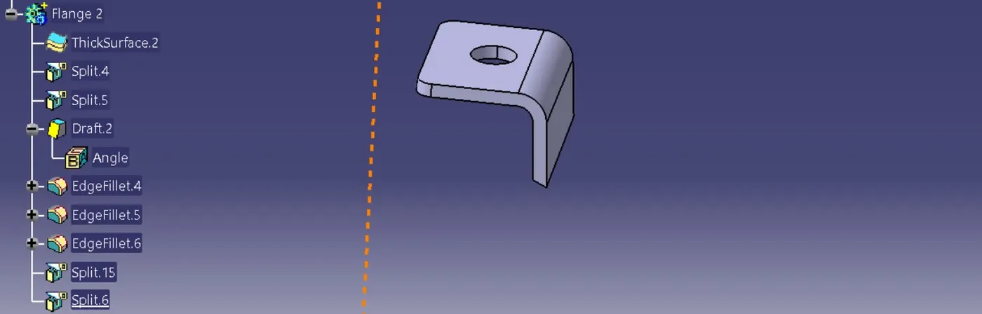
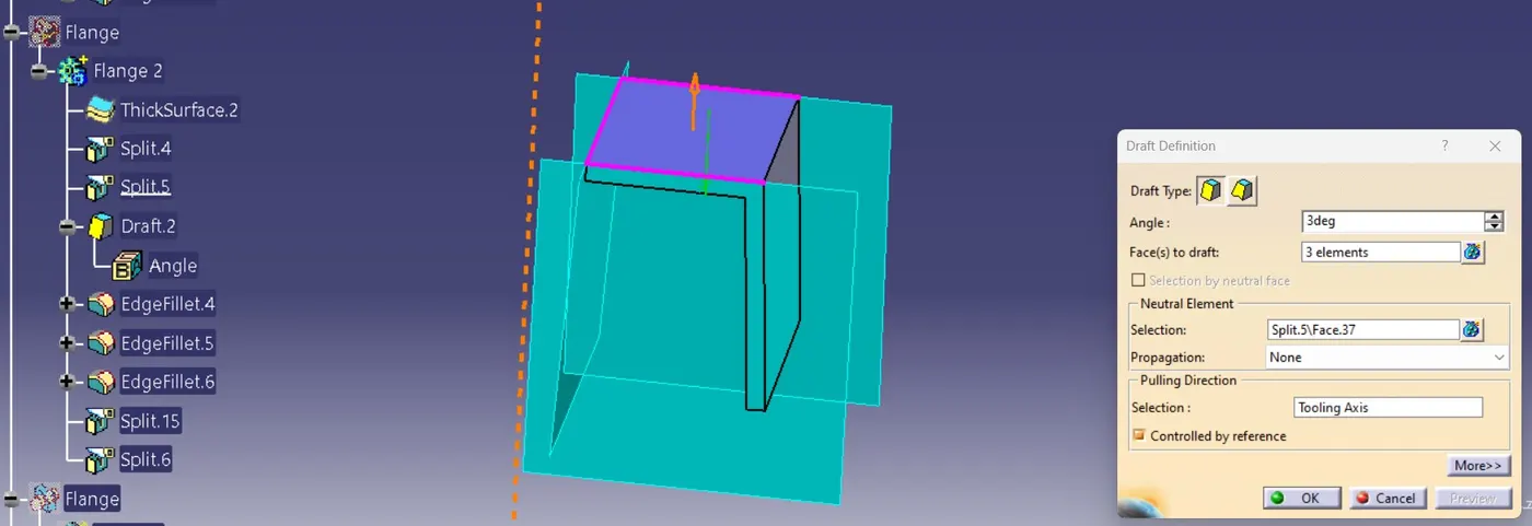
A flange is a flat or curved edge on a component that is commonly used for attachment, strengthening, or sealing. Flanges are an important B side component of vehicle door trim panels because they enable functionality and manufacturability while maintaining the design lightweight and cost-effective. Flanges are also incorporated near weak points, such as near thin walls or corners, to prevent stress concentration and enhance durability. They are generally created using Class C Surface and Class B Surface as reference. Here for door trim panel, with reference to master section provided and class B & C Surfaces, the flanges are created. Proper draft and fillets are given to avoid sharp corners.
Flange created using master section as reference:
Flange created meeting design and manufacturing criteria, also provided proper draft and fillets at sharp corners to each flanges:
Heat Stake
Here for door trim panel heat stakes are used to secure components such as the armrest, map pocket and bottle holder to the lower substrate.
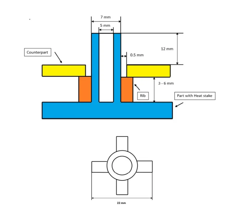
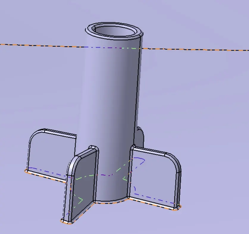
Referring to master section heat stakes are created on appropriate points on lower substrate and also design criteria for heat stake include:
- Length of the Rib - 22 mm
- Height of the Ribs - 3 mm to 6 mm
- Inner Diameter of Heat Stake - 5 mm
- Outer Diameter of Heat Stake - 7 mm
- Minimum clearance between heat stake and counterpart - 0.5 mm
- Minimum fillet of Heat Stakes - 0.25 mm
- Minimum Draft Angle of Heat Stakes - 0.5 degrees
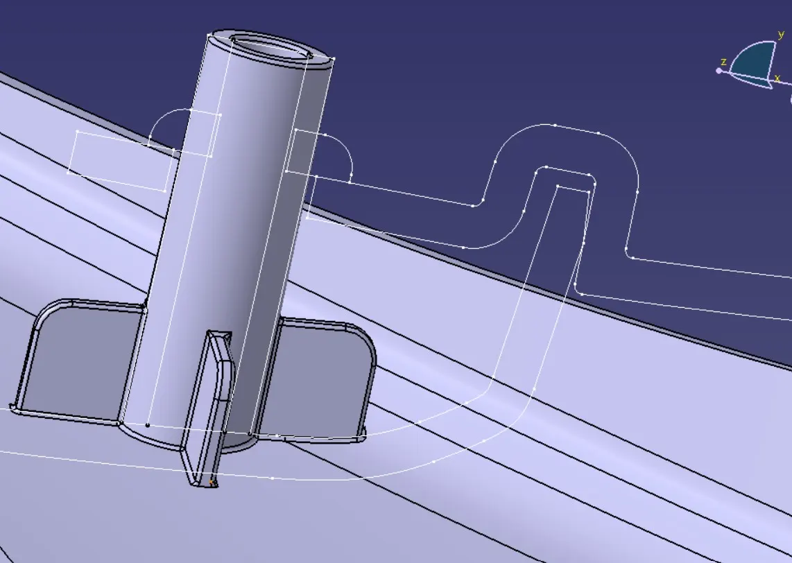
Screw boss created using master section:
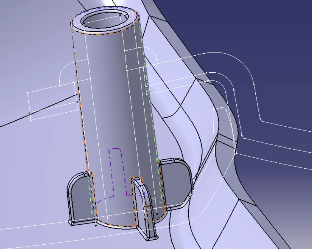
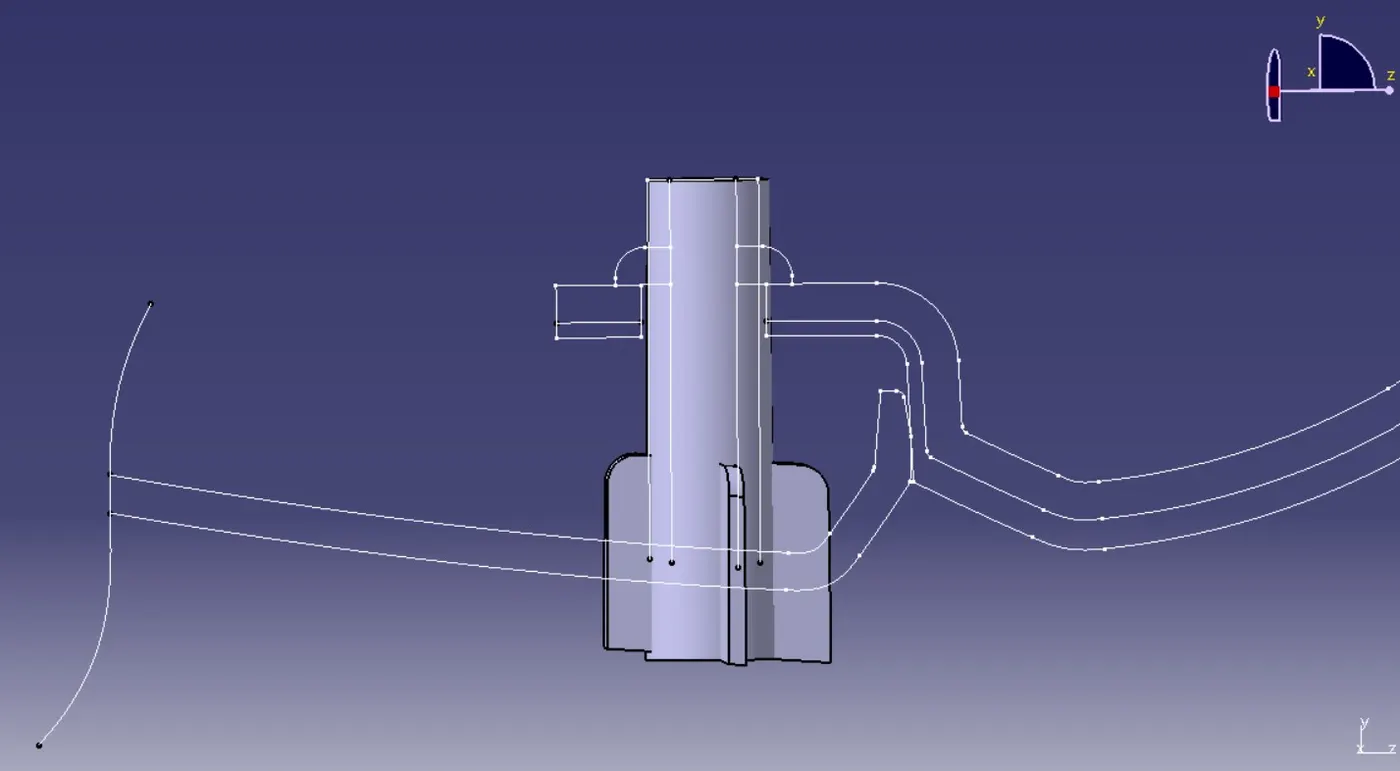
Screw boss created meeting design criteria:
Locators
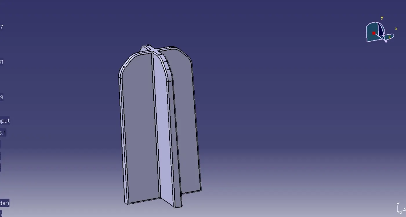
The main purpose of locators are to ensure precise alignment between the components in door trim and also with door panel. Locators are provided to control the degrees of motion of the component or fix its motion. There are two types of locators, 2-way and 4-way locator. 2-way locator restricts the motion along 1 axis i.e., 2 degrees of freedom. The 4-way pin restricts 4 degrees of freedom along the 2 axis.
Design criteria for locator:
- Height of the locators should be 1 mm (or) 2 mm greater than the heat stakes
- Thickness, fillet and draft angle are of same as rib design rules.
- Ideal Chamfer value - 3 mm x 45 degrees
- Ideal length of the locators - 15 mm
Here in this Door Trim, two 4 way locators are provided in lower substrate to control and fix the component.
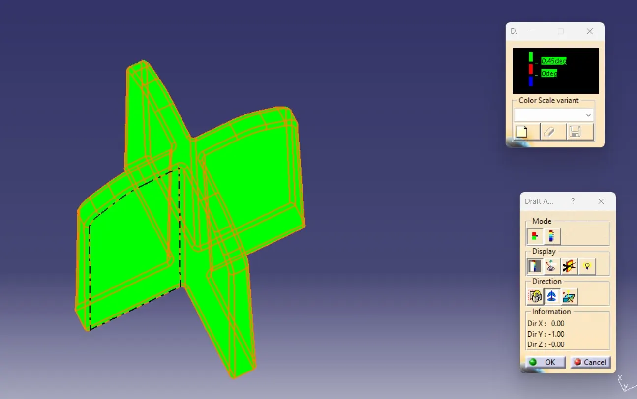
Draft analysis of locator:
Dog House
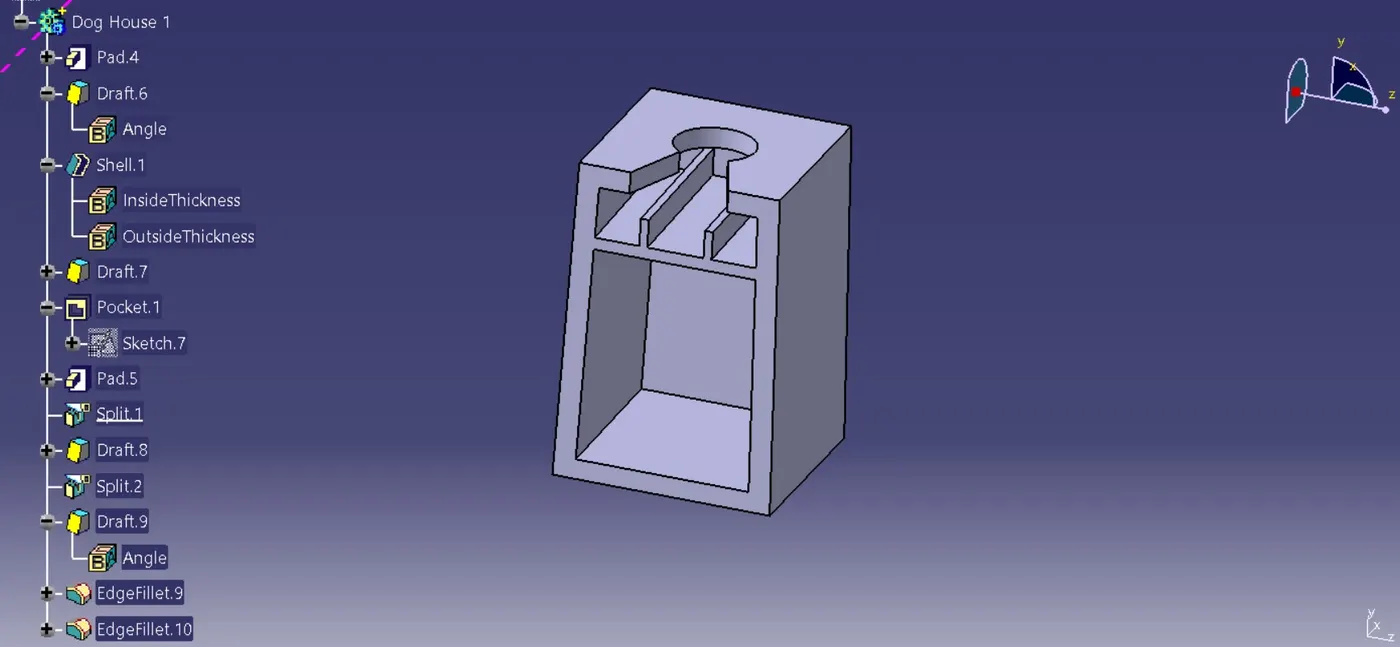
Dog houses are created to prevent sink mark on the Class A surface that could be result from screw bosses installation, and additionally solving length challenges for screw bosses installation of which needs to be joined to other components.
Design criteria followed to create dog house:
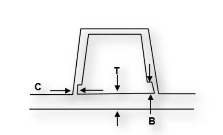
- C thickness should be 40% of the main wall thickness of T
- The minimum width of the dog house is 12 mm.
- The height of B should be 3-6 mm
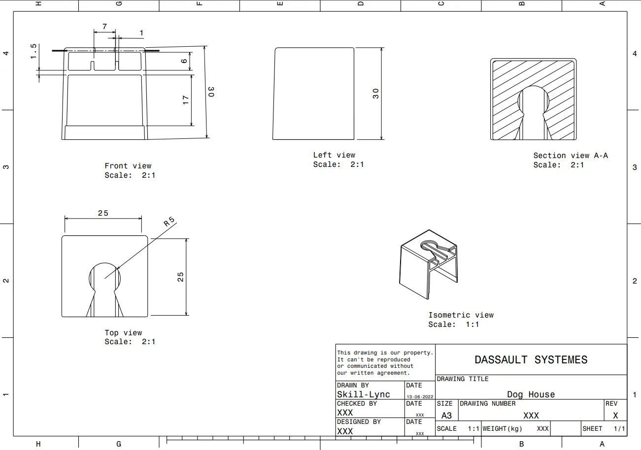
Steps involved to create dog house:
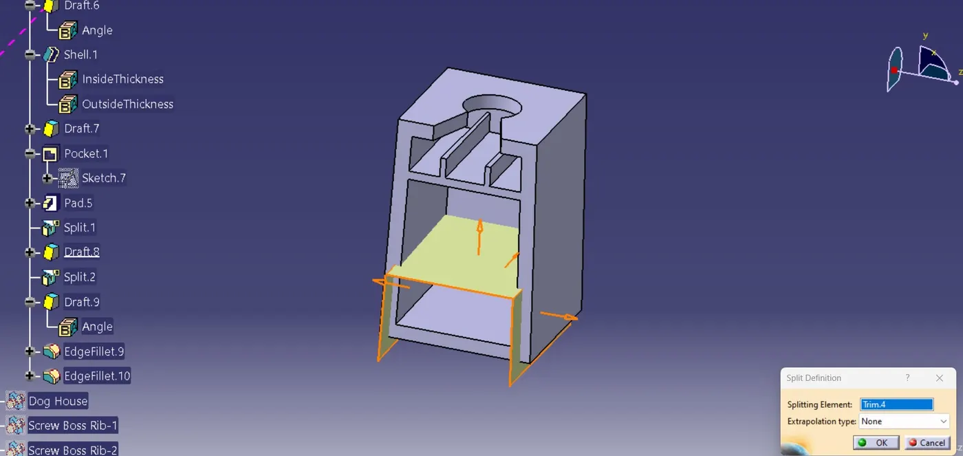
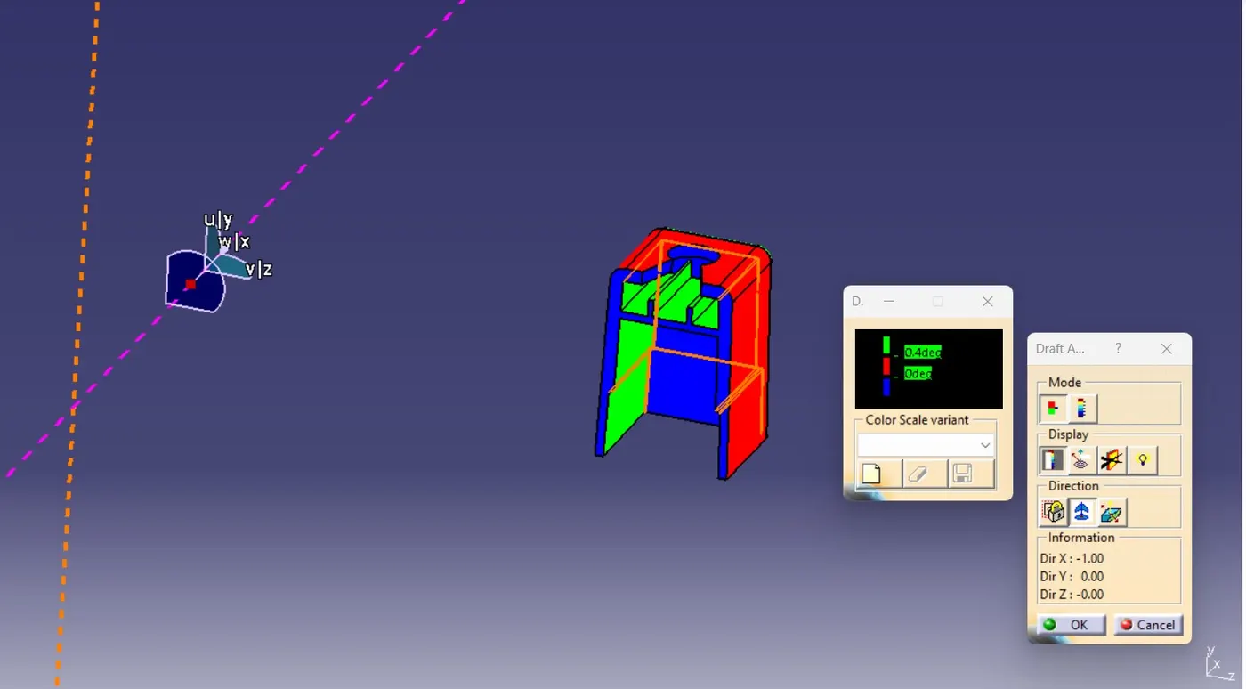
- Create a Side Core Axis by using the point created of Tooling axis along with X component.
- Create sketch for dog house by creating a positioned sketch command. Use Pad command on sketch, then by using Shell command with dog house thickness to obtain the outer wall of dog house.
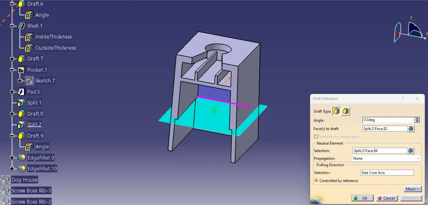
- Provide draft angle of 1.5 degrees to the outer wall of dog house with respect to tooling axis.
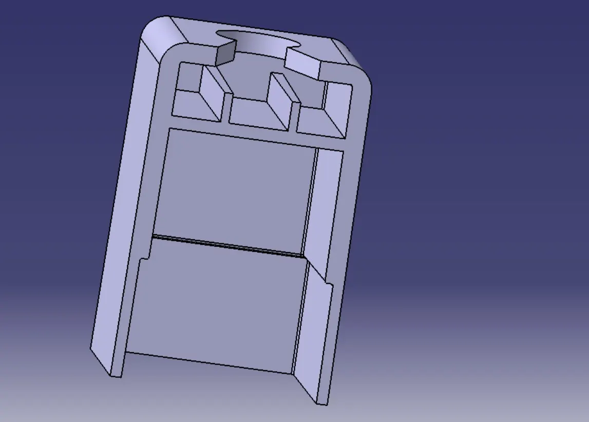
- Create ribs inside the dog house with reference to dog house design criteria as shown in image above using Sketch and Pad command.
- The inner walls are properly drafted by giving draft angles of 0.5degrees along with side core axis and fillets are also provided by considering the design rules.
- Provide proper slot using Sketch and Pocket command meeting dimensions with reference to design criteria for assembly of Pushpin clip.
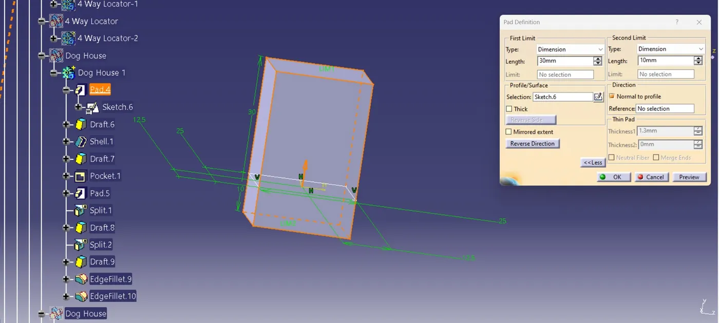
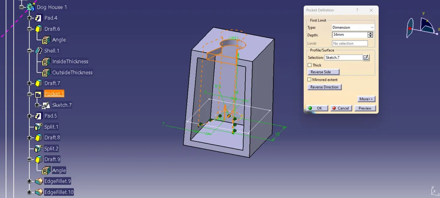
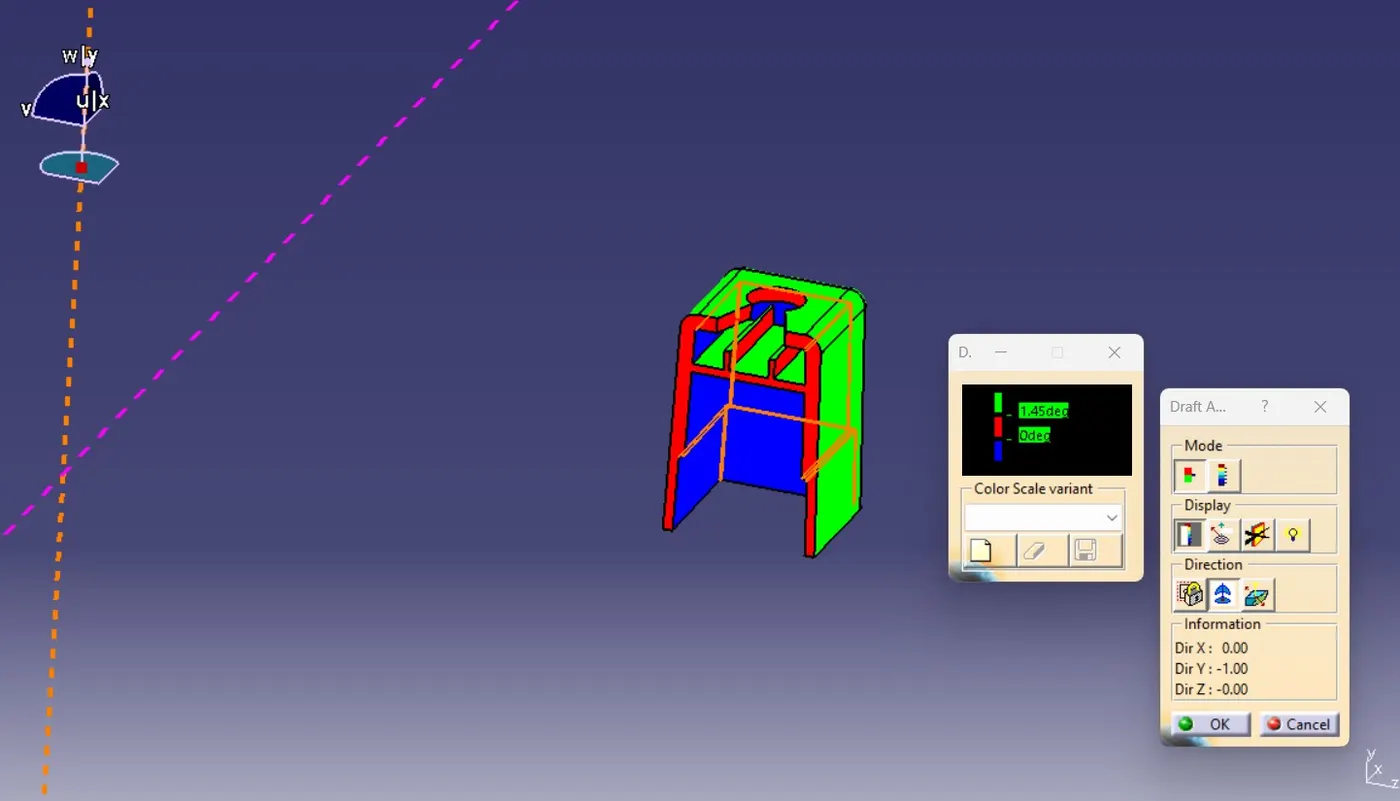
Draft analysis of dog house with respect to Tooling Axis:
Draft analysis of dog house with respect to Side Core Axis:
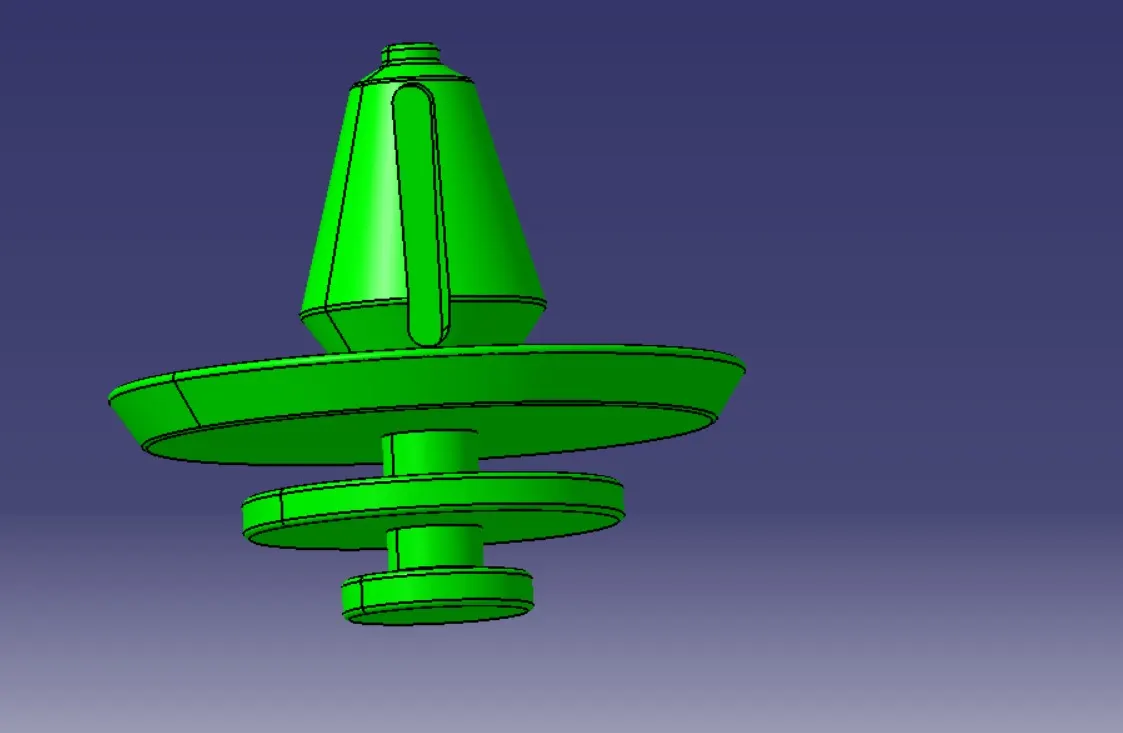
Pushpin Clip
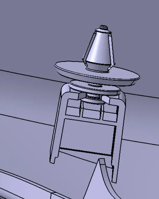
Assembly of Pushpin Clip to Dog House
Assembly constraints Fix and Coincidence are provided for proper assembly of pushpin clip to dog house.
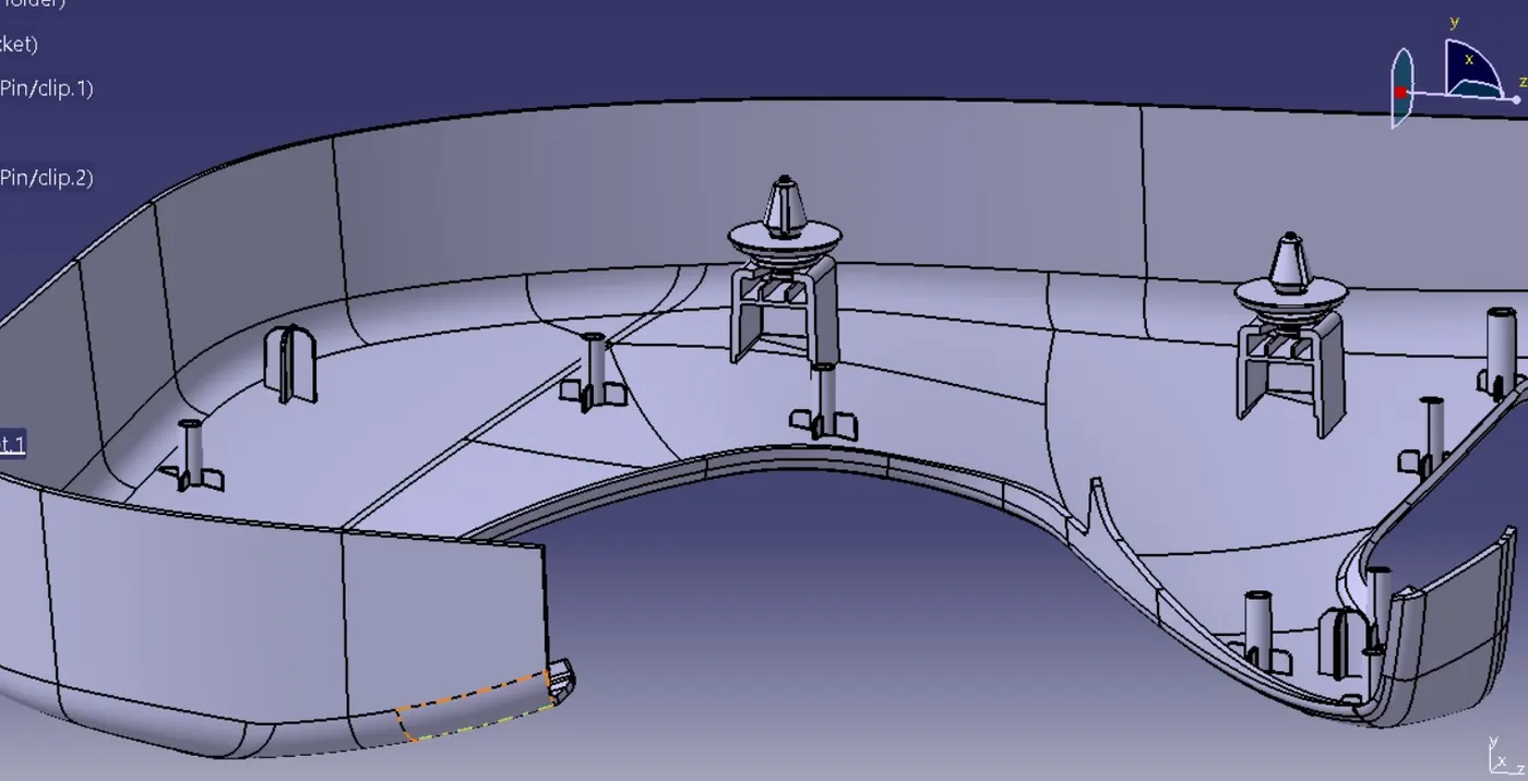
Door Trim Components With B Side Features
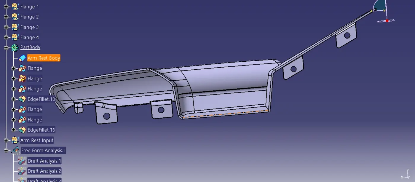
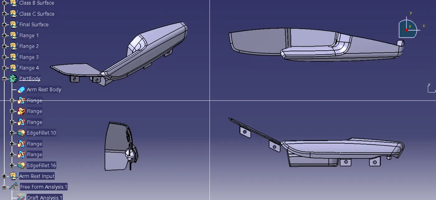
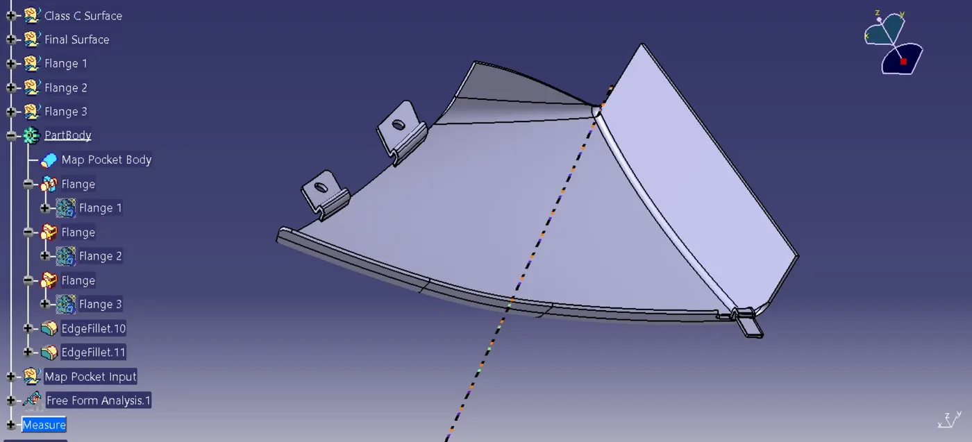
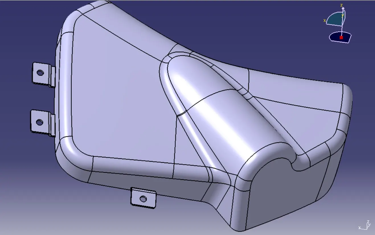
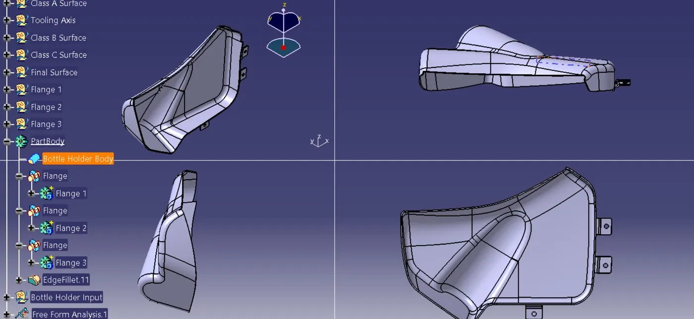
Draft Analysis of Each Component With B Side Features
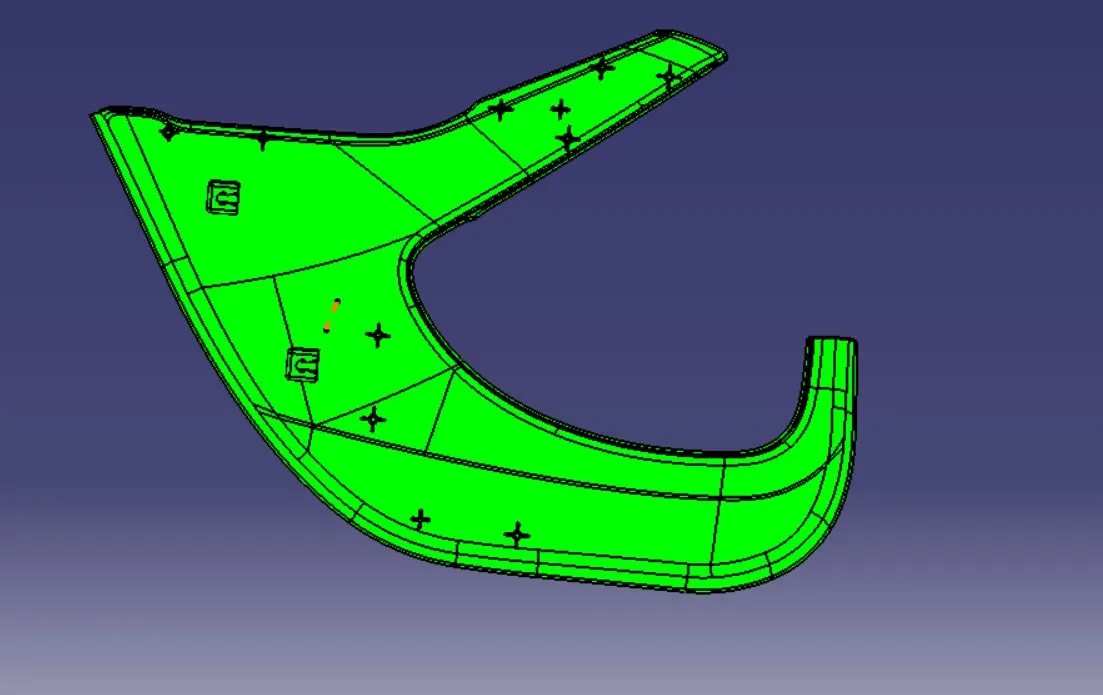
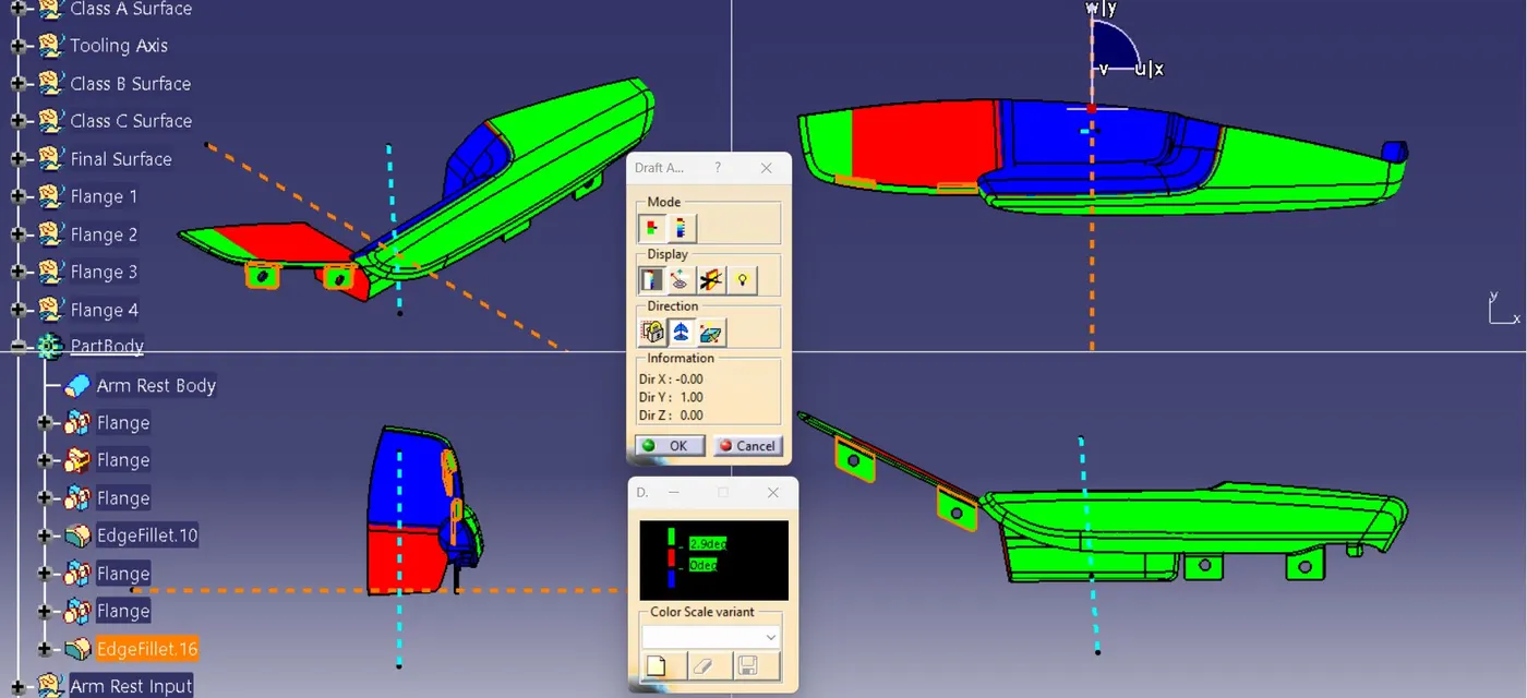
Assembly of Door Trim Panel
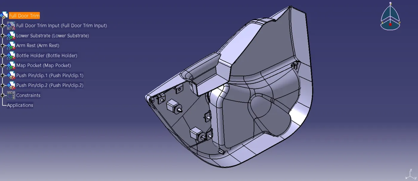
Door Trim with B Side Features
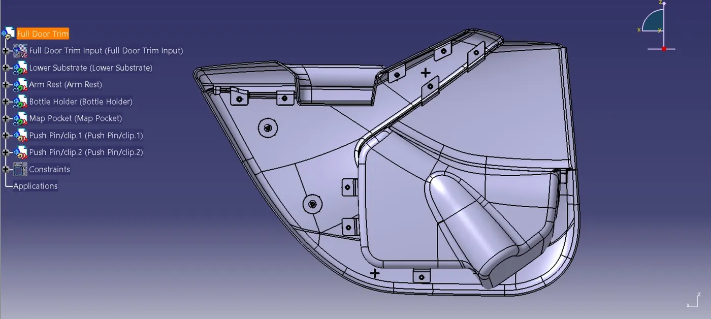
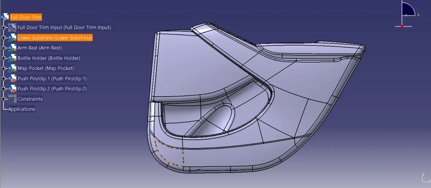
Door Trim Class A Surface
CONCLUSION
The design of the full door trim and its attachment features on the B-side ensures functional efficiency, manufacturability, and compliance with automotive standards. Thus the CAD model for door trim panel has been created considering following inputs as like in OEM and tier1 companies. End draft analysis of each components were performed to check manufacturability.