Week 12- Final project
DEVELOPMENT OF A DOOR TRIM PANEL
OBJECTIVE:
To design and development of a Door Trim Panel by using CATIA V5 by following the design considerations in the industry from the given Class-A with the Master sections.
GIVEN:
Thus the following as the Input of this Plastic components Class-A Surface with the Master sections.
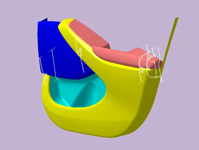
From the given Class-A surfaces and the ref Master sections thus the Nominal thickness of following Plastic components are 2.5 mm. And also ensured that all the Class-A surface quality.
TOOL USED: CATIA V5
DOOR TRIM PANEL
The door trims are the interior parts that contain various components such as the Arm rest, Lower Substrate, Map pocket, Bottle Holder, Switch bezel, Speaker and other features also. And aesthetic trims designed in a way to enhance the user experience of the driver and the passenger. In this given Door Trim which contains as followings are,
1. Arm Rest
2. Lower Substrate
3. Map Pocket and
4. Bottle Holder.
From the given Class A Surfaces are checked by using Boundary with the Continuty(Tangent-G2 or Curvature G3 continuty) of the given surface.
DOOR TRIM_PART CREATION:
1. ARM REST
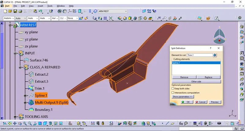
From the Given Class-A surface we found the some of the quality issues over there like complex regions are in the Arm Rest Class-A surface and here thus the surface gets repaired for the further proceeding to convert into final plastic component. And the following as repaired Class-A of Arm Rest,
STAGE_1: TOOLING AXIS CREATION
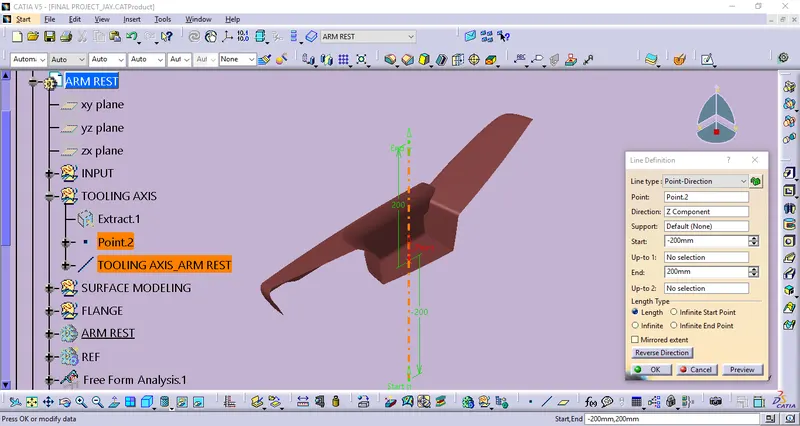
The Tooling Direction which one is the direction that the mold pulls apart. The mold is built in two separate halfes of like Cavity side and the Core side. The Core pulls out from the Cavity along with the certain direction which is called as Tooling direction or Tooling Axis.
STAGE_2: DRAFT ANALYSIS FOR CLASS-A
By using of Feature Draft Analysis with the Minimum draft angle of 3 deg along with the above Main tooling axis. Thus the results shown here as following as,
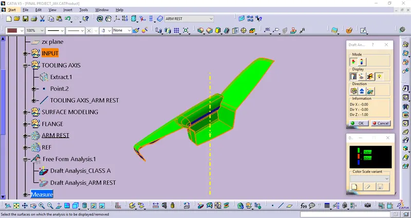
Noted: From the Draft Analysis results may use add on another tooling like side cores which will clear the draft analysis.
STAGE_3: SURFACE MODELING
STEP_1: CLASS-B SURFACE CREATION
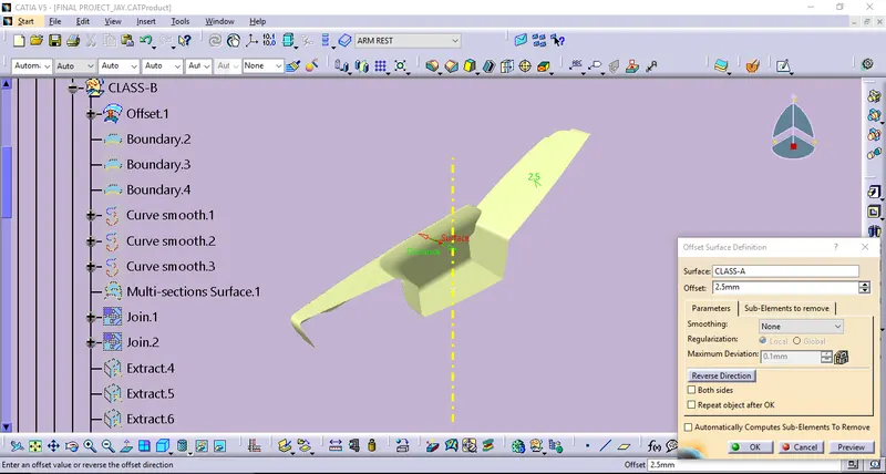
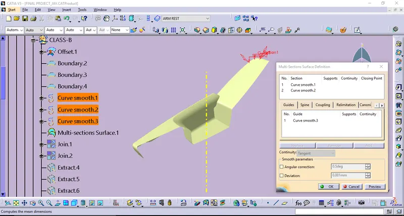
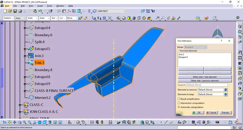
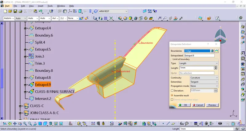
Class-B surface, In which can be easily defined as the thickness of the part and it is not visible which is inside surface of the Class-A. For the following plastic component thickness as 2.5 mm from the Input data. While offseting Class -A for 2.5 mm of thickness directly by applying Offset surface definition And then we B-side of the following one which have some of its patch holes/no surfaces obtained over there. Then the patchs will be created into simplified surfaces to be obtain the complex one which Class-B surace. And the following solvings are,
By using of Offset Surface definition.
By using of Multi-section Surface definition.
By using of Trim definition.
By using of Extrapolate definition.
STEP_2: CLASS-C SURFACE CREATION
By defining the Class-C surface with respect to the Class-A surface. From the Class -A surface edge boundaries used to performed to create the Class-C surface. And the some of its workings are,
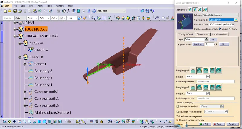
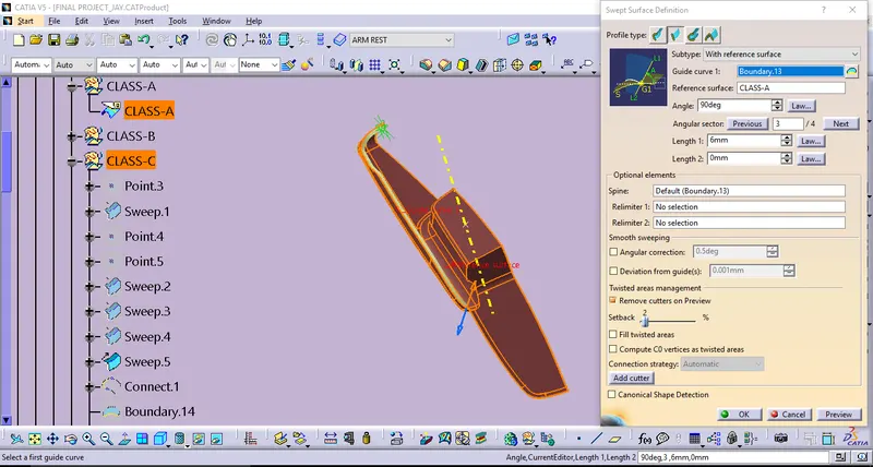
Commands used: Swept surface(type-2) with drfat direction , Swept surface(type-2) with ref surface, Swept surface(type-1) with ref surface along with the profile and guide curve, Boundary, Curve smooth, Extrapolate, & Trim.
By defining Swept Surfcae along with the guide & drfat direction.
By defining Swept surface along with the guide & reference surface.
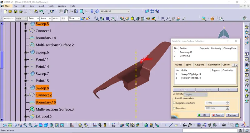
By defining Multi-Section Surface.
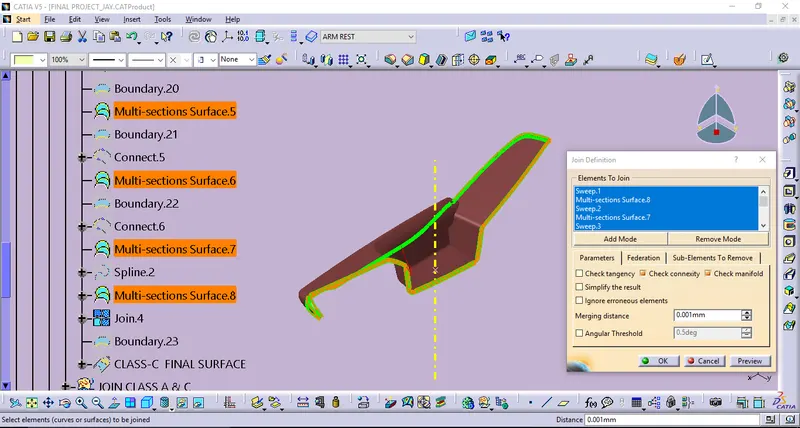
By defining Join.
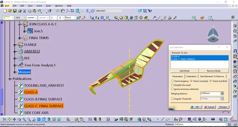
STEP_3: JOIN CLASS-A & C
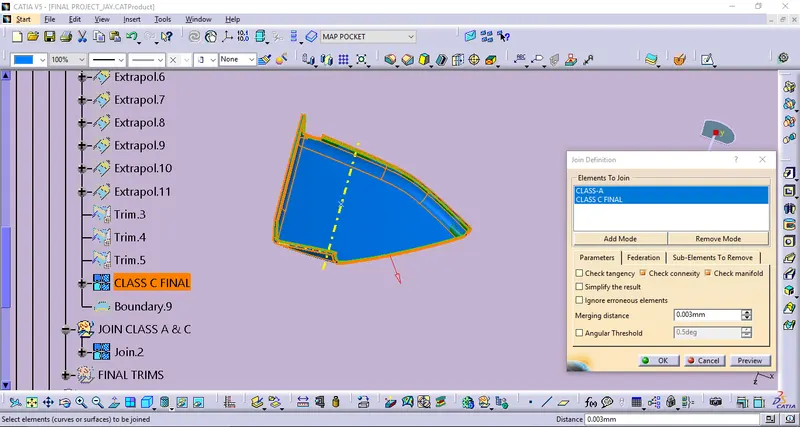
By using of Join Definition.
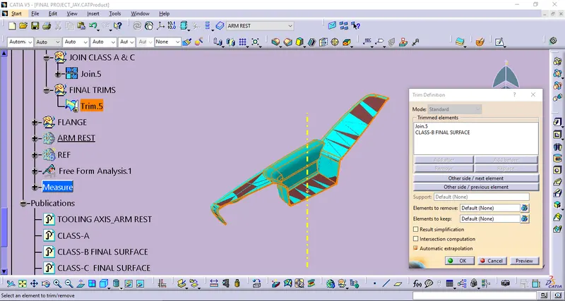
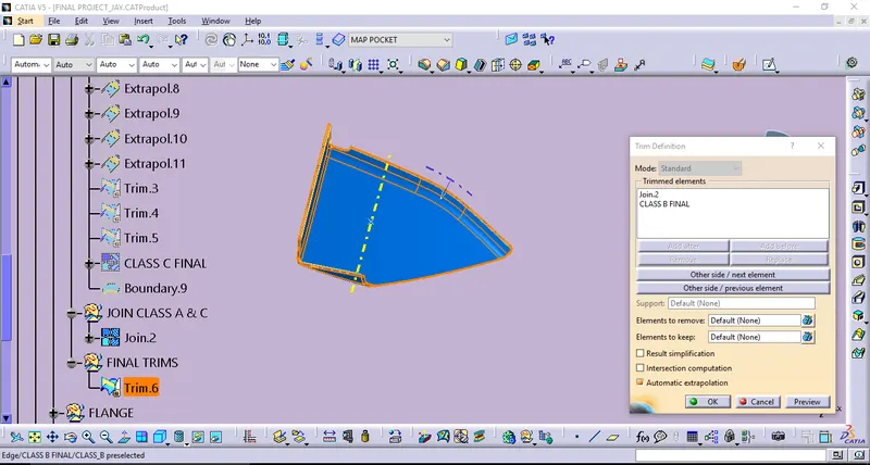
STEP_4: FINAL TRIMS
By using of Trim Definition.
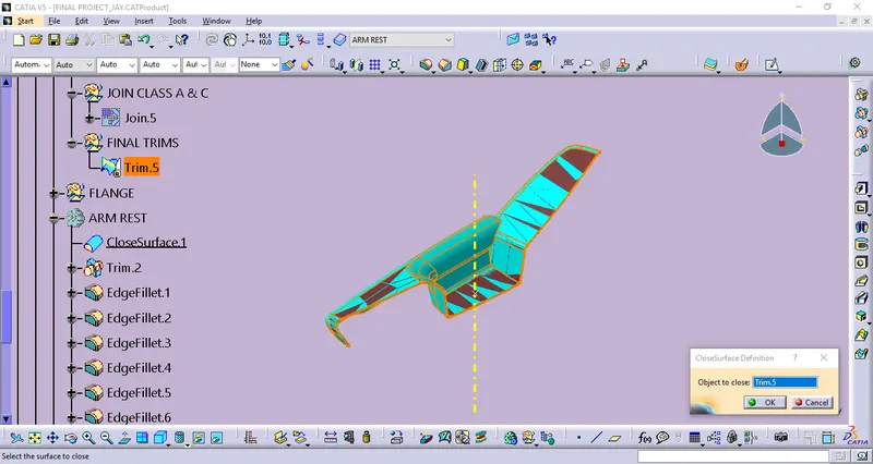
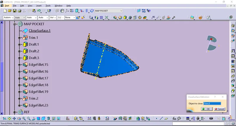
STAGE_4: SOLID PART_CLOSE SURFACE
By using of Close surface Definition.
2. LOWER SUBSTRAE:
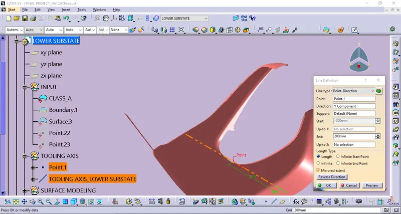
STAGE_1: TOOLING AXIS CREATION
The Tooling Direction which one is the direction that the mold pulls apart. The mold is built in two separate halfes of like Cavity side and the Core side. The Core pulls out from the Cavity along with the certain direction which is called as Tooling direction or Tooling Axis.
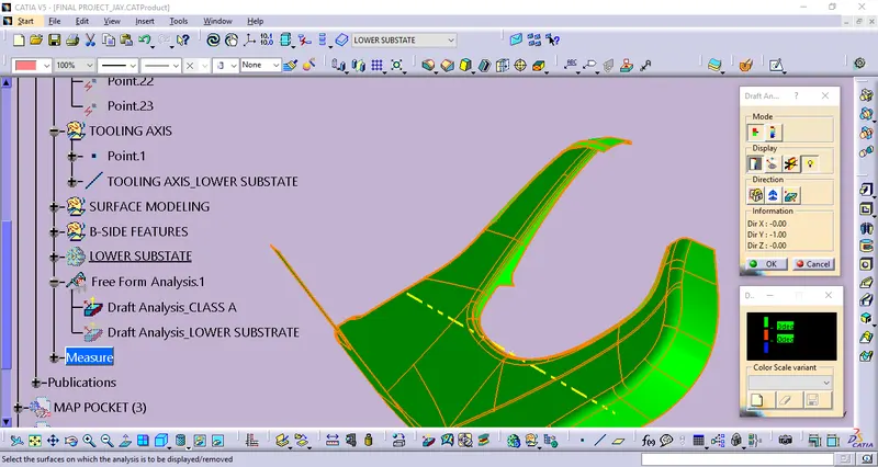
STAGE_2: DRAFT ANALYSIS FOR CLASS-A
By using of Feature Draft Analysis with the Minimum draft angle of 3 deg along with the above Main tooling axis. Thus the results shown here as following as,
STAGE_3: SURFACE MODELING
STEP_1: CLASS-B SURFACE CREATION
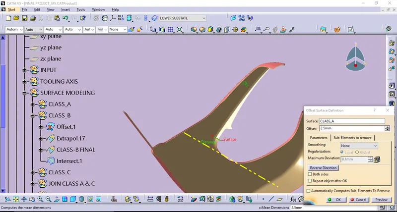
Class-B surface, In which can be easily defined as the thickness of the part and it is not visible which is inside surface of the Class-A. For the following plastic component thickness as 2.5 mm from the Input data. While offseting Class -A for 2.5 mm of thickness directly by applying Offset surface definition. And some of its solvings are,
By using of Offset surface definition.
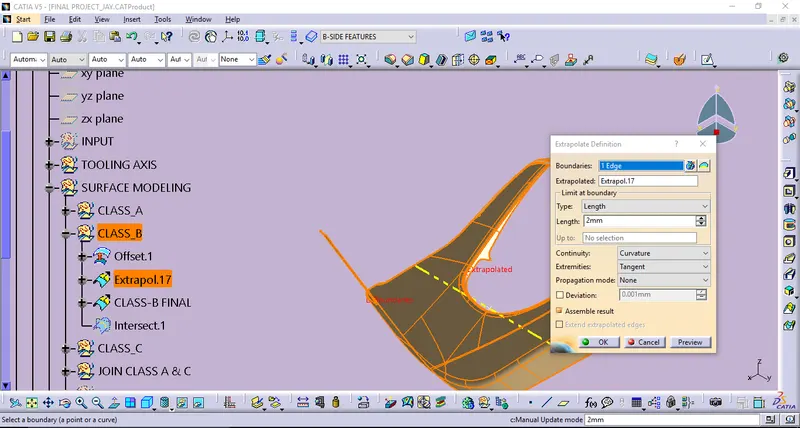
By using of Extapolate definition.
STEP_2: CLASS-C SURFACE CREATION
By defining the Class-C surface with respect to the Class-A surface. From the Class -A surface edge boundaries used to performed to create the Class-C surface. And the some of its workings are,
Commands used: Swept surface(type-2) with drfat direction , Swept surface(type-2) with ref surface, Swept surface(type-1) with ref surface along with the profile and guide curve, Boundary, Curve smooth, Extrapolate, & Trim. And some of its solvings are,
By defining Swept surface along with the guide & reference surface.
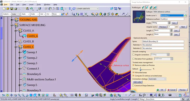
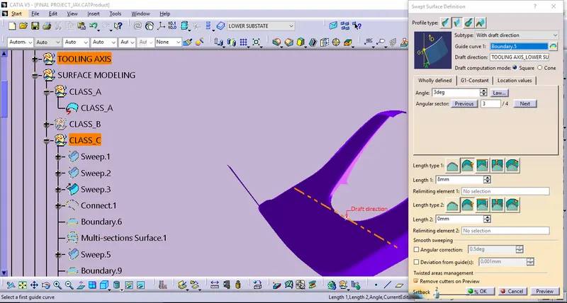
By defining Swept Surfcae along with the guide & drfat direction.
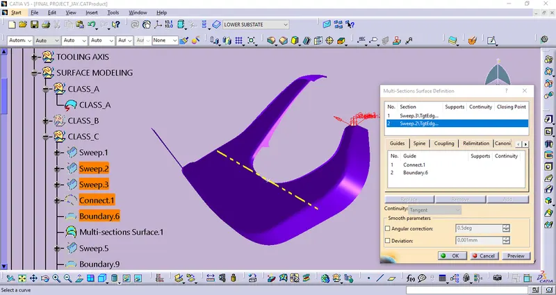
By defining Multi-Section Surface.
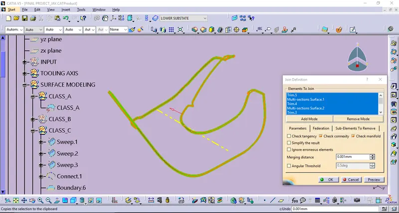
By using of Join Definition.
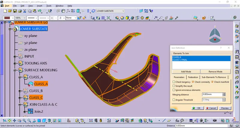
STEP_3: JOIN CLASS-A & C
By using of Join Definition.
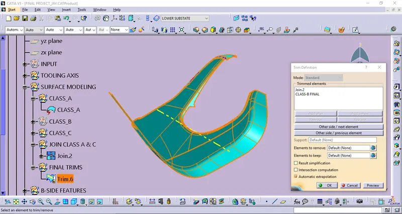
STEP_4: FINAL TRIMS
By using of Trim Definition.
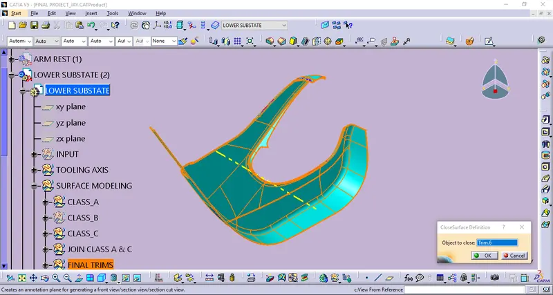
STAGE_4: SOLID PART_CLOSE SURFACE
By using of Close surface Definition.
3. MAP POCKET
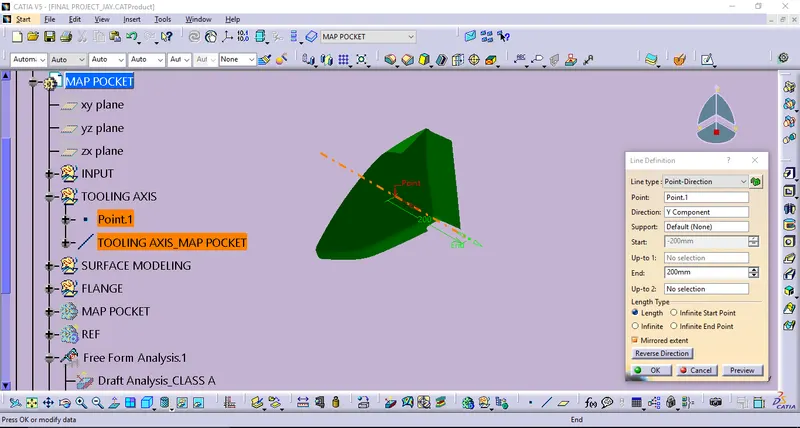
STAGE_1: TOOLING AXIS CREATION
The Tooling Direction which one is the direction that the mold pulls apart. The mold is built in two separate halfes of like Cavity side and the Core side. The Core pulls out from the Cavity along with the certain direction which is called as Tooling direction or Tooling Axis.
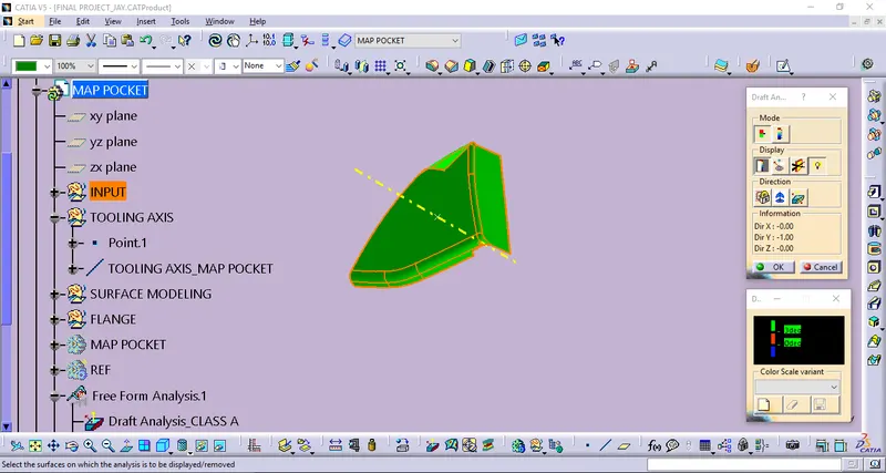
STAGE_2: DRAFT ANALYSIS FOR CLASS-A
By using of Feature Draft Analysis with the Minimum draft angle of 3 deg along with the above Main tooling axis. Thus the results shown here as following as,
STAGE_3: SURFACE MODELING
STEP_1: CLASS-B SURFACE CREATION
Class-B surface, In which can be easily defined as the thickness of the part and it is not visible which is inside surface of the Class-A. For the following plastic component thickness as 2.5 mm from the Input data. While offseting Class -A for 2.5 mm of thickness directly by applying Offset surface definition.
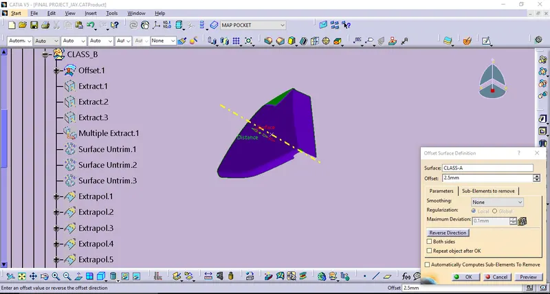
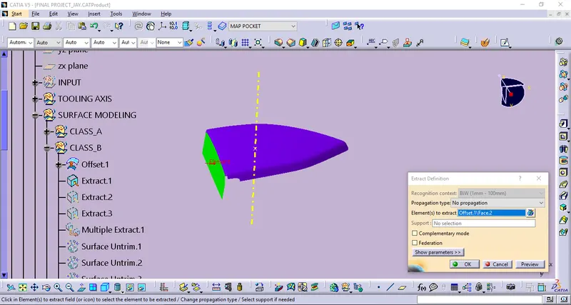
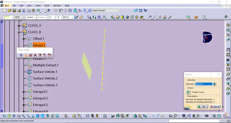
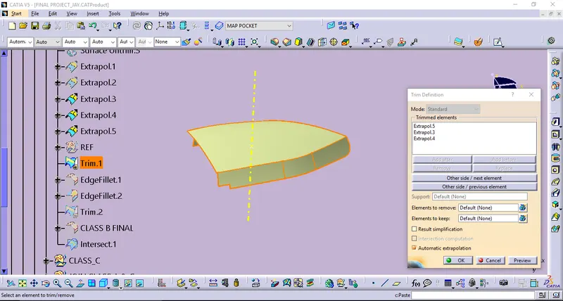
Commands used: Offset surface, Extract & Multi extract, Untrim, Extrapolate, Trim, Edge fillet etc., And some of its solvings are,
By using of Offset surface definition.
By using of Extract definition.
By using of surface Untrim definition.
By using of Trim definition.
By using of Edge fillet definition.
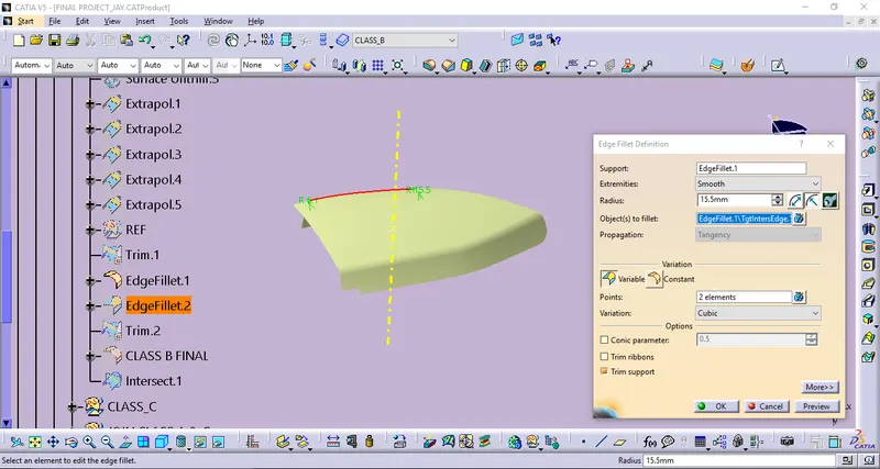
By using of Trim definition.
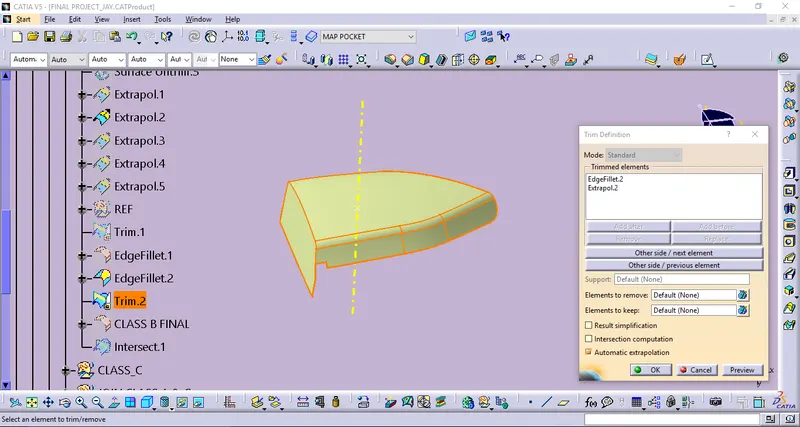
STEP_2: CLASS-C SURFACE CREATION
By defining the Class-C surface with respect to the Class-A surface. From the Class -A surface edge boundaries used to performed to create the Class-C surface. And the some of its workings are,
Commands used: Swept surface(type-2) with drfat direction , Swept surface(type-2) with ref surface, Boundary, Curve smooth, Extrapolate, & Trim.
By defining Swept surface along with the guide & reference surface. And some of its solvings are,
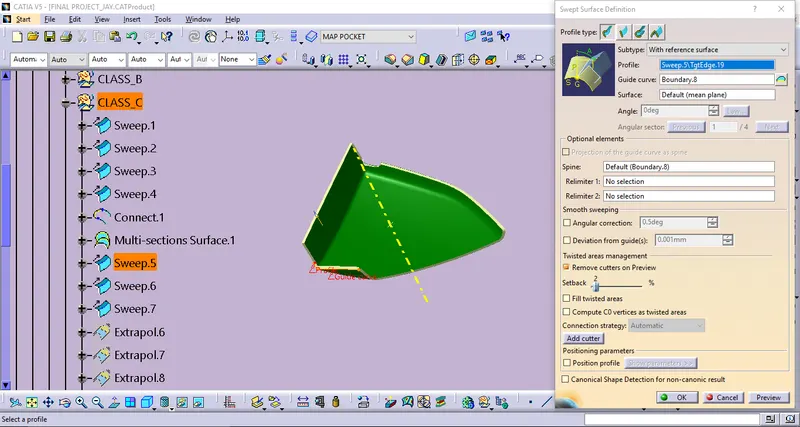
By using of Join Definition.
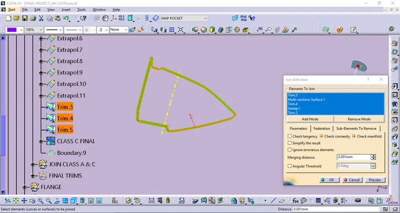
STEP_3: JOIN CLASS-A & C
By using of Join Definition.
STEP_4: FINAL TRIMS
By using of Trim Definition.
STAGE_4: SOLID PART_CLOSE SURFACE
By using of Close surface Definition.
4. BOTTLE HOLDER
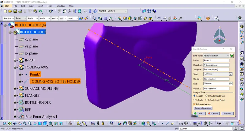
STAGE_1: TOOLING AXIS CREATION
The Tooling Direction which one is the direction that the mold pulls apart. The mold is built in two separate halfes of like Cavity side and the Core side. The Core pulls out from the Cavity along with the certain direction which is called as Tooling direction or Tooling Axis.
STAGE_2: DRAFT ANALYSIS FOR CLASS-A
By using of Feature Draft Analysis with the Minimum draft angle of 3 deg along with the above Main tooling axis. Thus the results shown here as following as,
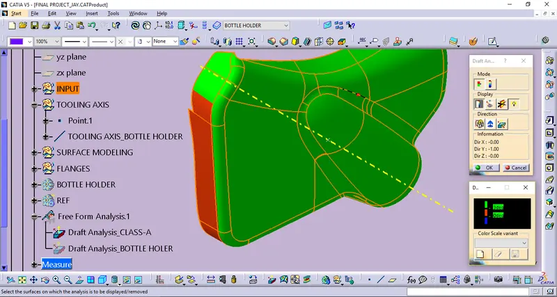
Noted: From the Draft Analysis results, In Class-A has less than 3 deg of draft angle over there for the further proceeding as of that above same Class-A used to creating this component.
STAGE_3: SURFACE MODELING
STEP_1: CLASS-B SURFACE CREATION
Class-B surface, In which can be easily defined as the thickness of the part and it is not visible which is inside surface of the Class-A. For the following plastic component thickness as 2.5 mm from the Input data. While offseting Class -A for 2.5 mm of thickness directly by applying Offset surface definition.
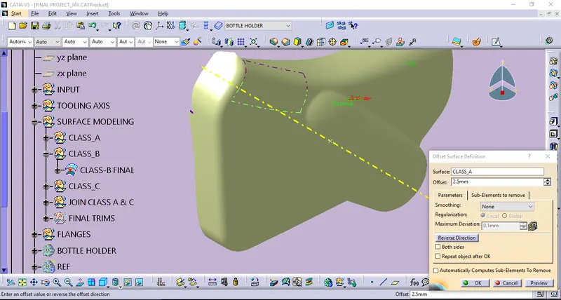
STEP_2: CLASS-C SURFACE CREATION
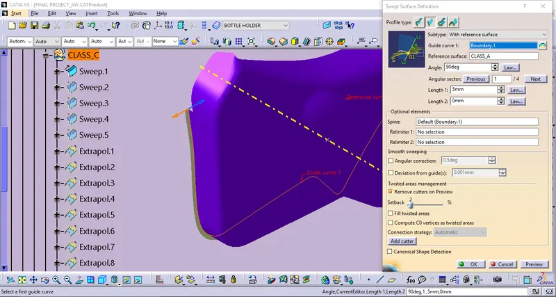
By defining the Class-C surface with respect to the Class-A surface. From the Class -A surface edge boundaries used to performed to create the Class-C surface. And the some of its workings are,
Commands used: Swept surface(type-2) with drfat direction , Swept surface(type-2) with ref surface, Swept surface(type-1) with ref surface along with the profile and guide curve, Boundary, Curve smooth, Extrapolate, & Trim. And some of its solvings are,
By defining Swept surface along with the guide & reference surface.
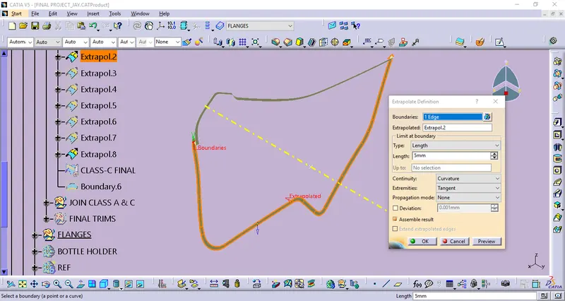
By using of Extrapolate Definition.
By using of Trim Definition.
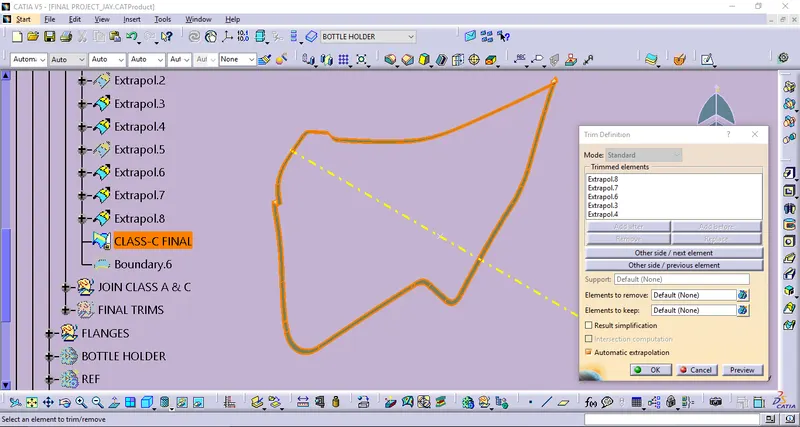
STEP_3: JOIN CLASS-A & C
By using of Join Definition.
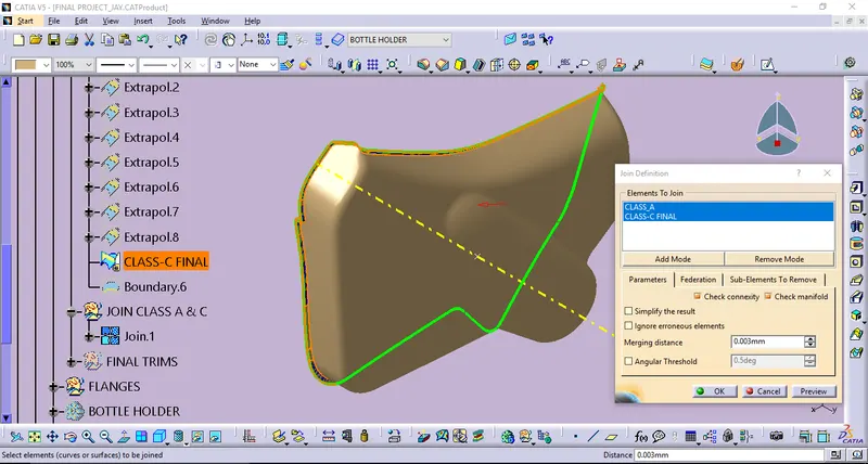
STEP_4: FINAL TRIMS
By using of Trim Definition.
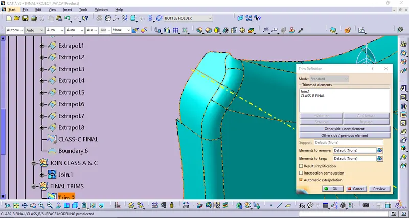
STAGE_4: SOLID PART_CLOSE SURFACE
By using of Close surface Definition.
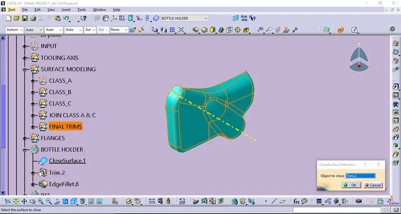
DOOR TRIM_ENGINEERING FEATURE CREATIONS:
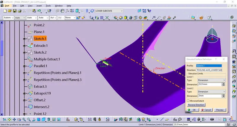
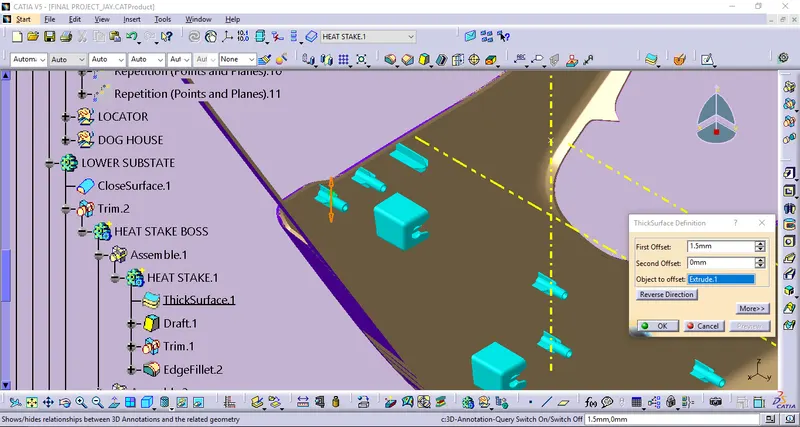
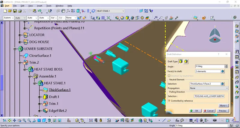
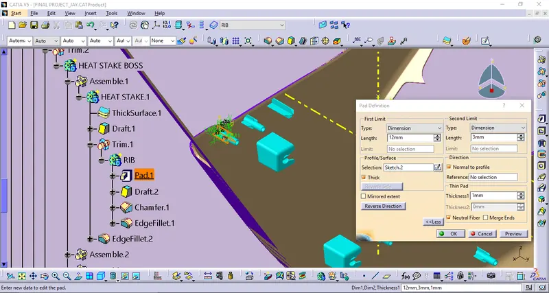
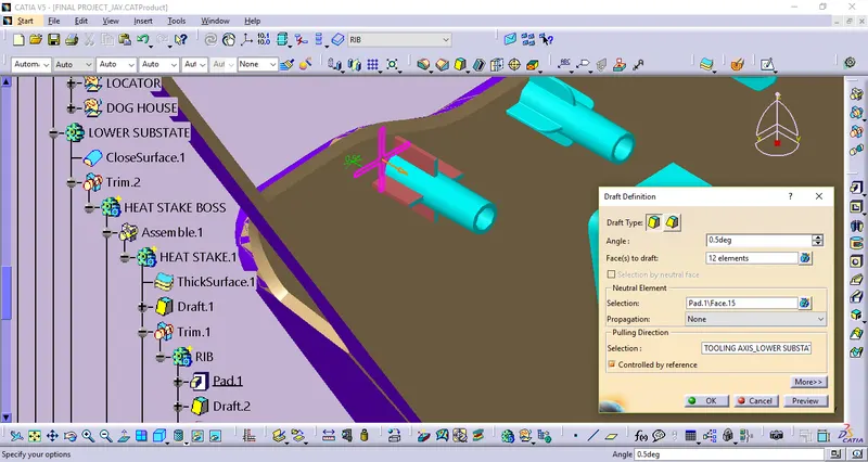
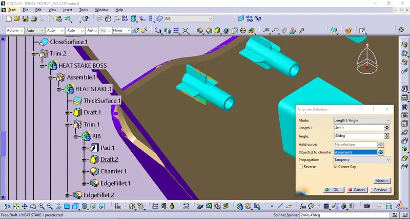
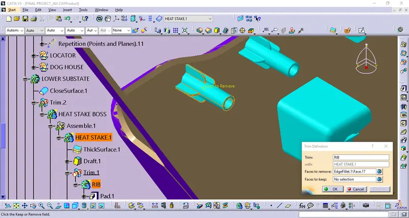
1. HEAT STAKE BOSSES :
- Heat stakes are used in thermoplastics to assemble two parts together by locally heating and cooling the plastic material and allowing it to reform itself and act as a joint for the two materials.
- And it become creates the permenent join over the two or more plastic components while joing process.
- One of the major design consideration while designing the heat skates is the height of the heat skates. It should always keep less than the height of the locators.
Working of Heat stakeboss Creation,
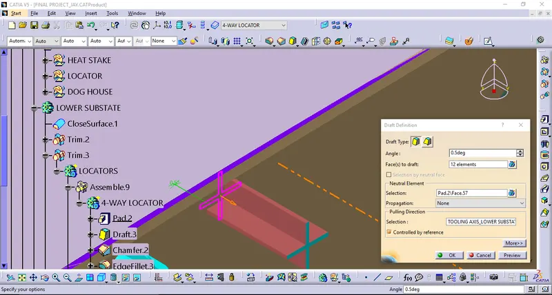
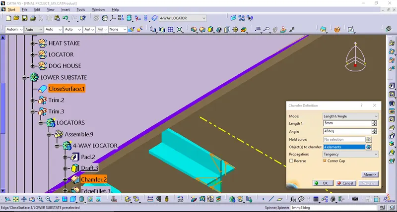
2. LOCATORS:
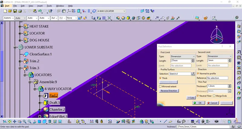
- The main purpose of locators is to facilitate proper locking of two components together while assembling and arrest the maximum degrees of freedom possible.
- These locators are similar to guide pins provided in mould.
- The two types of locators used are two way locator and four way locator. And here we are using 4-way locators.
Workings of Locator creation,
3. FLANGES :
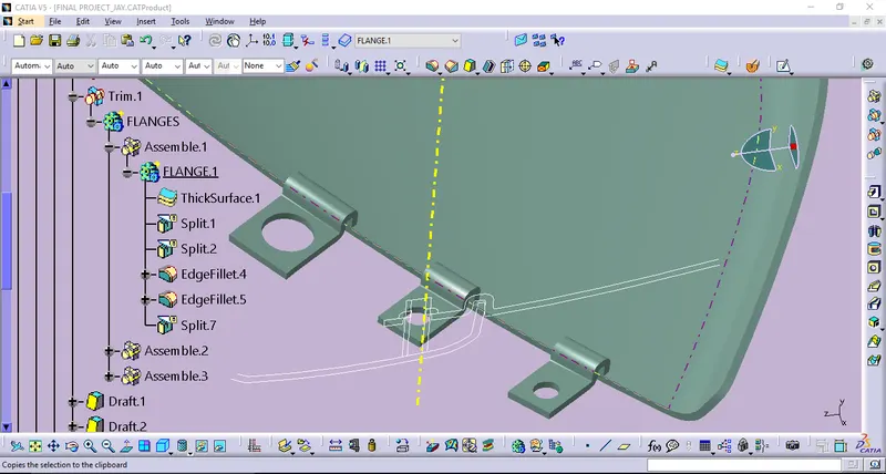
Flanges were created by using with the reference dimensions from the given master sections. And the purpose of the flanges were to provide slots for the heat stakes and locator which are required to assemble the two components together and constraint.
Workings on Flanges,
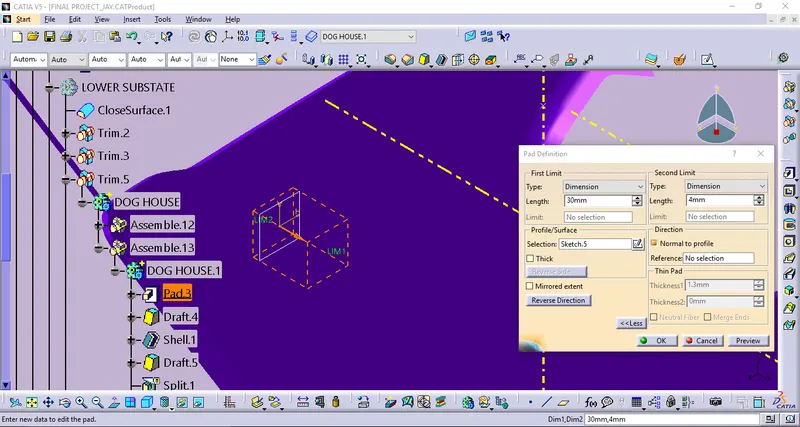
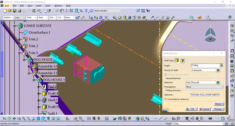
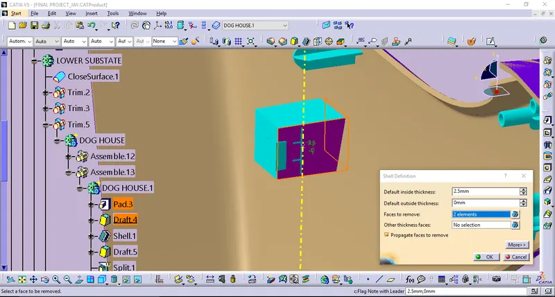
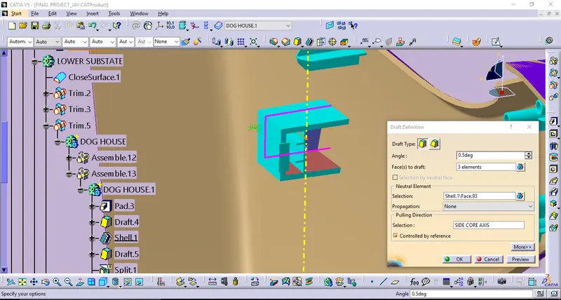
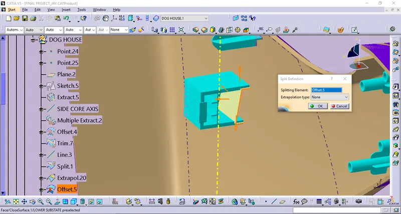
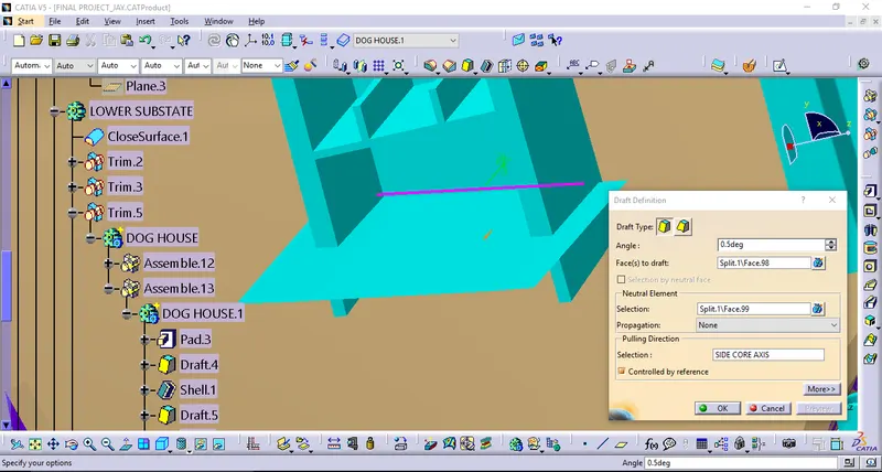
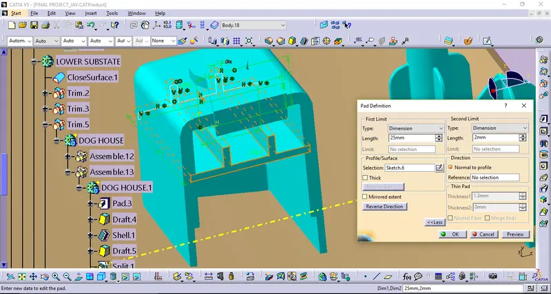
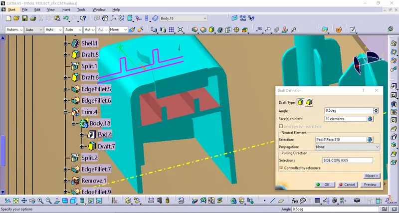
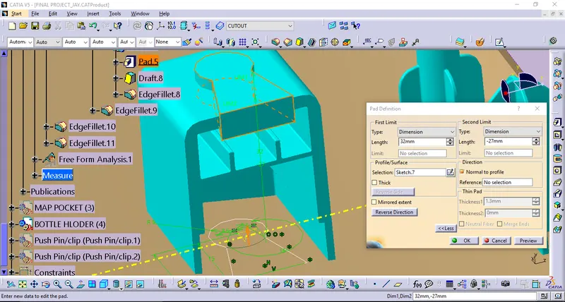
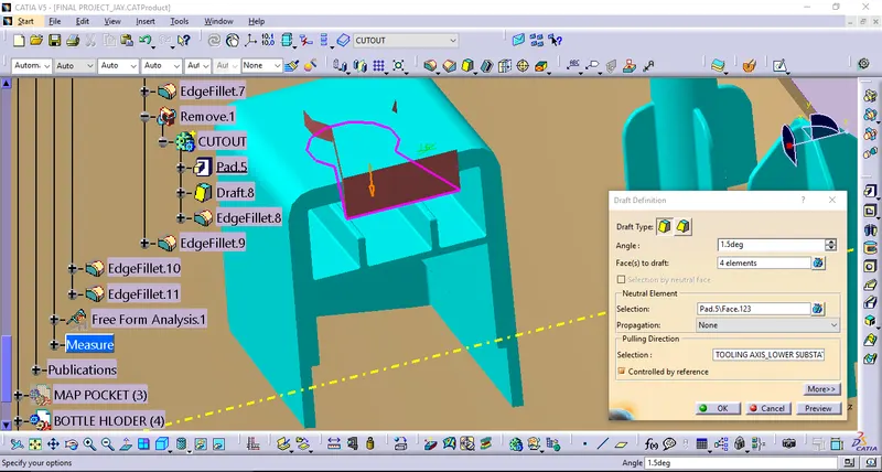
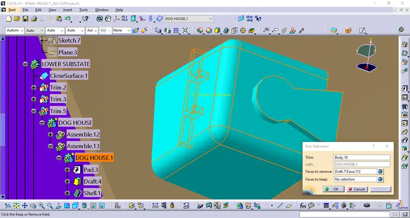
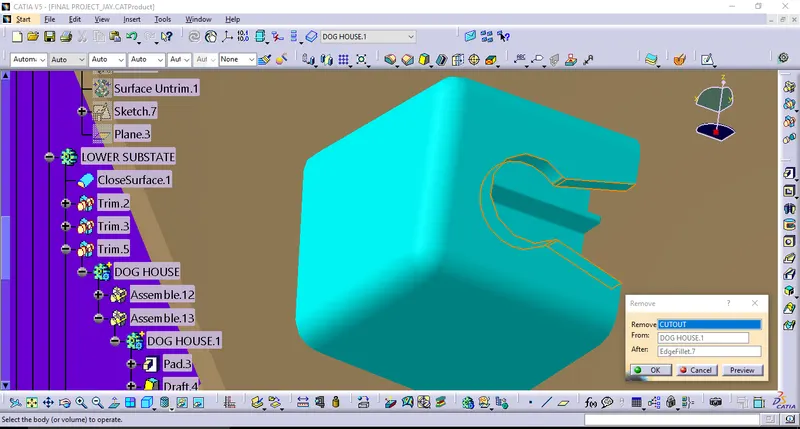
4. DOG HOUSE:
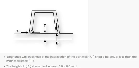
- The two main purposes of a dog house are to avoid sink marks and to house various other engineering features like screw boss, locators, push clips etc.
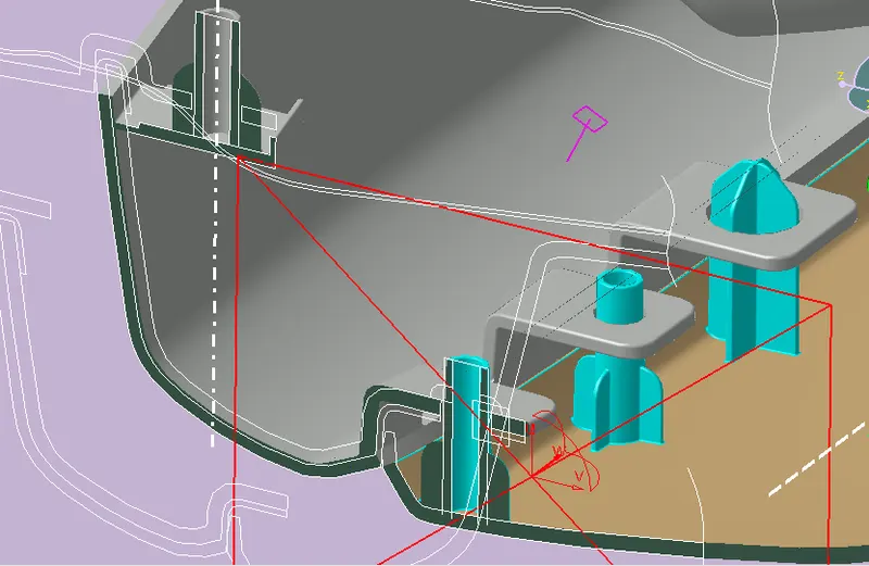
- In this case, the dog house is designed to house the push clips and here thus the push clips are assembled over the dog house mountings for using to attaching plastic componets over the sheet metal compnent.
- The dog house should follow certain design rules which are stated below
Workings of Dog House creations,
DOOR TRIM_DRAFT ANALYSIS FOR FINAL COMPONENTS
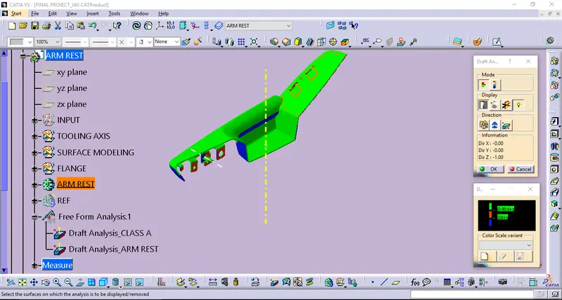
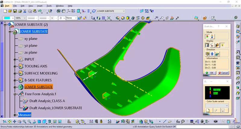
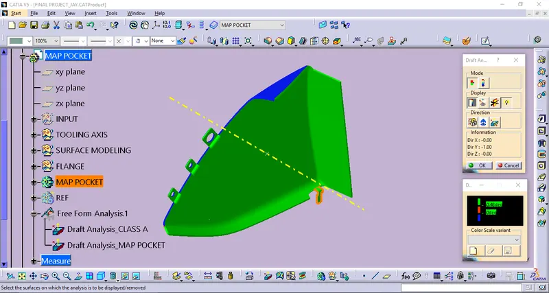
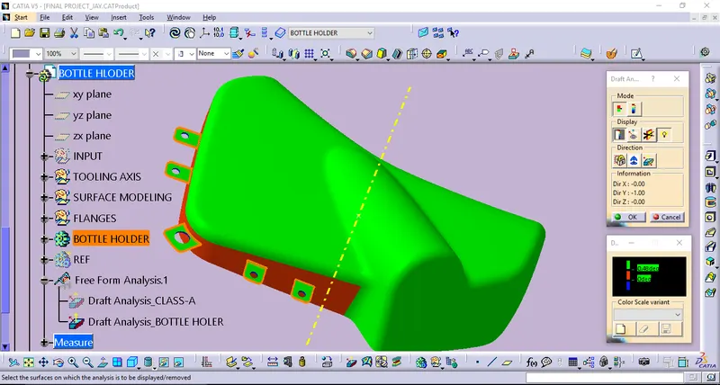
Draft analysis for the final component along wint the main tooling axis wint the draft angle of 0.48 deg. And the results of following components are,
1. DRAFT ANALYSIS OF ARM REST
2. DRAFT ANALYSIS OF LOWER SUBSTRATE
3. DRAFT ANALYSIS OF MAP POCKET
4. DRAFT ANALYSIS OF BOTTLE HOLDER
DOOR TRIM_FINAL ASSEMBLY
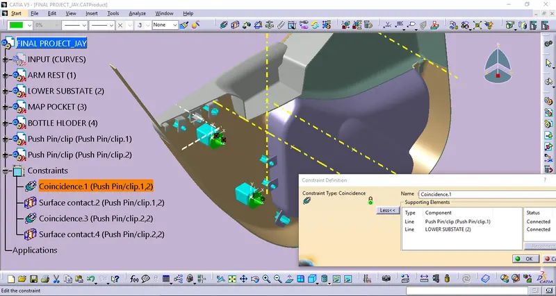
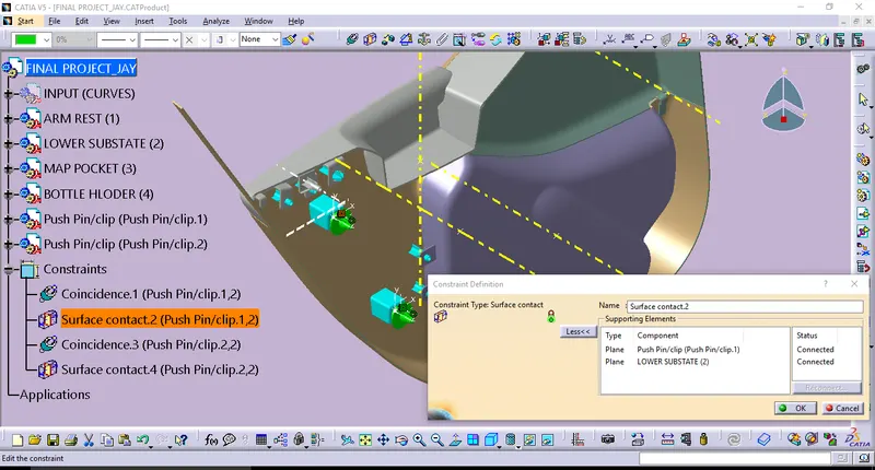
Thus the final assembly of the following door panel in which is the push pin clips placing into the respective dog house slots. Using the dog house central axis and the axis of the push pin coincident relation was given. After which, using contact constraint the push clips were made to sit in the dog house slot as required.
By defining of Coincidence constraint.
By defining of Surface contact constraint.
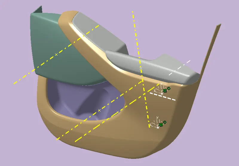
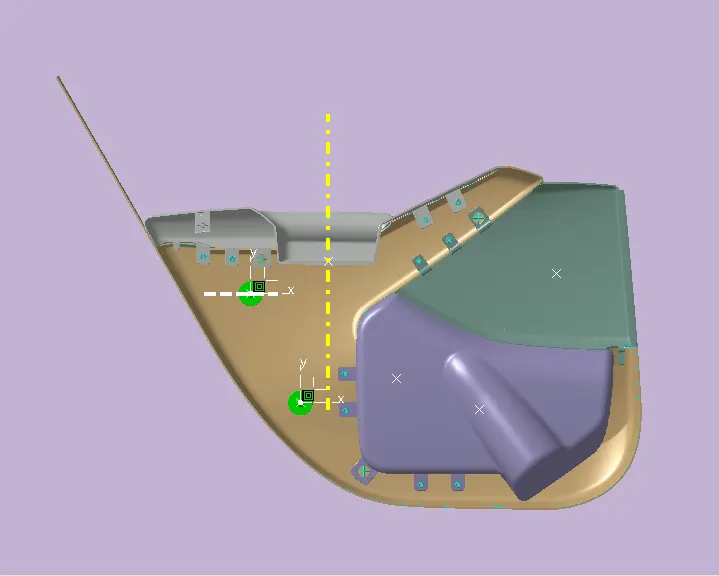
VIEW ORIENTATIONS_DOOR TRIM
ISO VIEW
SIDE VIEW
SECTION VIEW
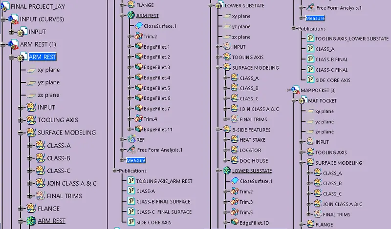
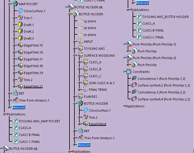
TREE STRUCTURE:
CONCLUSION:
Thus the design developmet of Door Trim Panel along with the Master Sections plastic Component successfully created by using CATIA v5.
And the followings also,
Tooling axis for the given Class-A Surface and its Draft analysis to be completed.
Engineering Features (B side Attachment Features) of the component created by following the design guidelines.
Draft analysis for both the Main Tooling axis and Side Core Axis of the Final component has performed.
Noted:
Draft Analysis results some of itself not cleared due to that Class-A (Arm rest & Bottle Holder).
Applying Material details & the Parting line Creations not yet done here and as of that discussed over the Support session.