Week 12- Final project
DOOR TRIM PANEL
AIM:
- The Project's is to construct half of the Door Trim Panel in catia-V5 using the very same Class-A Surface that has been provided.
ABSTRACT:
- An overview of design principles and methodology used to finished plastic product provided in this study. A draft analysis report covering every Class-A surface, with the exception of the steps required to create the Class-B and Class-c surface, is also included.
APPROACH:
Our basic approach to create a plastic model from class-A surface should be:
- Run Draft analysis
- Make Tooling axis
- Make class-B surface
- Make class-C surface
- Trim all together and make it solid
CLASS-A SURFACE:
- In the automobile industry, many teams work on different component; a car' design, for instance, is not created solely by one designer. The work of creating various components is divided among numerous teams and every industry department operates under this. Class-A surfaces created by class-A designers using different applicatons, such as Autodesk Alias, are provided to us for this project. This is an attractive surface, and creating a continous, well flowing surface model requires a great deal of time,effort and experience. This is the major reason why, when we get this as input we are not allowed as a plastic designer to make any improvements in the class-A surface. Rather, it should be brought to the attention of the seniors which later is conveyed to the concerned team and taken care of.
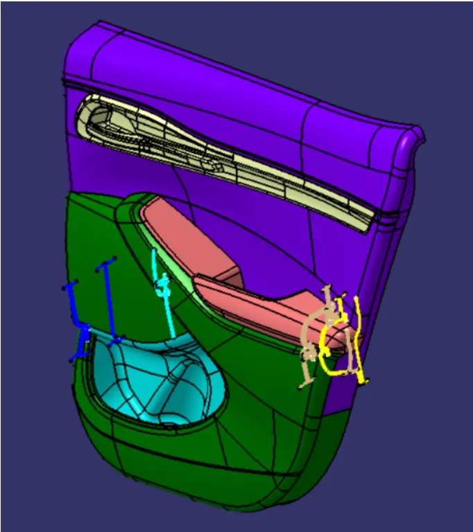
fig(1)
TOOLING AXIS:
- The axis along which the cavity and core open and close is known as the Tooling axis. Determining the tooling axis early in the component design process is crucial since it is primary element that enables us to perform a preliminary analysis on Class-A and determine whether further action is necessary. The Class-C surface and the draft to the components are delivered along the tooling axis, which is also the direction for later stages.
- In this model we have a tooling axis in the perpendicular direction to the entire door trim that is y- direction in the model. It is very evident that switch bezel will require side core, so another tooling axis is made specifically for switch bezel. Apart from these two tooling axes we also have a side core tooling axis for dog house.
DRAFT ANALYSIS:
- Our first step before starting the model should always be to check is the surface has enough draft that it will not create any problem while ejecting from the mold. This seems like a big task as we have to foresee something that will come at very later stage. But this is done by small process called Draft Analysis. This analysis tells us whether our component will be safely ejected in the tooling axis we have provided. Some components require side core axis where there are under cuts, holes or projections on side walls, so for this we need different tooling axis and a different analysis is required to check those areas. Draft analysis shows color codes which are defined by user for different values which also are defined by user. These colors help us to analysis if the component is clearing the analysis and we are good to go ahead or not. In case the component fails the analysis for the Class-A surface then we have to submit draft analysis report to the higher authority so that the surface of the component can be improved. Failing analysis simply means that the component does not have the required draft value it must have. In case our solid model which we develop, fails the analysis at some parts then we to correct it ourselves.
- We have to make sure that our entire model is green which means it is clearing the analysis. So we have to run analysis for class-A, solid model and other B-side features as every single component, regardless of its size should be ejected safely from the core.
DRAFT ANALYSIS ON CLASS-A SURFACE:
- LOWER SUBSTRATE:
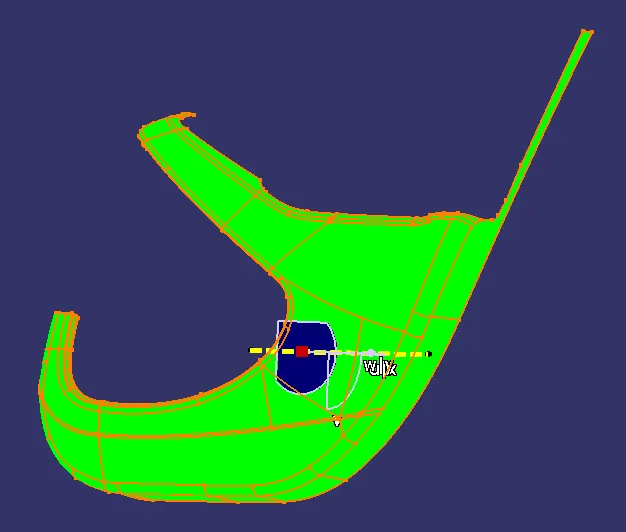
fig(2)
- LOWER MAP POCKET:
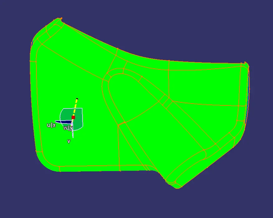
fig(3)
- UPPER MAP POCKET:
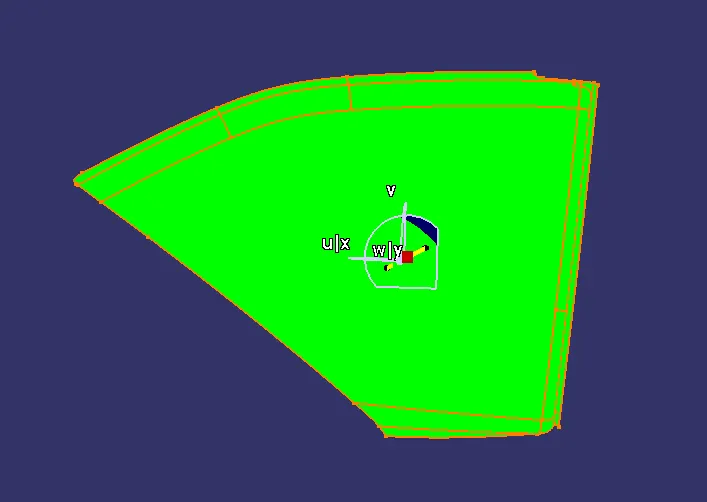
fig(4)
- ARM REST:
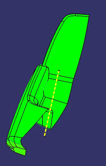
fig(5)
DESIGNING METHODOLOGY:
- ARM REST:
- After draft analysis, some surfaces are folded inside so we will need a side core axis for the creation of this kind of surfaces we need side mold for the creation of the model. Now we will create the class-B surface by creating offset of 2.5mm as it was taken from the master section that is provided with the main surface.
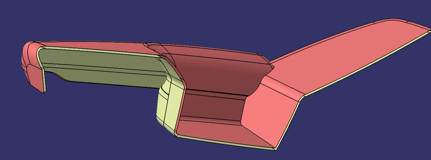
fig(6)
- The above surface is class-A surface and below surface is class-B surface which is offset to 2.5mm from class-A. We do had some irregular surfaces to fix which we did fix using multi-section solid and fill command. After, creating the class-B surface we had to extrapolate the surface so that we can make a trim between class-C and class-B surface. Now we created the class-C surface in multiple parts and then join them. As the boundary had so many turns and fillets, we had to create the class-C surface in parts and then join them together.[fig(7)]
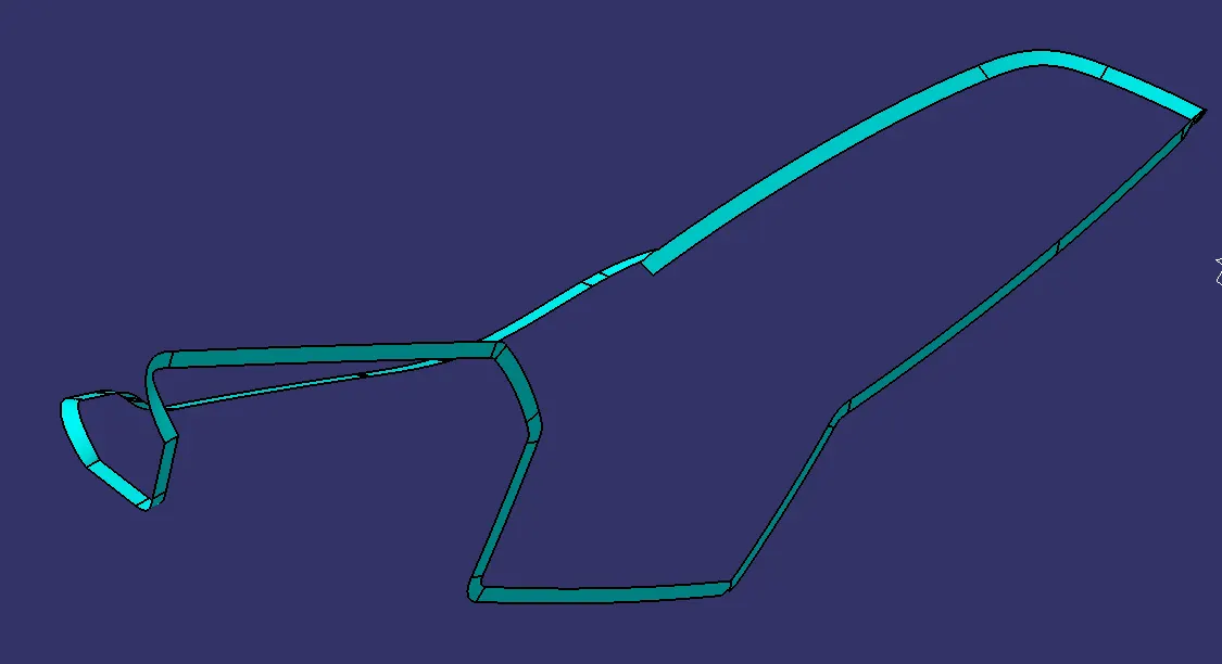
CLASS-C SURFACE -[fig(7)]
- Afterwards, join Class-A, B and C surface together. Now we create a closed body and then performed the draft analysis on the same.
- Closed Body:
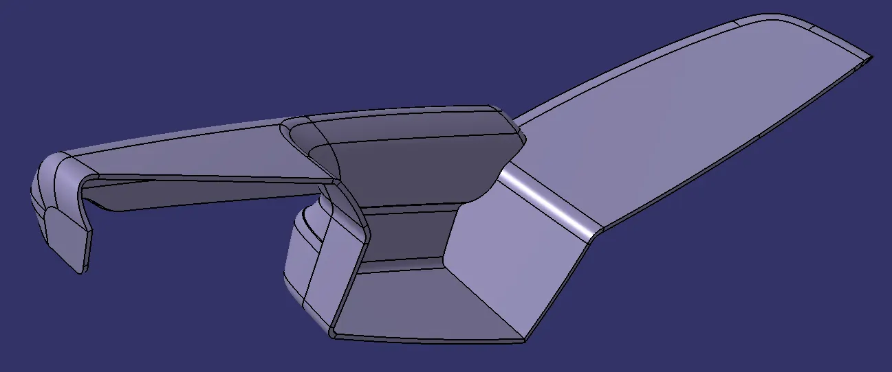
fig(8)
- Draft Analysis:
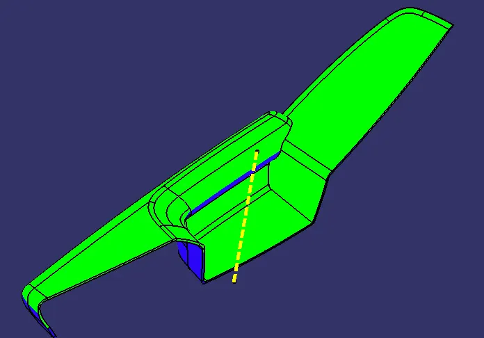
fig(9)
- In fig(9), Draft analysis of closed body is same as that of class-A surface. So we need some side core for creation of this kind of surface.
- UPPER MAP POCKET:
- Class-A Surface:-
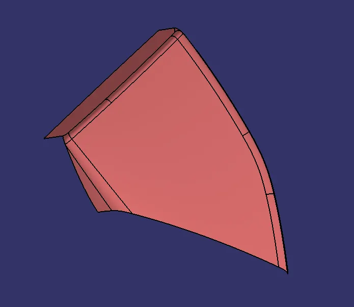
fig(10)
- Draft Analysis of Class-A surface as shown in fig(4).
- Class-B surface:-
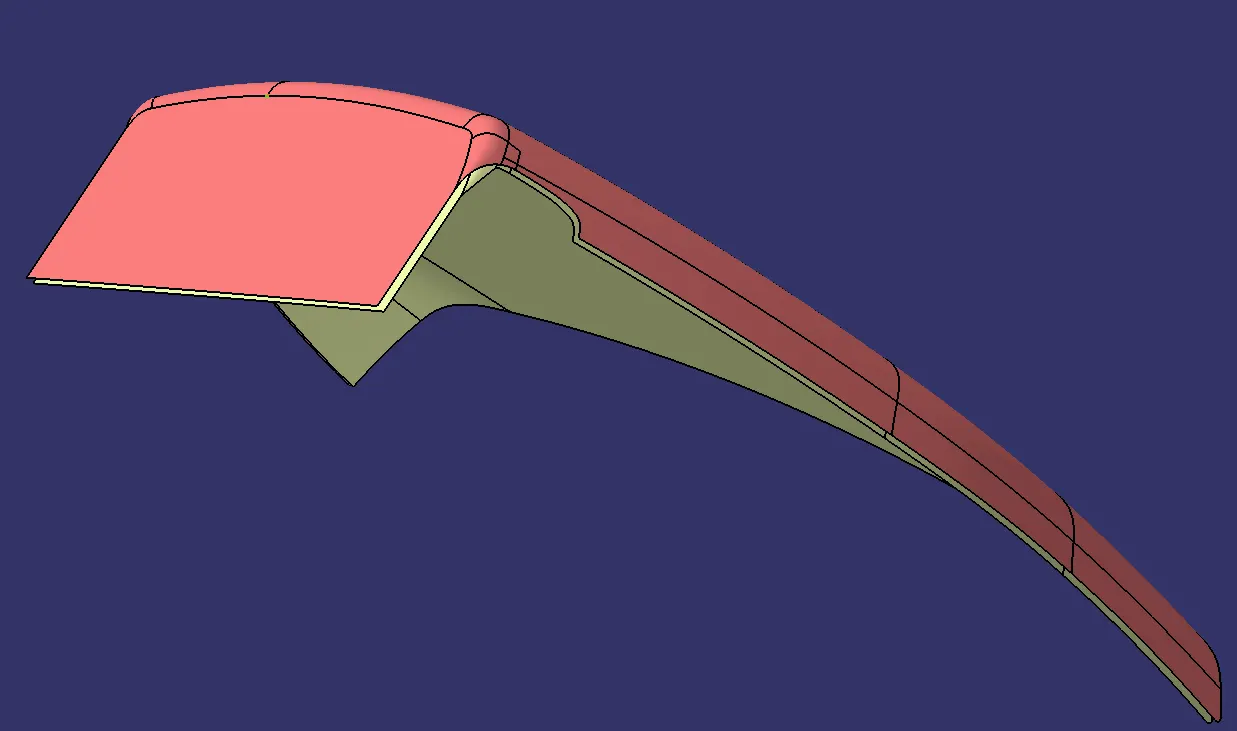
fig(11)
- Class-C surface:-
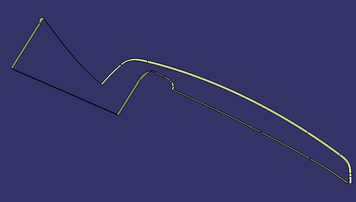
fig(12)
- Closed body:-
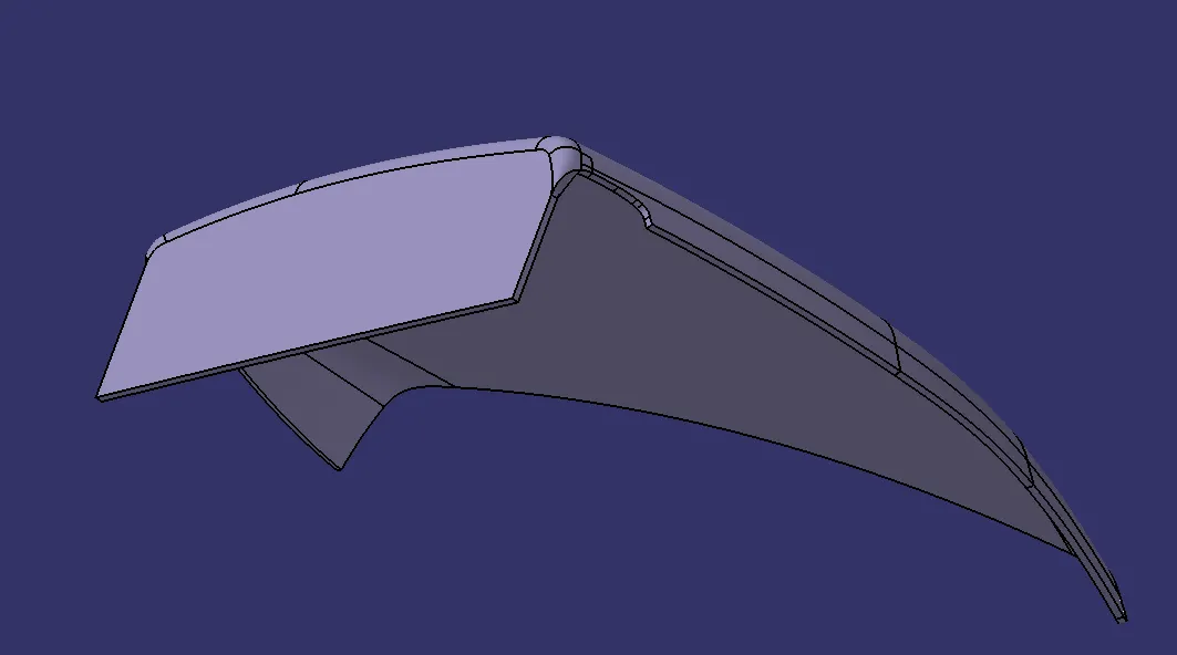
fig(13)
- Draft Analysis:-
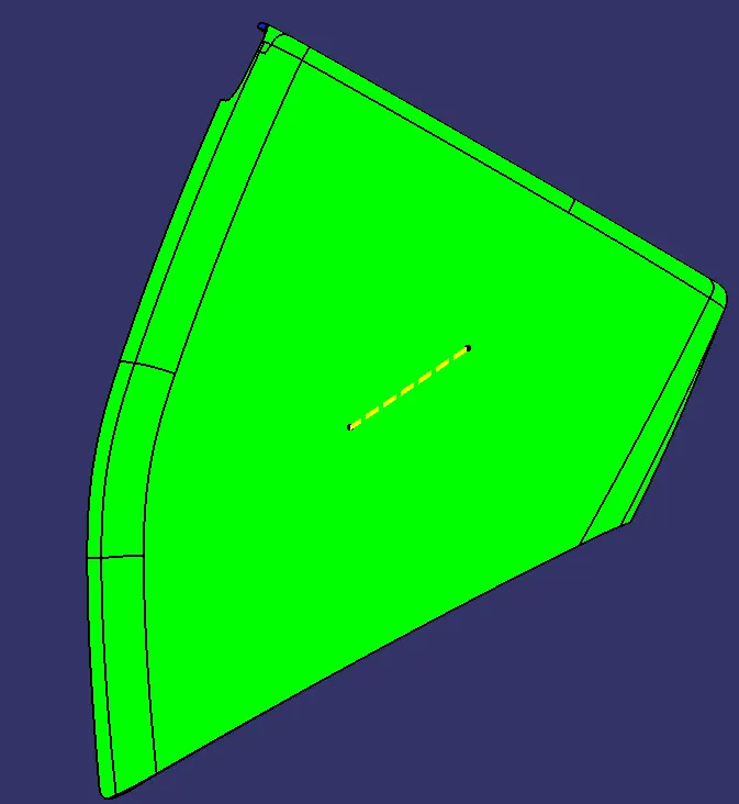
fig(14)
- LOWER MAP POCKET:
- Class-A Surface:-
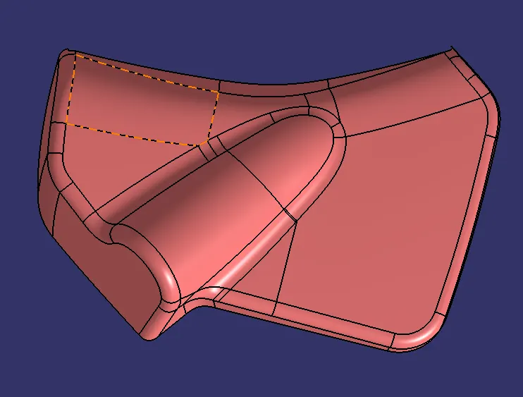
fig(15)
- Draft Analysis of Class-A surface as shown in fig(3).
- Class-B Surface:-
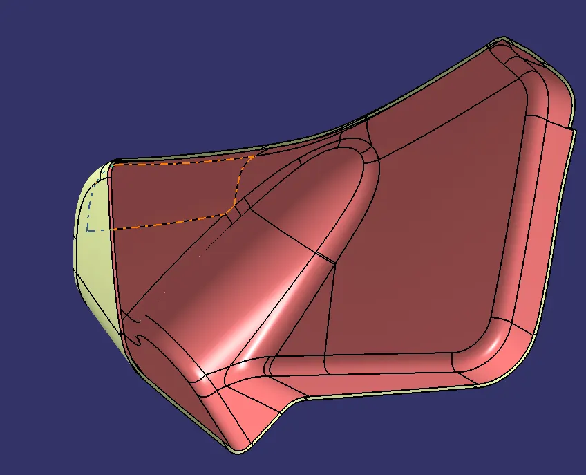
fig(16)
- Class-C Surface:-
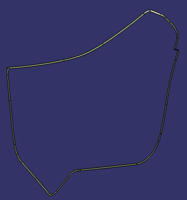
fig(17)
- Closed Body:-
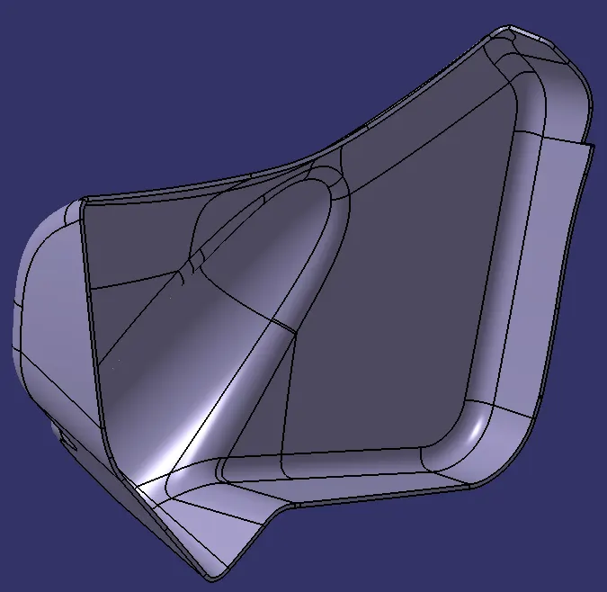
fig(18)
- Draft Analysis:-
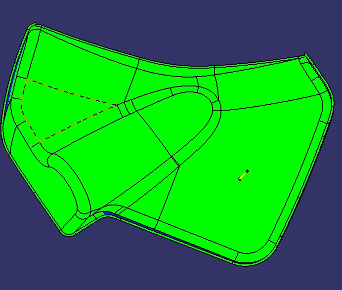
fig(19)
- LOWER SUBSTRATE:
- Class-A Surface:-
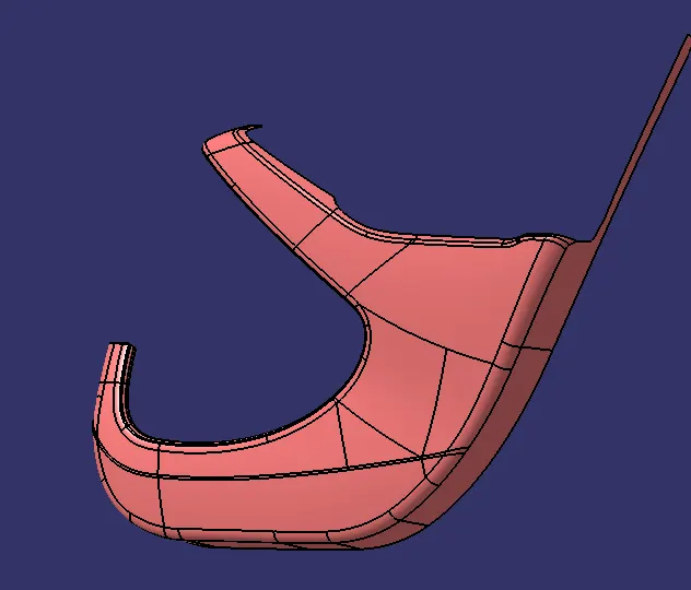
fig(20)
- Draft Analysis for Class-A Surface is shown in fig(2).
- Class-B Surface:-
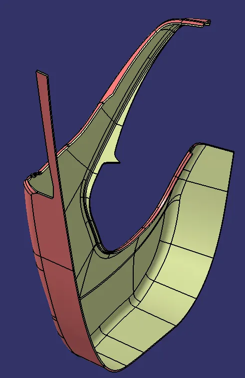
fig(21)
- Class-C Surface:-
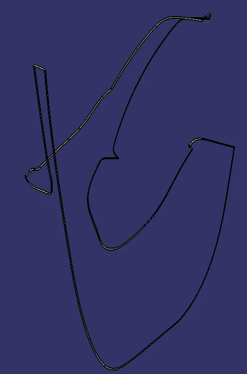
fig(22)
- Closed Body:-
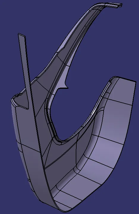
fig(23)
- Draft Analysis:-
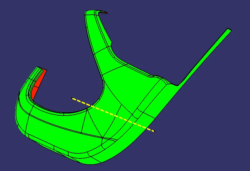
fig(24)
B-SIDE FEATURE:
- Dog House:-
- The primary purpose of the dog house is to avoid sink marks. Nevertheless, it also serves other purposes, for example, if mating portion is farther away and we are unable to put the screw boss at that height; instead, we must construct a dog house and install the screw boss on it. As a result, having a perpendicular screw boss and overcoming screw boss problem are both beneficial.
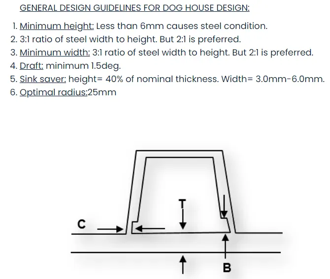
- However, for this material we made a dog house which mounts push pins on it. Every above design rules were followed while making the dog house.
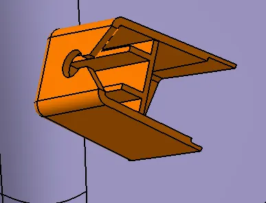
fig(25)
- Push clips are mounted on this dog house. But as the push clips are manufactured else where and is not in our area of concern so we have ignored the rules while making the push clips and made a general clip of similar shape in part design without following any rules.
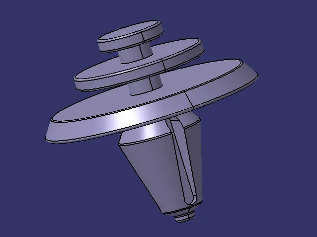
fig(26)
- HEAT STAKES:-
- Heat stakes are the feature which are used to join the two parts together. This is a permanent joint and is done by heat treatment. The heat stakes are given the draft angle of 0.5- degree. This heat stakes will join the lower substrate with Arm rest, Upper Map Pocket, Lower Map Pocket.
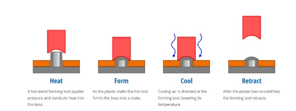
fig(27)- Heat Staking Process
ASSEMBLY:-
- The Assembly of the above surface is created by providing relevant constraints to the product, the assembly is shown below in different views.
- Isometric View:
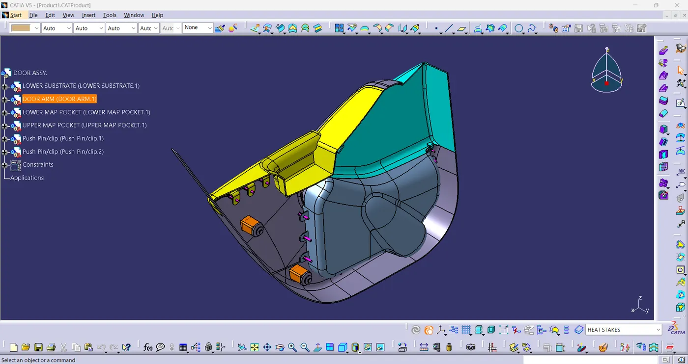
fig(28)
- Front View:
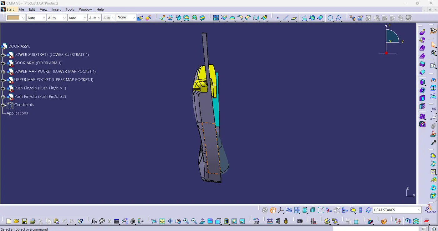
fig(29)
- Side View:
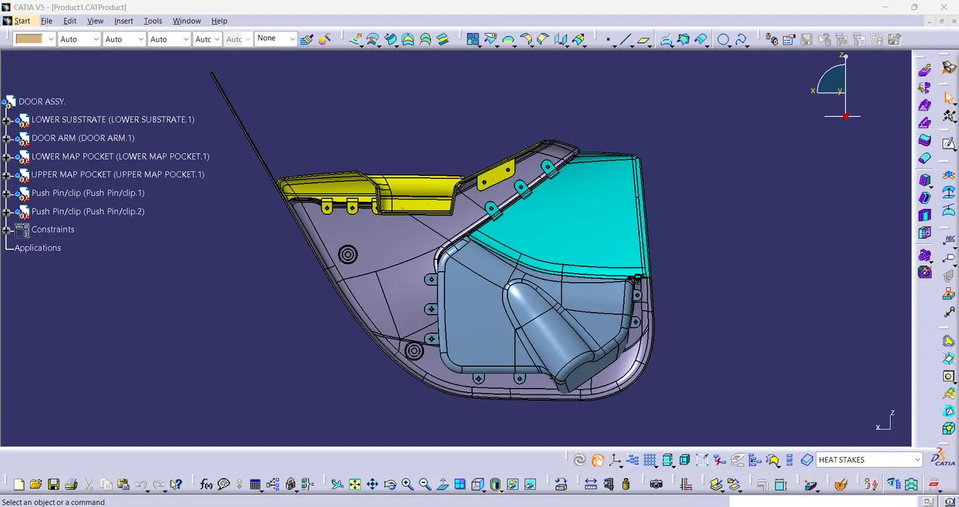
fig(30)
- Top View:
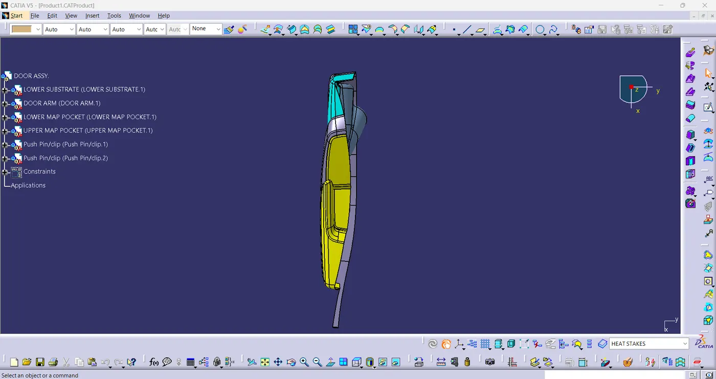
fig(31)
CONCLUSION:
- I have successfully created the assembly by following master section and design rules. Also constructed the Tooling axis, Class-B and Class-C surface of each part model. Draft Analysis perfomed on Lower Substrate, Lower Map Pocket, Upper Map Pocket and Arm Rest.