Week 12- Final project
AIM:
To develop the Door Trim panel
OBJECTIVE:
- Creation of CAD model considering the following inputs as like in OEM and tier1 companies
- Class A surface
- Nominal thickness: Refer to master sections
- Attachment strategy :
- Find an attachment strategy for the door panel complete work.
- Use Push pin with Dog house for Lower substrate – Door panel attachment
- Use heat stakes for part-to-part attachment
Output required:
- Create a thickened part using the master section for reference
- Create the mounting features as per design guidelines in the industry and with master sections
- Apply material details
- Draft analysis & Tooling analysis
- Creation of parting lines and checking tooling feasibility
SOFTWARE USED: CATIA
Let us look at how we have designed
INPUT:
CAD DATA is downloaded and Opened with CATIA.
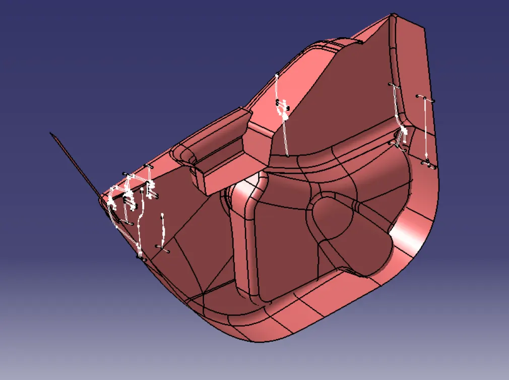
1- Armrest Part:
a. Class A Improvement:
First I have found that Class A that been given has open boundaries
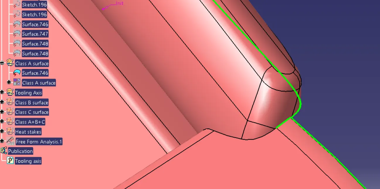
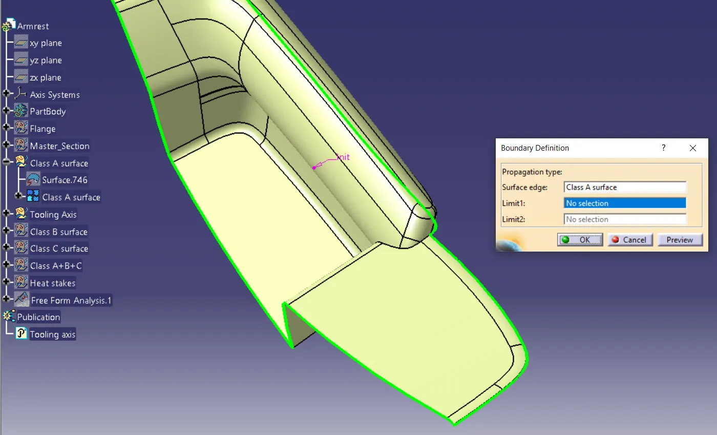
Class B is created by offsetting Improved Class A by 2.5 mm as per the master section.
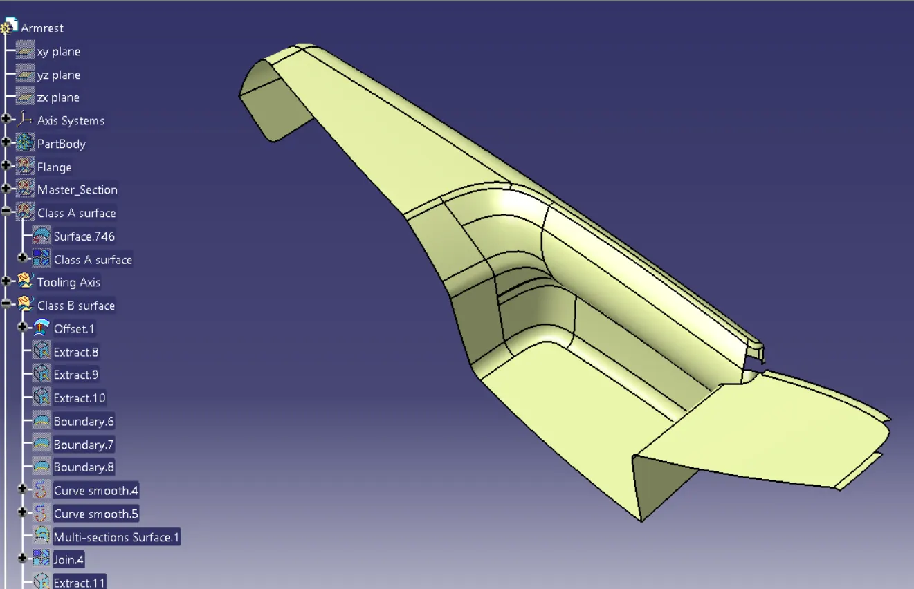
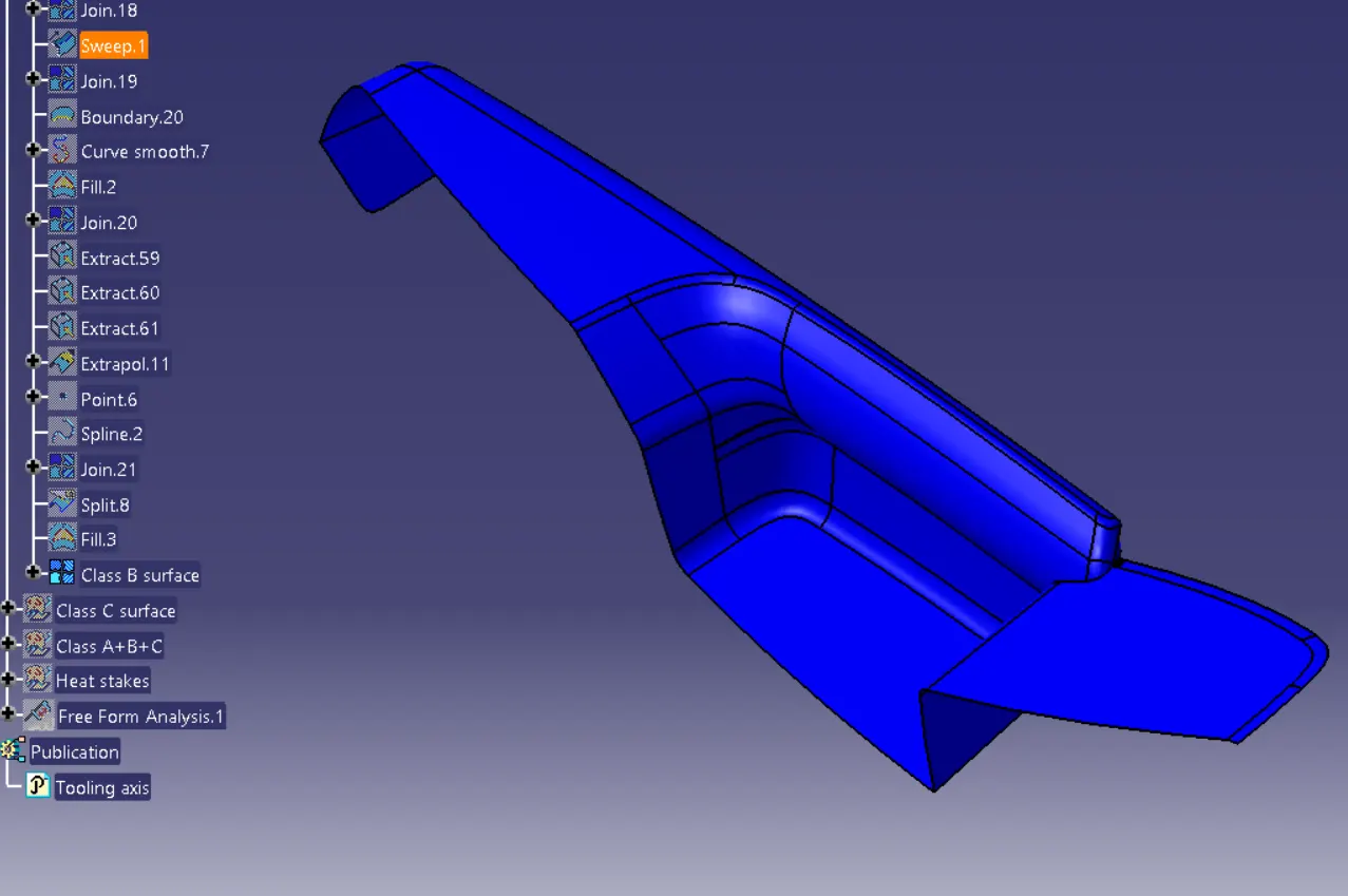
Class C is created by sweeping Improved Class A Surface and it has been trimmed with Class B Surface.
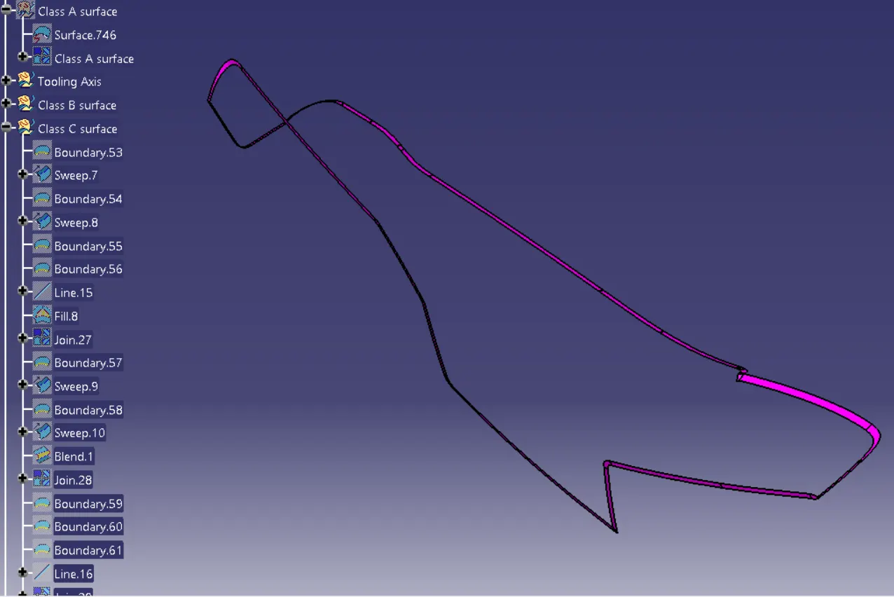
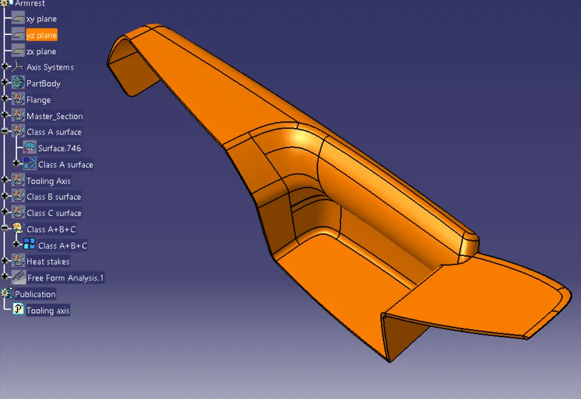
FINAL TRIM:
Join A and C surface.
Trim with the B surface.
TOOLING AXIS:
The tooling axis is defined as such all the features of the part can be manufactured easily. So here we followed the below steps to create the tooling axis.
- Tooling Axis created for the parts.
- Different ways of tooling axis creation are followed in OEM.
- Bisecting method, point, and direction are methods used here.
Main Tooling Axis is created in such a way to provide drafting.
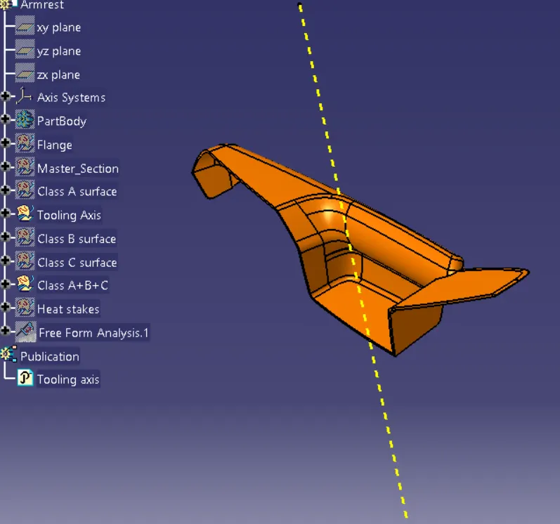
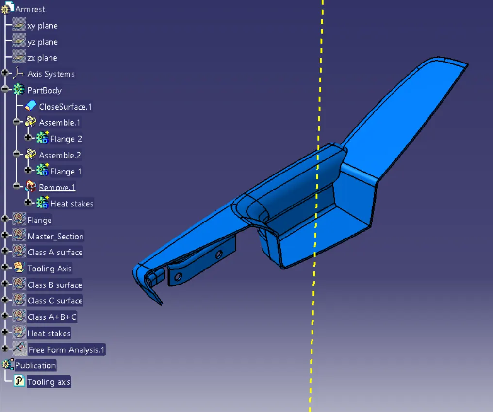
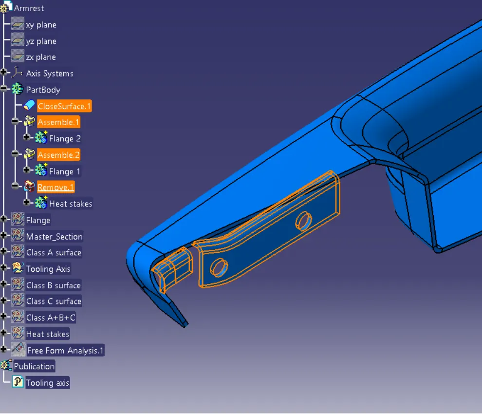
Close Body is created from the fully closed surface and then flanges & Heat stakes are created
Drafting Analysis:
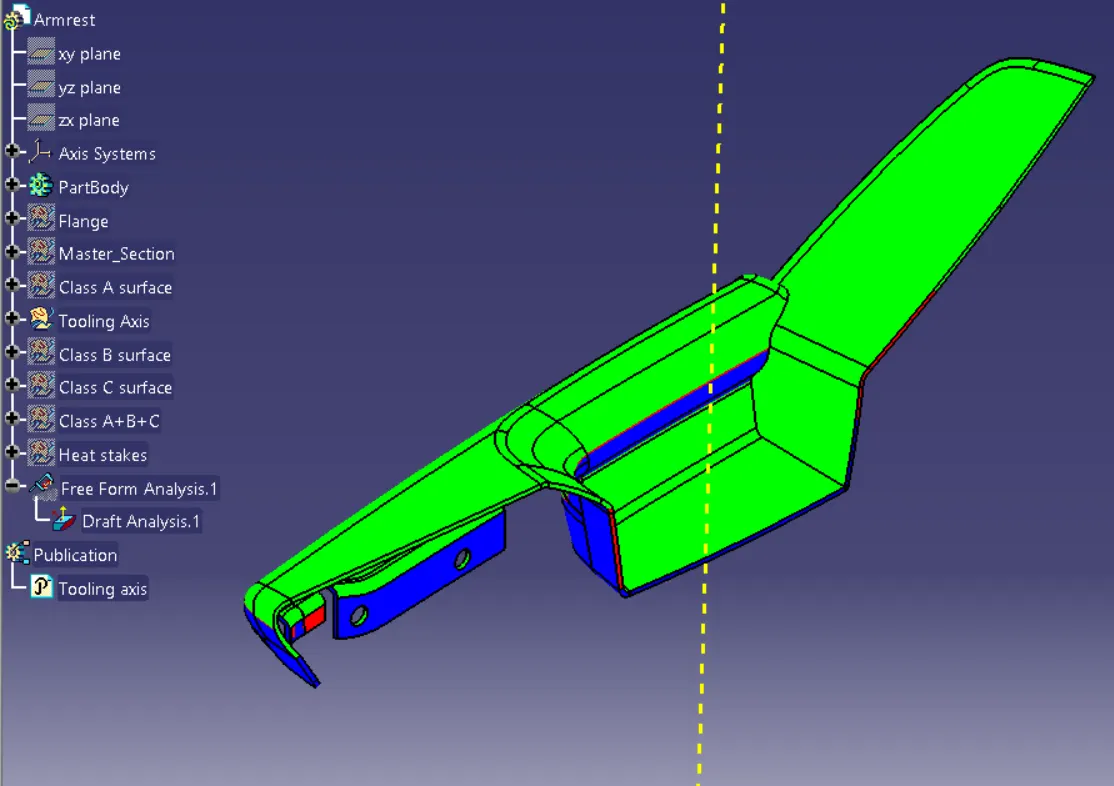
By applying drafting analysis at 3 Deg, we can see most bodies are been cleared. AsGreen is set at 3 degrees, blues is Zero, and less than Zero it is red colored.
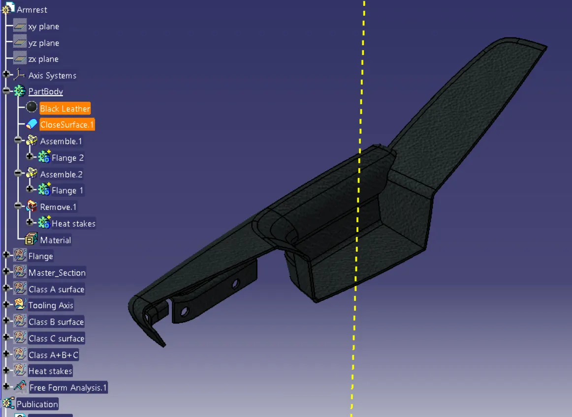
Applied material details as Black leather for the armrest body.
2- Lower Substrate:
Class A Surface was checked and found out it has perfectly closed boundaries, no further action is to be taken.
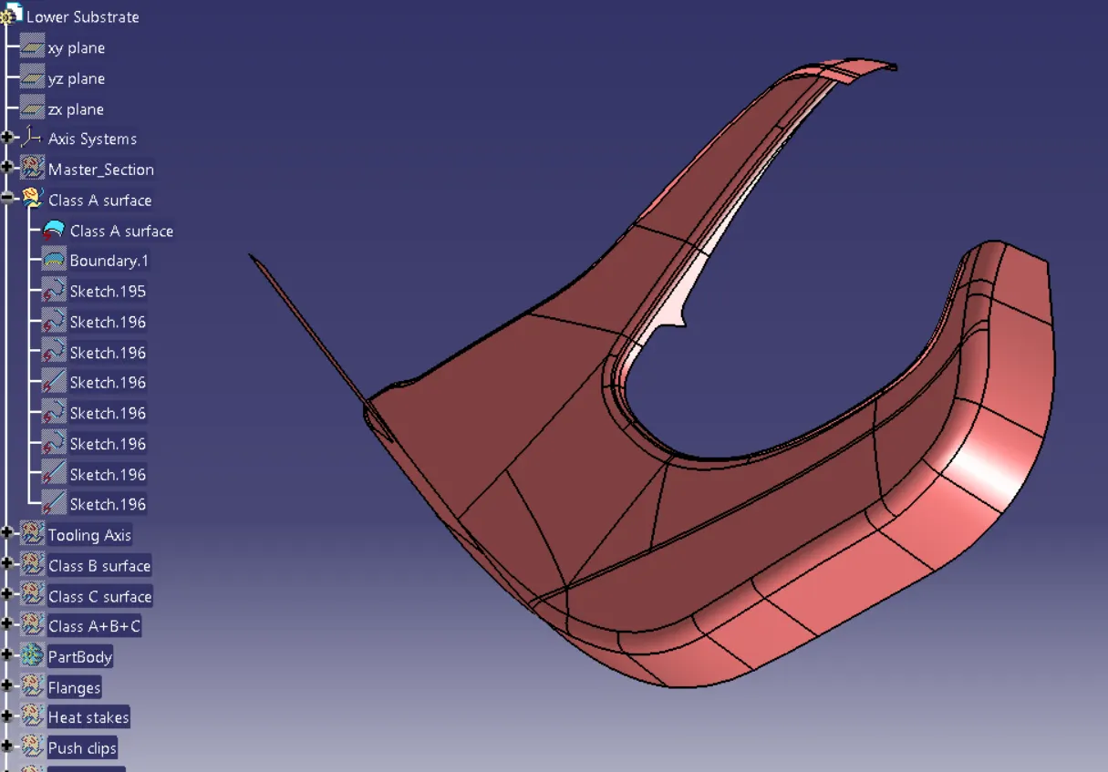
Class B is created by offsetting Improved Class A by 2.5 mm as per the master section
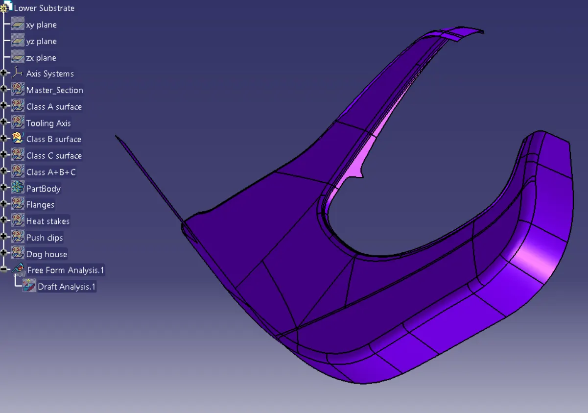
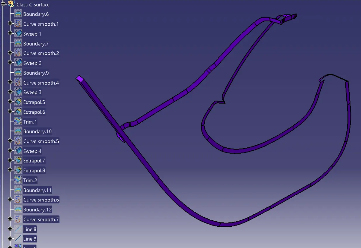
Class C is created by sweeping Improved Class A Surface and it has been trimmed with Class B Surface.
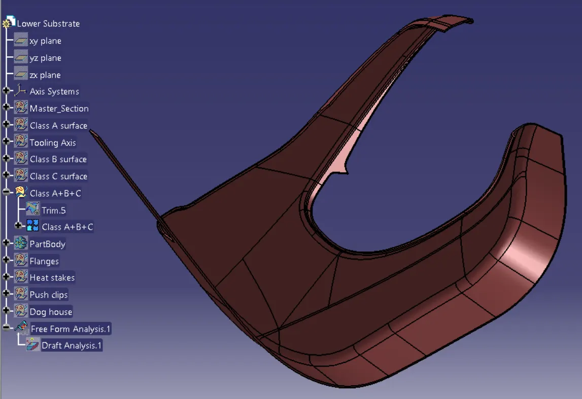
FINAL TRIM:
Join A and C surface.
Trim with the B surface.
TOOLING AXIS:
The tooling axis is defined as such all the features of the part can be manufactured easily. So here we followed the below steps to create the tooling axis.
- Tooling Axis created for the parts.
- Different ways of tooling axis creation are followed in OEM.
- Bisecting method, point, and direction are methods used here.
The Main Tooling Axis is created in such a way as to provide drafting.
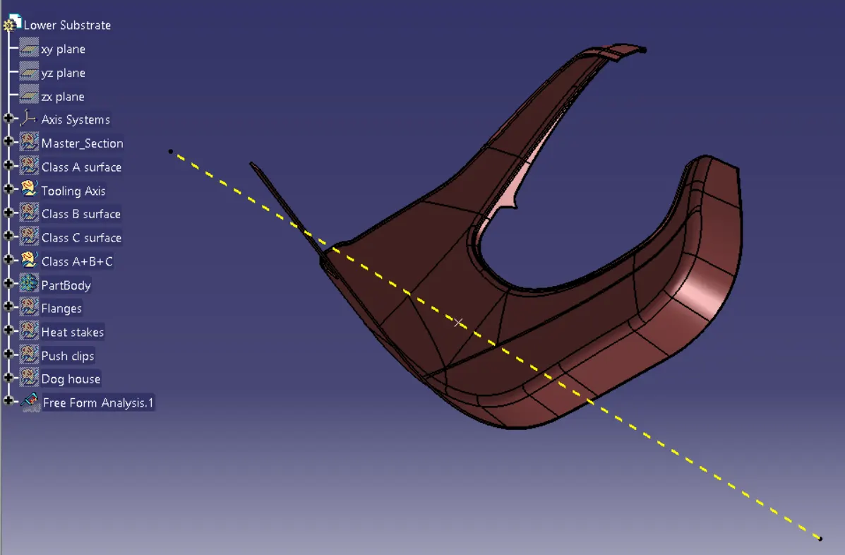
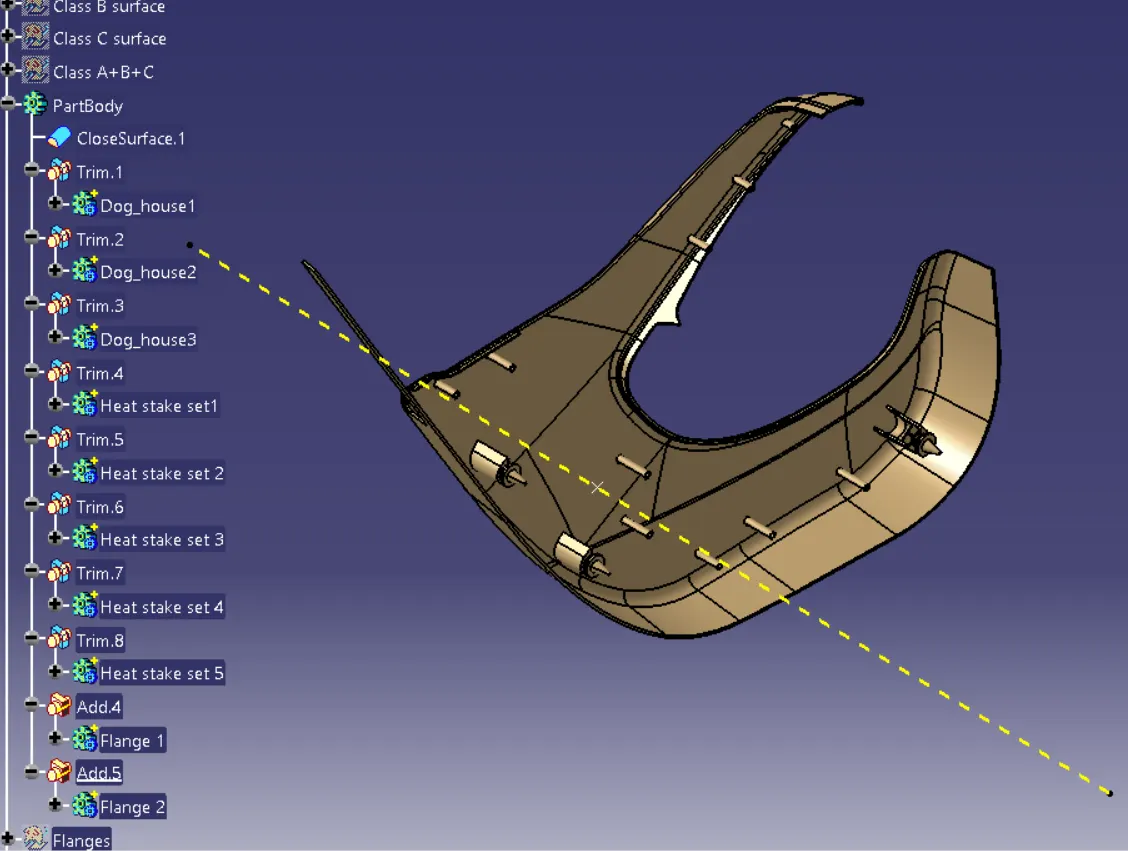
Close Body is created from the fully closed surface and then flanges & Heat stakes are created
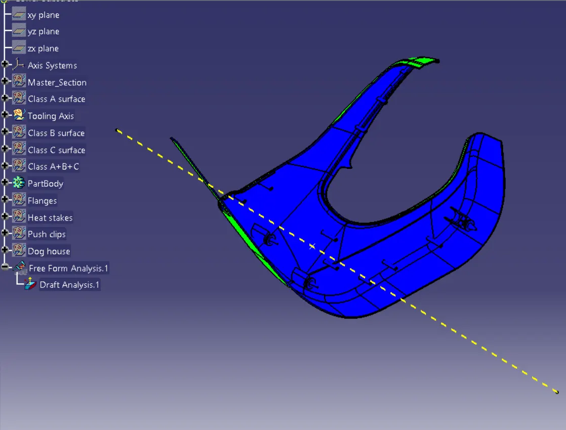
Drafting Analysis:
By applying drafting analysis at 3 Deg, we can see most bodies are been cleared. AsGreen is set at 3 degrees, blues is Zero, and less than Zero it is red colored.
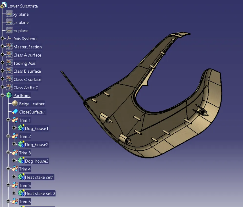
Applied material details such as Beige leather for the Lower Substrate.
3- Upper substrate:
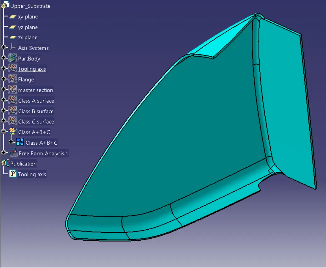
A- Class A Surface was checked and found out it is perfectly closed boundaries, no further action is to be taken.
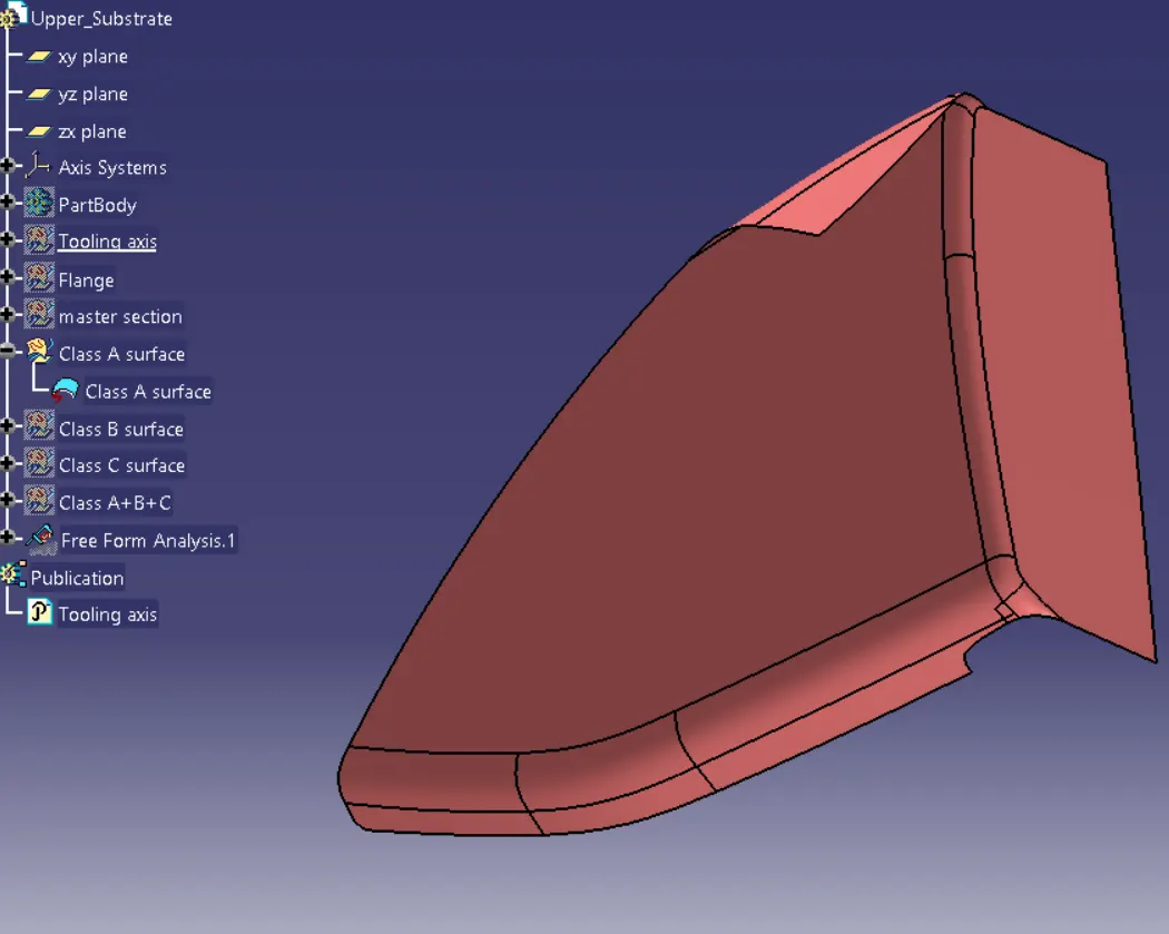
Class B is created by offsetting Improved Class A by 2.5 mm as per the master section
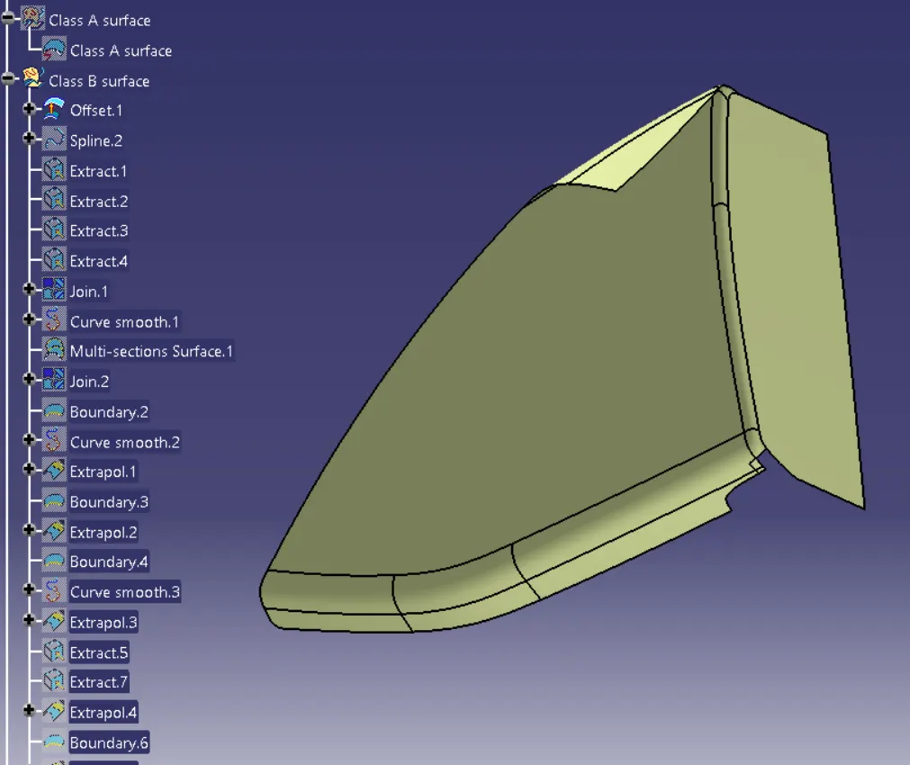
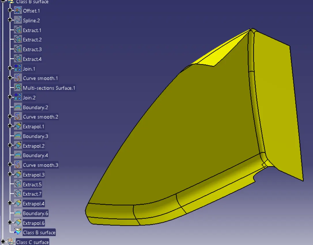
Class C is created by sweeping Improved Class A Surface and it has been trimmed with Class B Surface.
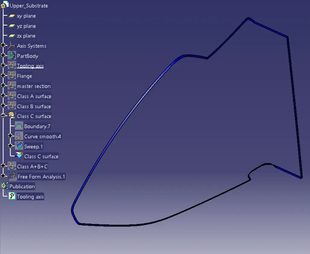
FINAL TRIM:
Join A and C surface.
Trim with the B surface.
TOOLING AXIS:
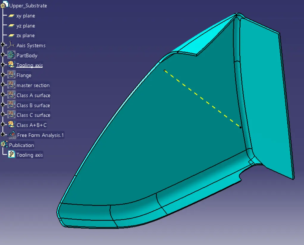
The tooling axis is defined as such all the features of the part can be manufactured easily. So here we followed the below steps to create the tooling axis.
- Tooling Axis created for the parts.
- Different ways of tooling axis creation are followed in OEM.
- Bisecting method, point, and direction are methods used here.
The Main Tooling Axis is created in such a way as to provide drafting.
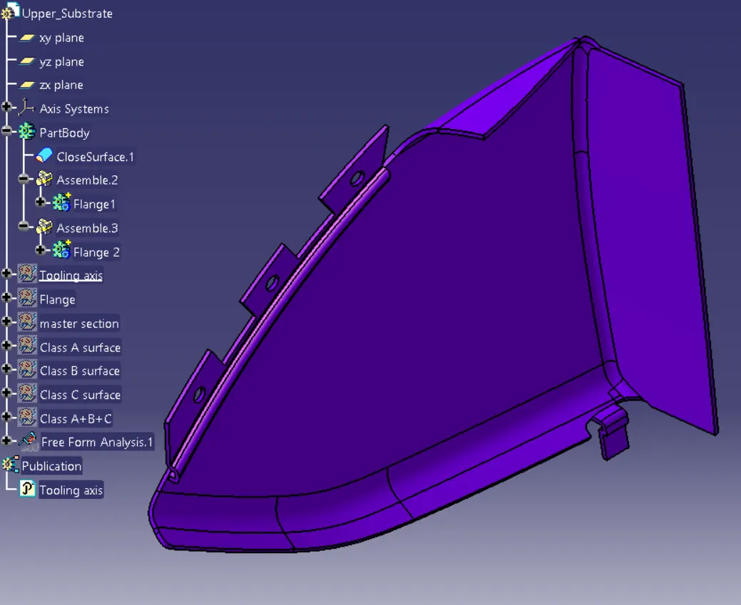
Close Body is created from the fully closed surface and then flanges & Heat stakes are created
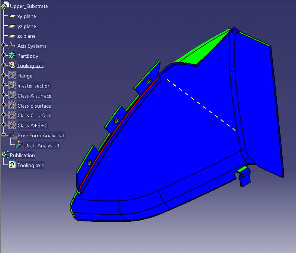
Drafting Analysis:
By applying drafting analysis at 3 Deg, we can see most bodies are been cleared. AsGreen is set at 3 degrees, blues is Zero, and less than Zero it is red colored.
Applied material details such as Black Dash board color for the Upper Substrate.
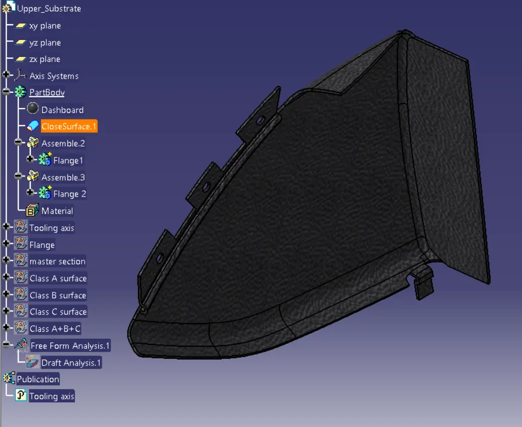
4- Bottle Holder:
A- Class A Surface was checked and found out it is perfectly closed boundaries, no further action is to be taken.
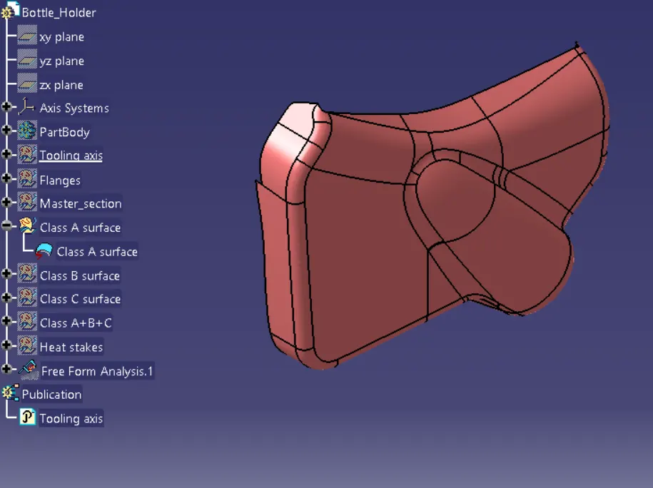
Class B is created by offsetting Improved Class A by 2.5 mm as per the master section
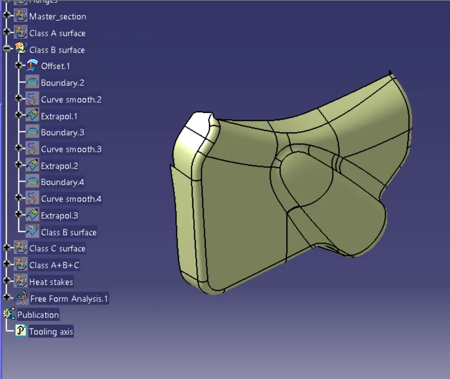
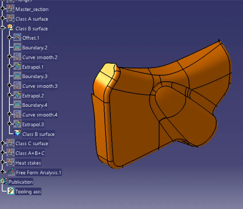
Class C is created by sweeping Improved Class A Surface and it has been trimmed with Class B Surface.
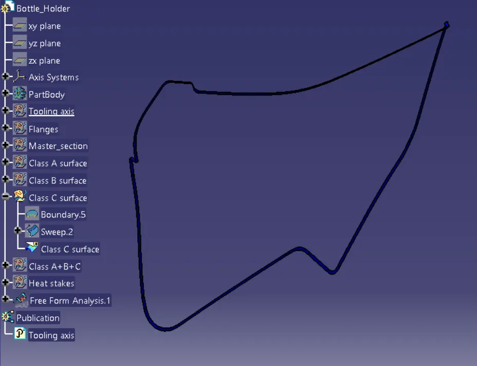
FINAL TRIM:
Join A and C surface.
Trim with the B surface.
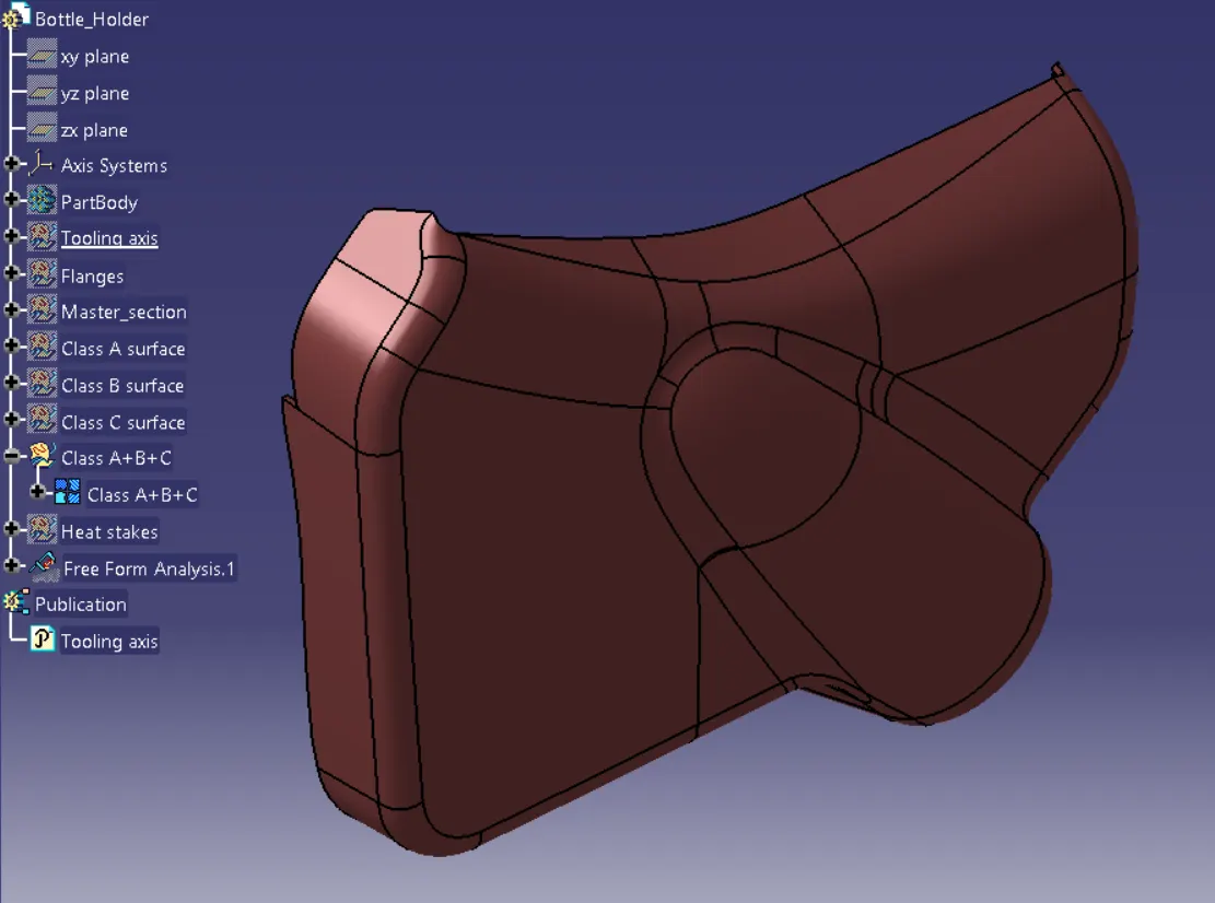
TOOLING AXIS:
The tooling axis is defined as such all the features of the part can be manufactured easily. So here we followed the below steps to create the tooling axis.
- Tooling Axis created for the parts.
- Different ways of tooling axis creation are followed in OEM.
- Bisecting method, point, and direction are methods used here.
The Main Tooling Axis is created in such a way as to provide drafting.
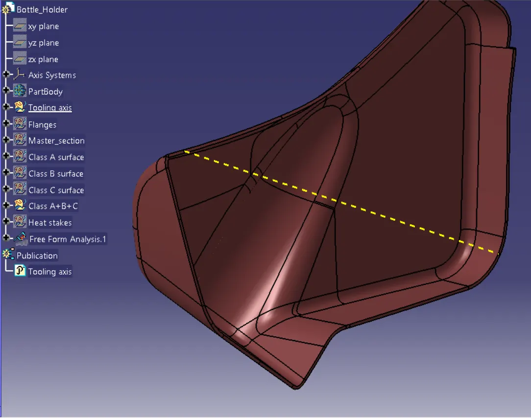
Close Body is created from the fully closed surface and then flanges & Heat stakes are created
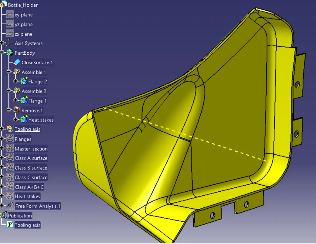
Drafting Analysis:
By applying drafting analysis at 3 Deg, we can see most bodies are been cleared. AsGreen is set at 3 degrees, blues is Zero, and less than Zero it is red colored.
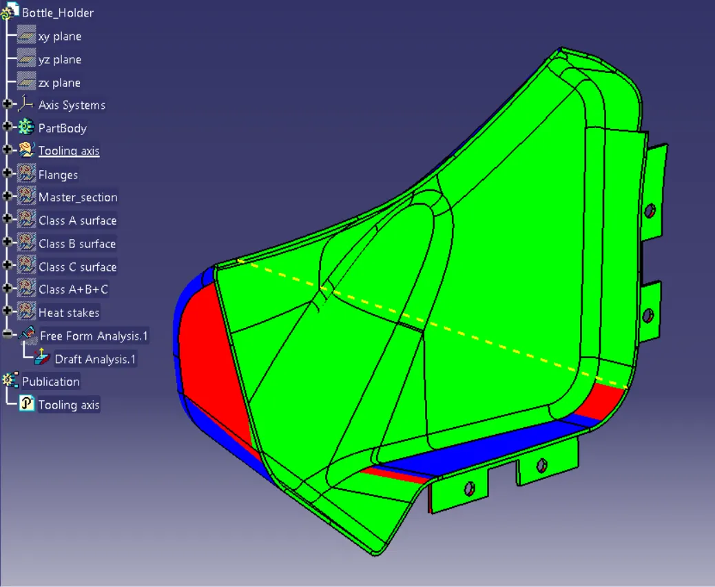
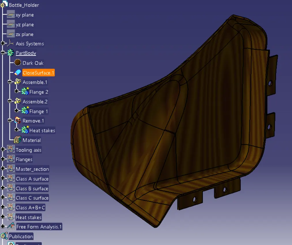
Applied material details such as a Dark oak color for the Bottle holder.
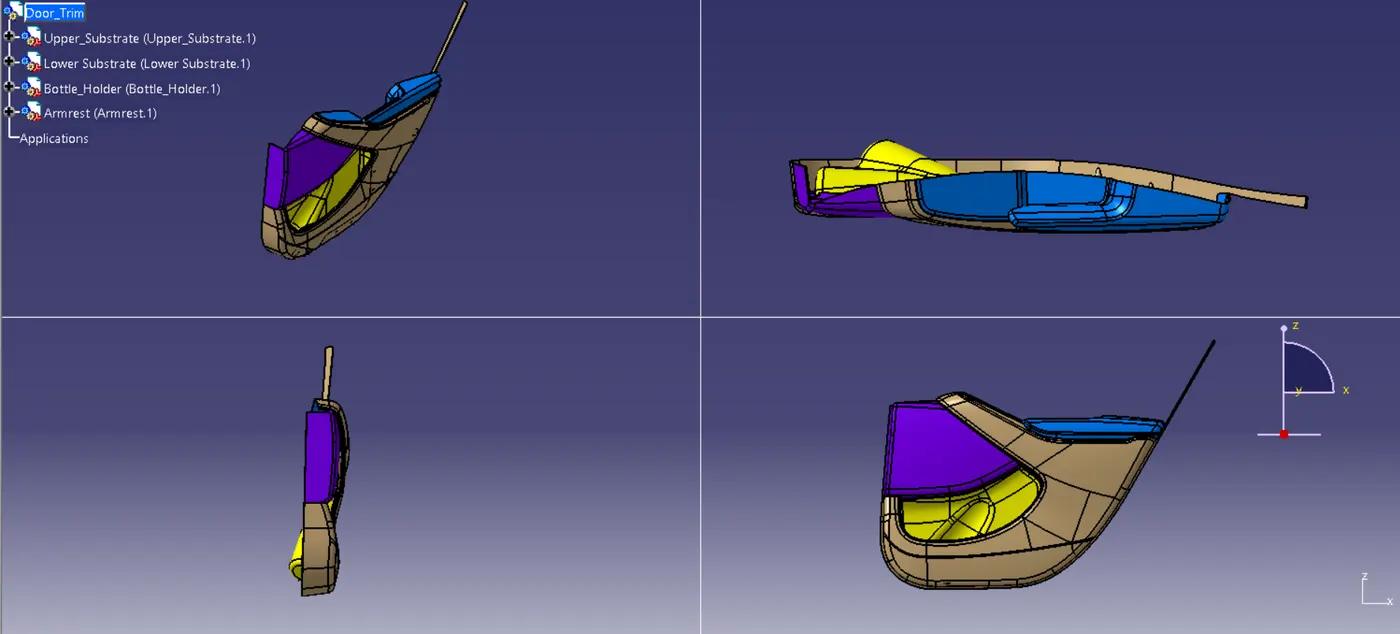
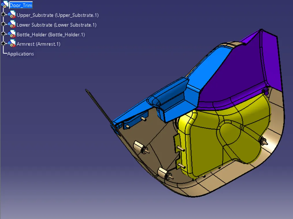
Photos of the door trim
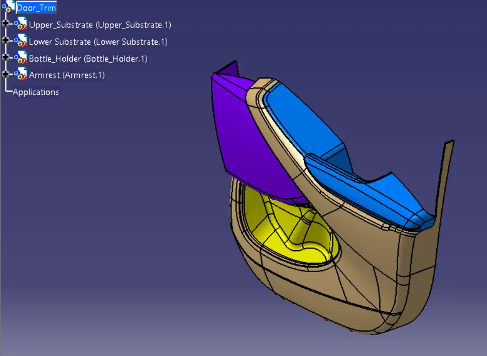
RESULT:
Thus we have developed the Door Trim panel