Week 9 - Challenge 1 - Base Bracket Design
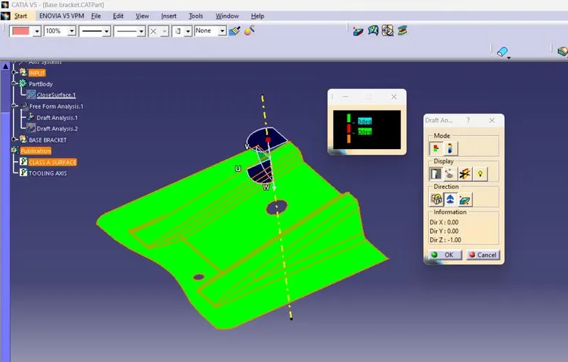
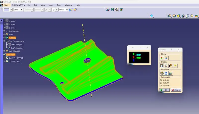
1. Screenshots of the Draft analysis report for both the given Class-A surface and the final plastic component
Draft analysis for given Class-A surface
Draft analysis for final plastic component
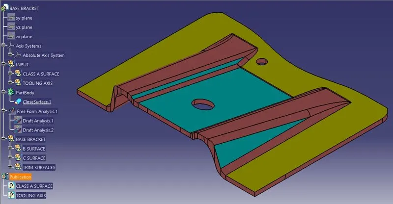
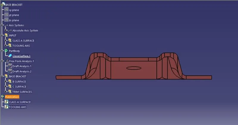
2. Screenshots of the solid model various orientations (Isometric, Front, Side, and Top View)
Isometric view
Front view
Top view
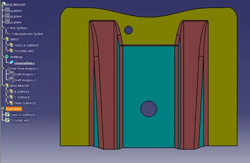
Side View
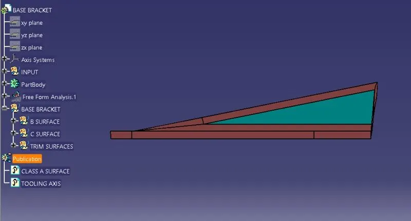
3. Detailed report for draft analysis and the tooling axis creation.
Tooling axis creation
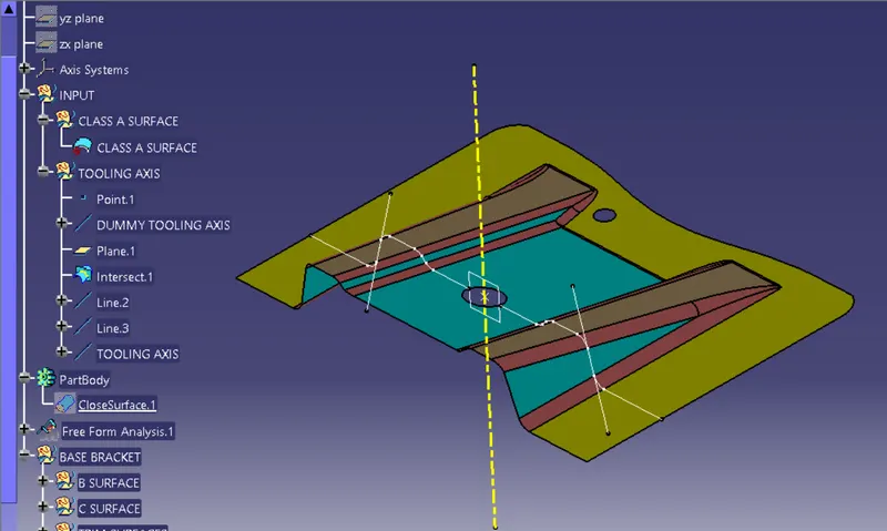
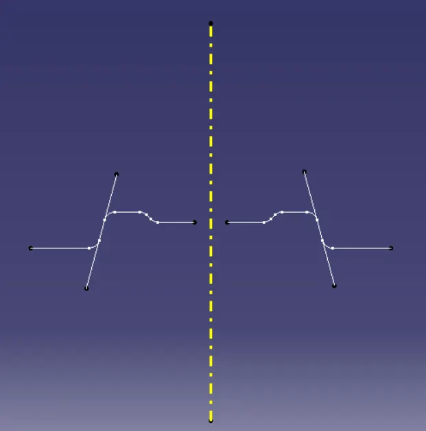
- First the connectivity between the surfaces to be checked, by using the join option
- Create a boundary for the hole. Using Circle / Sphere / Ellipse centre option create a point in the boundary. Create a line using point – direction of “Z” direction option and name that line as dummy tooling axis.
- Insert an axis system ensure that is not in current.
- By using the point – point line option extend the line along the sketch. With the bisecting line option selecting the two line the tooling clearing “X” direction is created.
Draft analysis
- First the compass is moved to the part. The compass sholud be placed on the tooling axis. which used to define the new current draft direction, then lock the draft direction using the lock icon
- The colour chart indicates the various condition of the draft angle . the green colour indicates that the part passes and the and can be used for the further operations
- By using the analysis under the running point icon we can check draft angle at the various surfaces of the component.
CONCLUSION
Thus the DRAFT ANALYSIS is carried out by tooling axis for the given class - A surface Base Bracket.