Week 10 - Challenge 1- Attachment Feature Creation (Ribs & Screw Boss)
Attachment Feature Creation (Ribs & Screw Boss)
Design of the door handle with engineering features:
AIM: To create the door handle component by generating the class B and class c surfaces with the aid of class A provided and creating the B side features including the ribs and the screw bosses by following the design parameters.
Procedure followed:
The following steps are included while designing the door handle with B-side features
- Tooling axis creation
- Draft analysis of class A surface
- Class B surface generation
- Class C surface generation
- Final trim
- Solid-body generation
- Draft analysis of the solid body
- Ribs creation
- Screw boss creation
- Draft analysis of the solid body with B-side features
Tools used:
- Boundary
- Join
- Multiple extract
- Bisecting line
- Trim
- Surface offset
- Draft analysis
- Intersect
- Surface sweep
- Close body surface
Description:
1. Creating tooling axis -
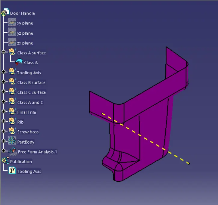
- It is defined as the direction in which the mould/core and cavity open. The selection of the direction of the tooling axis depends on the ease at which components can be easily ejected.
- Open the given CAT/STEP class A surface file. Ensure that the given surface is a closed surface. This can be fixed by using the join option. For verification use the join tool or the boundary tool.
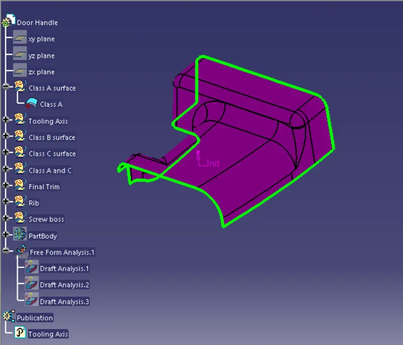
- An axis for the tooling direction is decided through visual inspection. The tooling direction in this model will be created parallel to the Y direction. For this, a point is inserted in the extracted base surface of the component. An axis system is inserted along this direction.
2. Draft analysis of class A surface
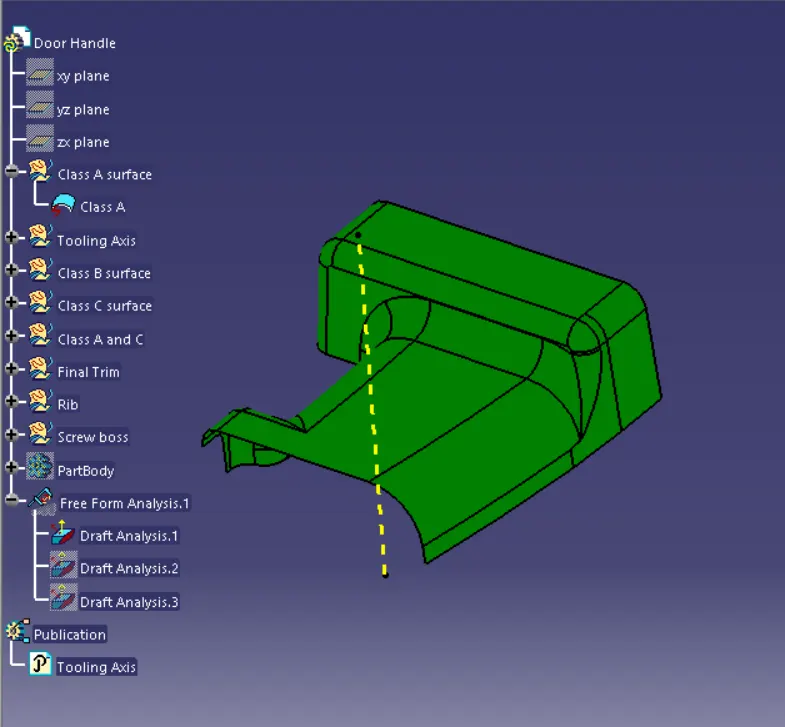
- The surface to the analyzed is selected and the mterial options is turned on in the customize option.
- The feature draft analysis tool is opened.
- The compass is aligned with the tooling direction.
- It is made sure that the pulling direction is correct. Otherwise, it is flipped from the open toolbar.
- The surface is selected to make sure that the draft values are within permissible limits on all faces.
3. Class B surface generation
- Class B surface always lies beneath the class A surface with an offset value of less than or equal to 3mm.To offset the class A to an offset value of 2.5mm
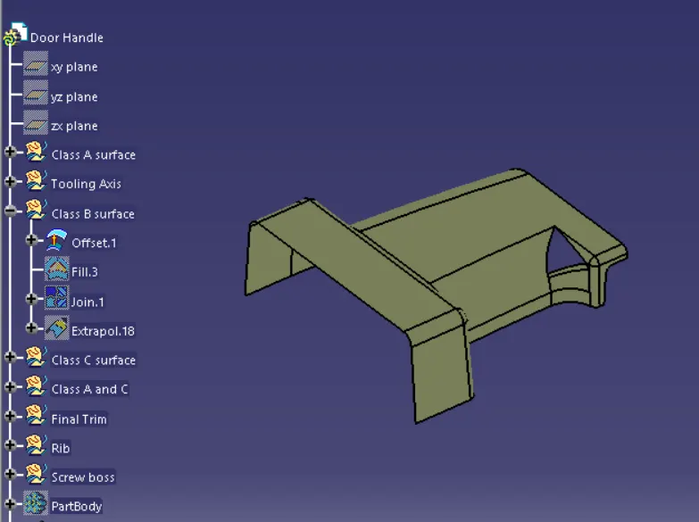
- So after offsetting the class a surface e there may be a generation of a patch so we need to work on it to complete the generation of entire B surface
- So we use the multisection surface feature to close the patch.
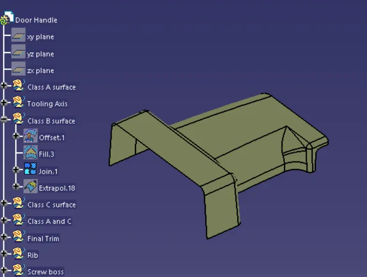
- Now join the two surfaces using the join command to form the entire B surface.
4. Class C surface generation
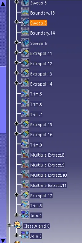
With the aid of the class A surface create the class c surface by using the sweep feature. If the generated C surface is parallel to the tooling Axis create the sweep along the draft direction with a draft of 3 degrees or if the surface is perpendicular to the tooling axis then create the sweep using the reference surface option then extrapolate the connecting surfaces and trim the surface together and join them all together to form the class c surface
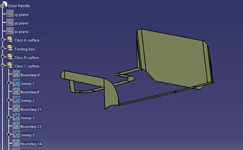
Now join class A with the Class C surface
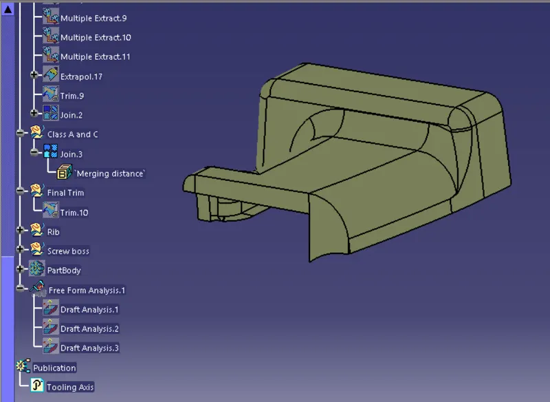
5. Final trim
Now trim and join the class B surface with A & C
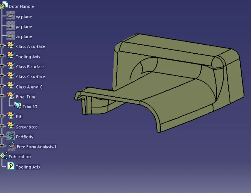
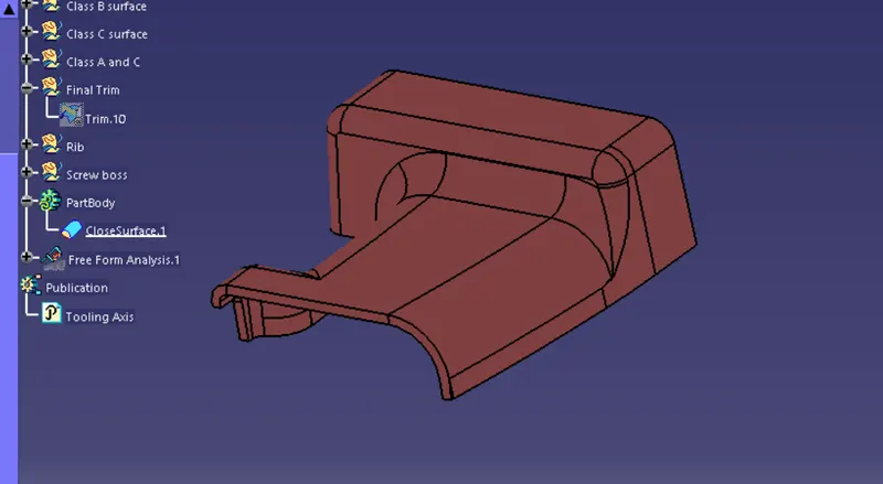
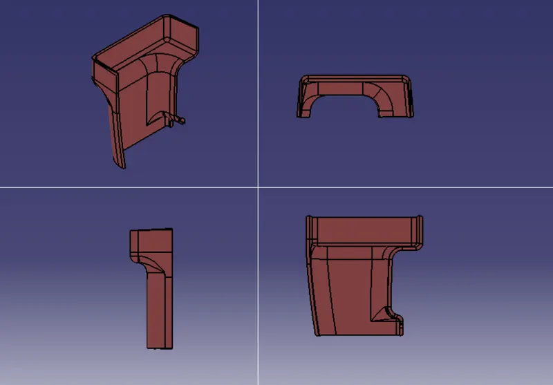
6. Solid-body generation
Go to the part workbench and apply the solid surface feature to the final trim surface
7. Draft analysis of the solid body
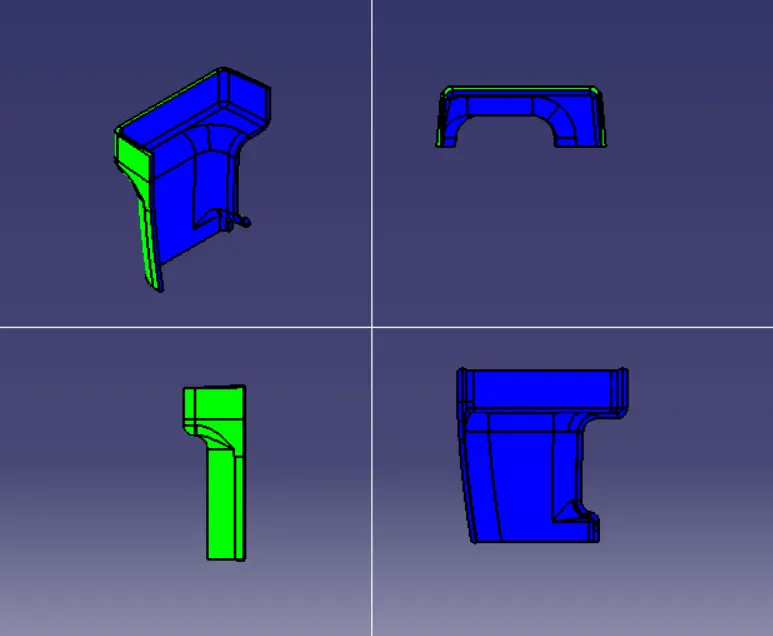
Draft analysis is a method used in design to check whether the component created in CAD is manufacturable based on the draft condition applied. The main reason behind the draft analysis is the part manufactured should be easily removed from the mold. It also gives an idea of the draft angle from the tooling direction. Here we are giving a tooling direction in order to eject the component easily from the tool. The ideal draft angle given in automotive industries for plastic components is 3 degrees.

8. Ribs creation
RIBS CREATION:
Ribs provide a mean of strength and stiffness to the molded component without increasing the overall wall thickness
Ribs basically facilitate:
- Locating and arresting the components of an assembly
- Providing alignment in mating parts
- Acts as a guide or stops mechanisms
Design parameters:
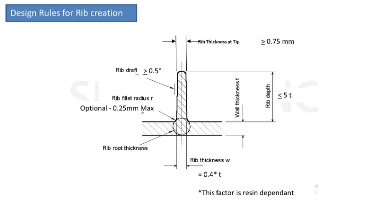
- Draft: 0.5 Degrees per side (minimum) and maximum upto 1.5 degrees
- Thickness of ribs: 40 to 50% of wall thickness
- Height: ≤ 5 times the wall thickness
- Spacing (for more than 1 rib): 3:1- steel height/width ratio (maximum). h/w =3 or2(preferred) where h is the height of the rib and w is the space between two ribs.
- Minimum thickness at the tip: 0.75mm
- Rib fillet Radius: 0.25mm max or 0.125*thickness of the component
- Rib root thickness should not be more than 30% of the wall thickness.
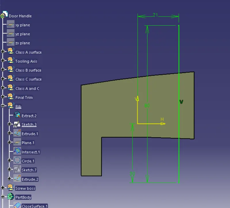
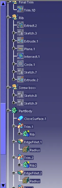
Extract the surface and create a plane and select the plane for the sketch and draw an iso-constrained line and extrude the line to a height of H = 5*2.5=12.5mm
Now thicken the extruded surface to 1mm as w= 0.4*2.5=1 mm
Now apply the draft to the surface as a reference to the extract and use the pulling direction as the tooling axis to a draft of 0.5 degrees on each side.
Now union trim the rib with the main solid body of the door handle
Now apply the fillets of 0.25mm on each side
Find the rib root thickness by taking the intersection of the rib and creating a tri-tangent circle and finding the diameter of the circle which must not be 30% more than the wall thickness
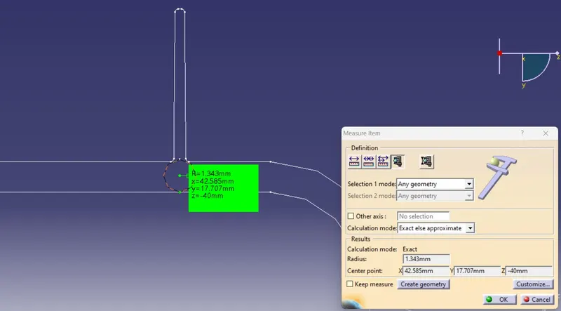
so the rib root thickness is 2.686mm so 30%* wall thickness =0.3*2.5=3.25 mm
So rib root thickness is satisfied as 2.686 mm < 3.25 mm
Now apply the same design parameters for creating the rib 02
After all, apply the draft analysis and the ribs can clear the draft at 0.48 degrees
9. Screw boss creation:
Screw bosses generally find use in many part designs as points for attachments and assembly. The most common variety consists of cylindrical projections with holes designed to receive screws, threaded inserts or another type of fastening hardware
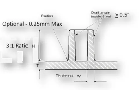
Design parameters:
- The outside diameter should be 2 to 2.4 times the inside diameter
- W= 0.6*T
- Draft 0.5 Degrees on both the inside and outside walls of the screw boss.
- Height-to-diameter ratio – 3:1
- Radii(fillet) – 0.25mm(maximum)
- Boss Gussets must meet rib guidelines
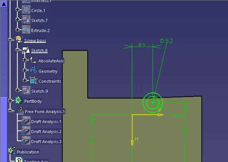
So pad the sketch to a height of H= 5*2.5= 12.5mm so better to extend the pad to the other side a little bit of 20to 3mm so that the proper assembling will be possible with the main body part
Now apply the draft of 0.5 degrees on the inside and outside diameter faces
Now create the ribs for supporting the ribs by following the rib design parameters
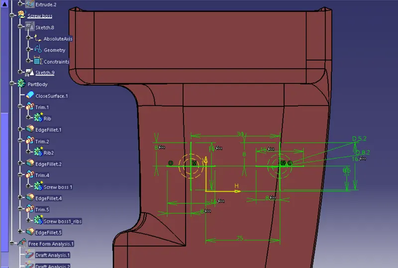
So the height of the rib would be 60% of the height of the screw boss
apply the draft of 0.5 degrees to all over the sides of the ribs
Use the boolean operation of union trim to assemble the ribs and the screw bosses to the main solid body
Now generate the other screw boss at a certain distance
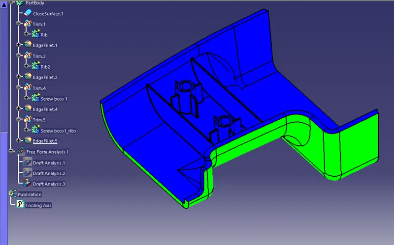
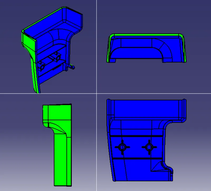
10. Draft analysis of the solid body with B-side features
Now generate the other screw boss at a certain distance. Perform the draft analysis of nearly 0.5degress to check whether all the B side features are clearing the draft analysis or not
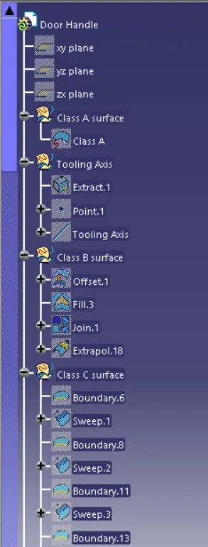
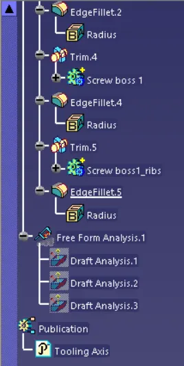
Tree structure:
CONCLUSION:
I have created the tooling axis using the given CLASS-A surface and created B side Features on the door handle solid body. Also performed draft analysis on both Class-A surface and Final part body with B side features.