Week 12- Final project
Aim:
To create cad model of complete door panel along with its fixation to be fixed in BIW with help of class A surface & master section as used in OEM.
Main Objective:
To define tooling axis & check draft analysis to find tooling feasibility of style surface.
To create Class B surface & class C from class A surface.
To form solid body by combining the Class A,B & C surface.
To Decide the fixation of part a master section provided.
To check draft analysis solid body & fixation provided.
Input Provided:
Class A surface is very important which is aesthetic outer skin can be feel by the passenger.
This is not an easy shape rather a complex one through-out the area of a car. According to application & place where it is used material may varies.
Procedure to follow to complete Project:
1. To check the quality of A surface for modification.
2. As the input is provide in single part file need to segregate into four separate part file such as Door Armrest, Lower substrate, Bottle holder, Map pocket.
3. To create tooling direction for each part.
4. Perform draft analysis for each Class A surface.
5. Create class B & class C surface.
6. Combine Class A, Class B, Class C surface for all parts.
7. Create attachment feature for all part
8. Finally do draft analysis along with feature
& constrain them.
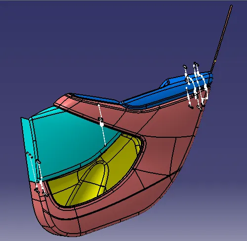
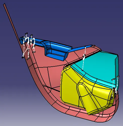
Door Armrest:
1. Check the given Class A surface for improvement. As a result given class A surface is not need to be improved
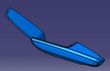
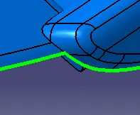
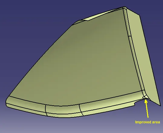
2. Improved Class A surface in this corner area a gap available solved.
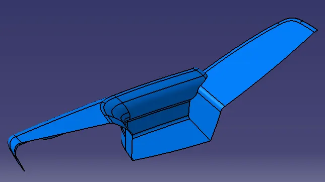
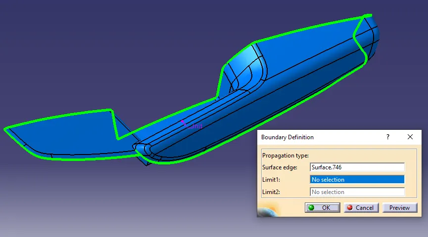
Before Improvement:
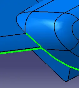
After Improvement:
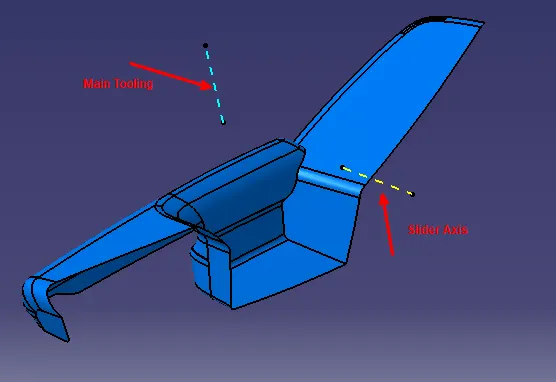
Create Tooling direction:
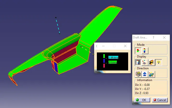
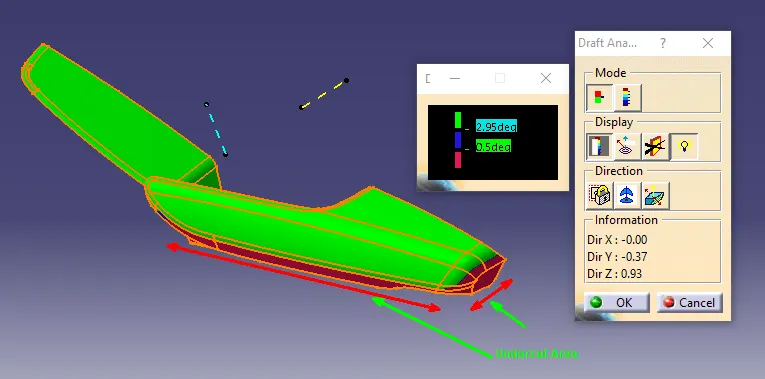
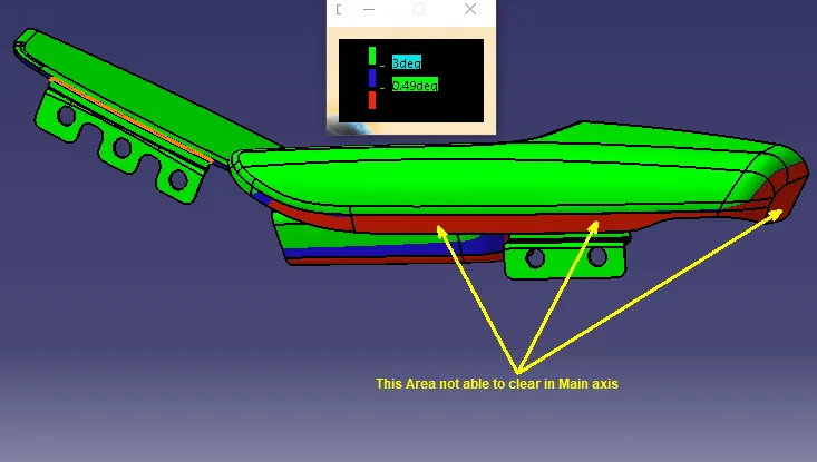
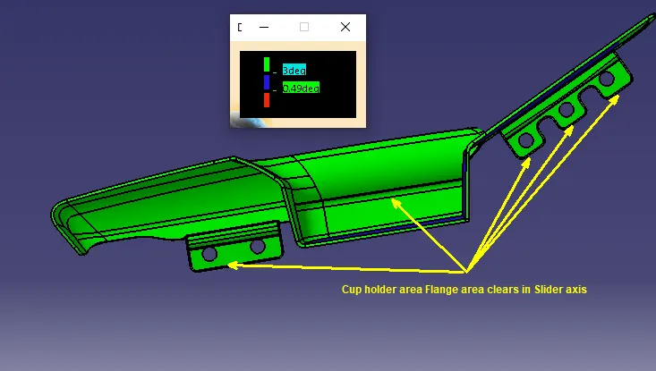
Initially need to define the main tooling direction check draft some area not clearing in current remolding direction So consider Slider to clear that area.
Draft Checking Class A surface:
While checking draft some area some area we can clear with main tooling & in some undercut area we can clear with slider & other area request customer or styling team for modification.
Creation of Class B surface:
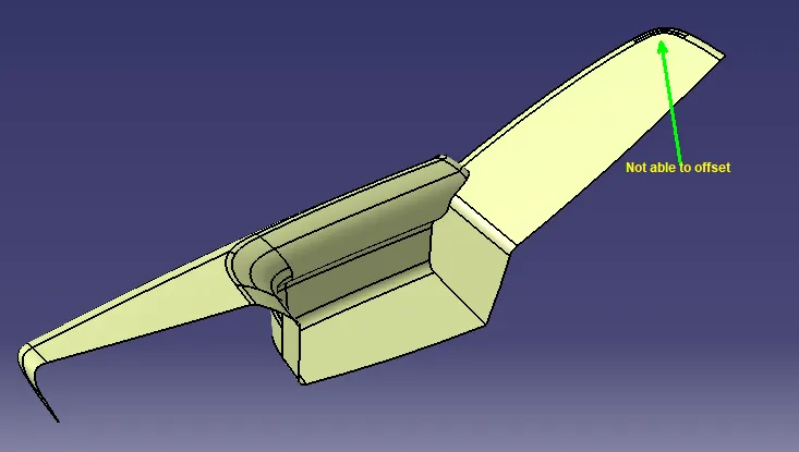
As per master section part thickness is 2.5mm, while offset the surface most of surface offset & some below mentioned surface not able to offset due to surface quality in that area we can work location by multi section options.
Creation of Class C surface:
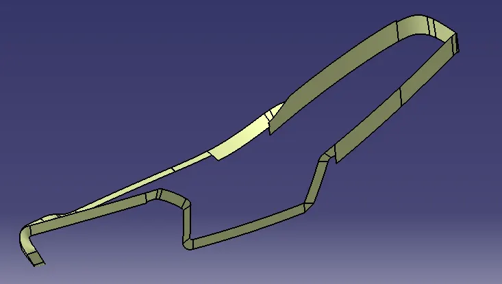
Class C surface is side wall for making thickness area as we know extract the boundary of class A & sweep in tooling with angle of 3 degree. In some bending area sweep not happening so we can used multi section option to form a wall throughout.
Creation of Closed body:
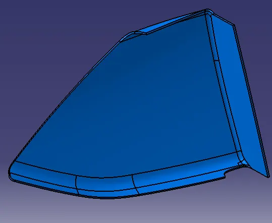
As we created class B & Class C surface & Class A surface we can combine this with join option to make closed body.
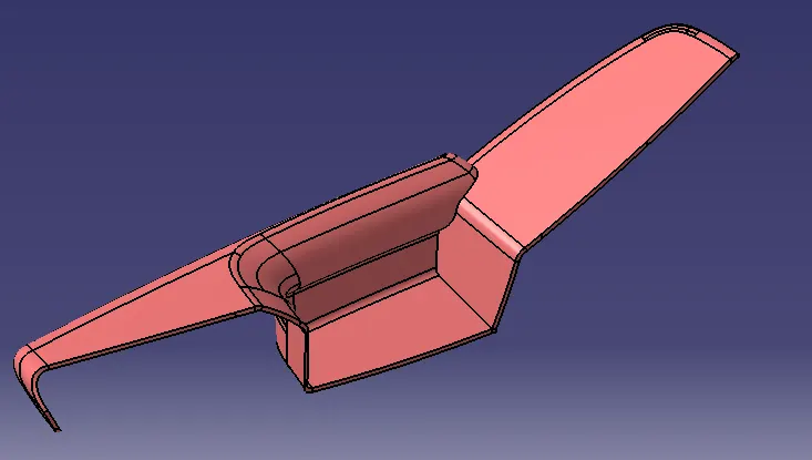
Creating Flange on Armrest:
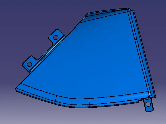
From master section we know that Creating flange on armrest for fixing in Lower substrate position for heat straking.
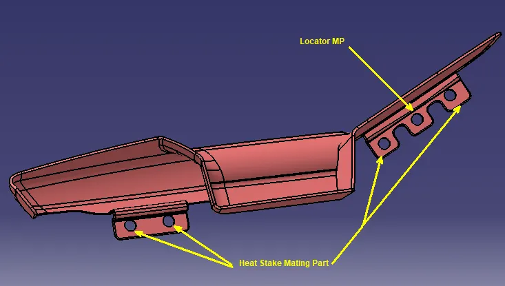
Why Draft required?
Every part has to be released from mold after completing filling process in the process in mold. If no draft is provided to the part, it will stick in mold not able to eject from mold. So considering tooling draft will provided for parts. Each part has specific draft by considering we can provide draft of 0.5deg to 3deg.
From above point we can come to conclusion that after considering main demolding direction & sider direction part needs more modification to be manufactable by modifying class A surface.
Map Pocket:
Checking of class a surface if any improvement needed.
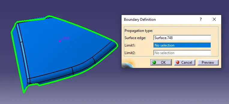
Creation of tooling Direction:
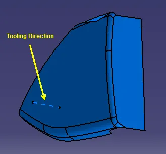
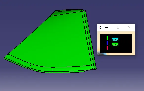
Draft analysis:
While checking draft we can know that part has draft more than 3 degree.
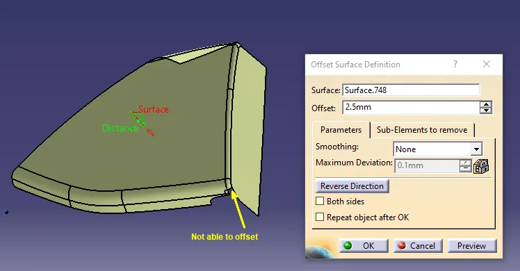
Creation of class B surface:
Class B surface can be created by offset Class A surface. From master section we can come to conclusion that 2.5mm thickness for the part. Below mentioned area not offset so we can create a patch surface.
Creating Class C Surface:
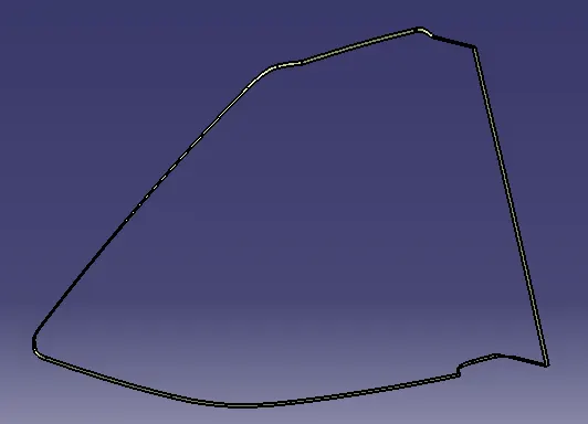
C surface with connect the class A style surface & class B engineering surface. By considering draft of 3degree make sweep by extracting boundary from class A surface to get Class C surface.
Final Solid Body:
Creation of flanges:
From given master section we can get an idea for flange creation which assemble in counterpart of Lower Substrate
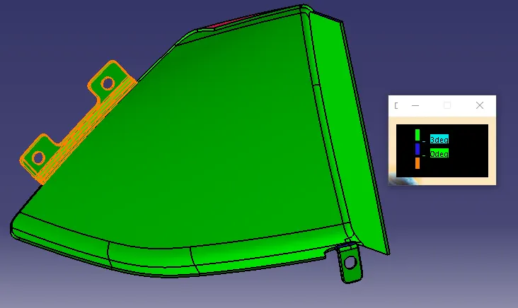
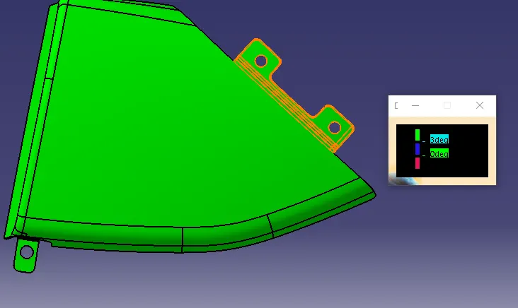
Draft analysis of Final part with fixation:
From below draft analysis, we know that part has a minimum draft 3 degree is all since part is manufacturable.
Bottle Holder:
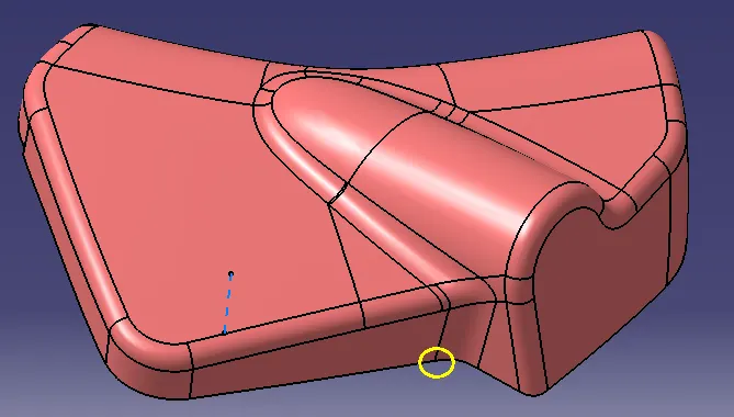
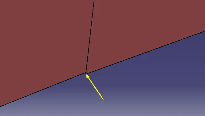
Check the quality of class A surface.
Improve the Class A surface by multisection operation.
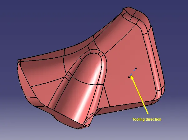
Creating Tooling axis:
Draft Analysis on Class A:
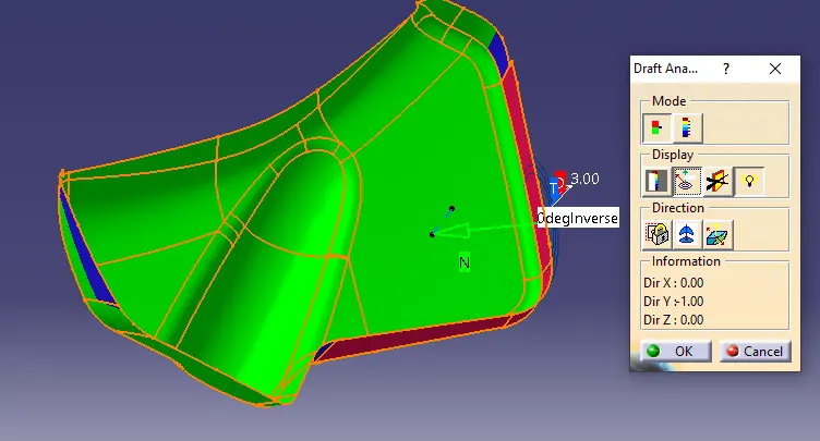
From draft analysis we come to know that some area has minimum draft & 0 draft in some area needs improvement.
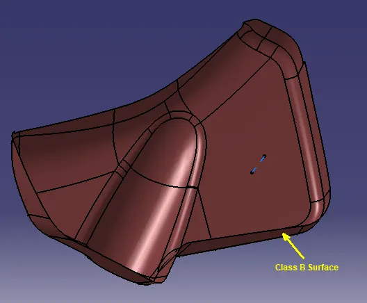
Creating Class B:
For creating Class B surface we have to offset the class A surface 2.5mm.
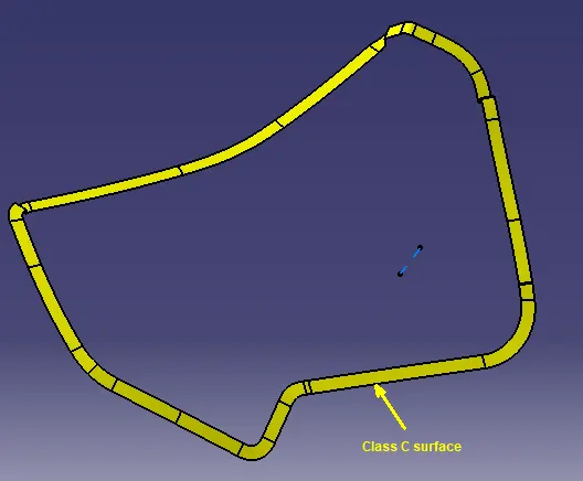
Creating Class C:
For Creating Class C surface need to sweep the outer boundary in tooling direction.
Bottle Holder solid body:
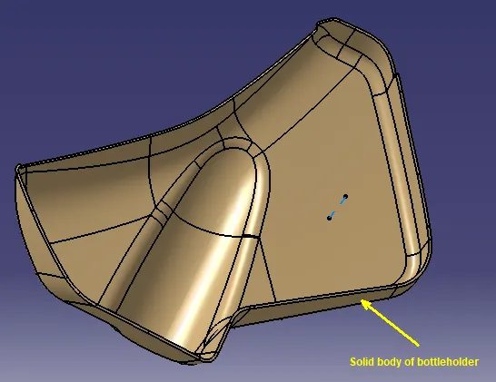
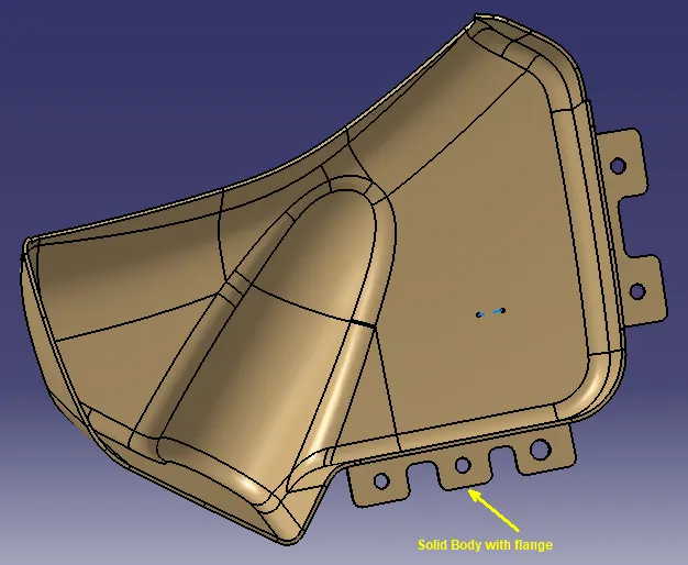
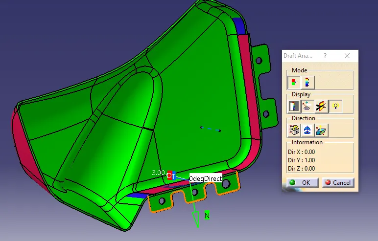
Draft analysis:
After creating the solid and fixation we confirm that some area has less draft so part is not feasible for manufacturing. We can inform to style team to improve style.
LOWER SUBSTRATE:
Class A surface
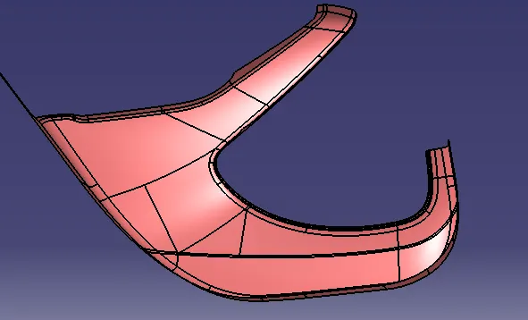
Creating Tooling axis:
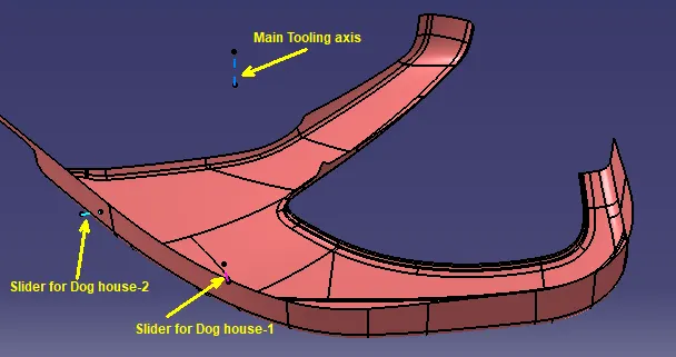
Draft Analysis on Class A:
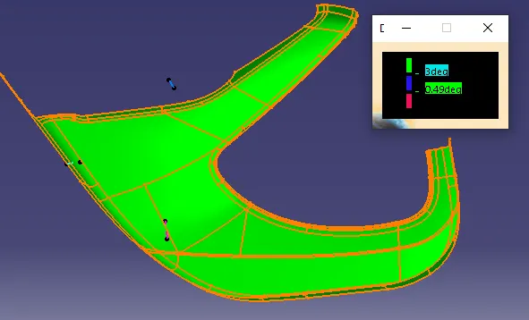
From above image we can know that Class A clear with required draft angle 3 degree.
Class B Surface & Class C Surface:
class B & Class C surface creation using thickness option.
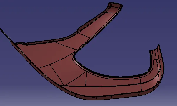
Checking draft for solid Body:
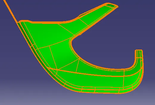
As seen above that class A surface clears the draft & also solid body also clears the draft.
Fixation creation :
Heat Stake :
Heat staking is a joining process of two different part with the help of heat usually used in thermoplastic material.
Material used for heat staking: PP, PC,ABS.
Points to consider while designing a heat staking is to maintain height less that than height of locator.
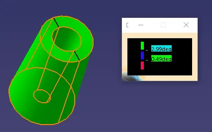
Draft for Heat staking:
Locator:
The main purpose of locator is locate & keep part in position while assembling parts.
There different type of locator such as four way locator, two way locator & cylindrical locator.
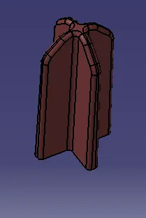
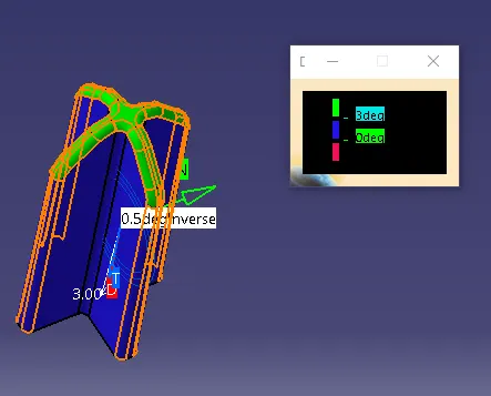
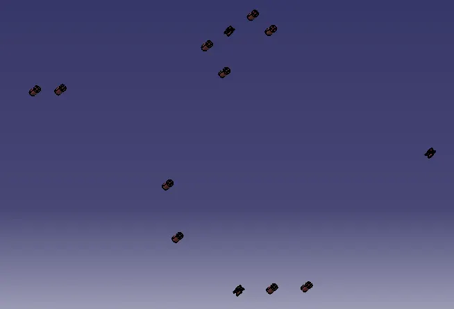
For above we can see the position of heat staking, Locator & dog house. These feature area created
by considering the counterpart.
Dog House:
Dog house is create to avoid sink mark on the surface & solve the length problem with engineering feature at the required height.
Wall thickness at the join area is 40% of main wall thickness & height should be 3.0~6.0mm.
Minimum draft angle should be 0.5 deg.
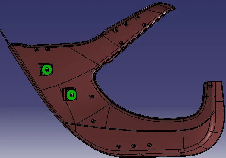
Assembly Output:
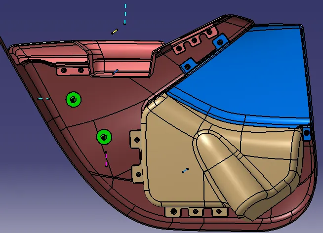
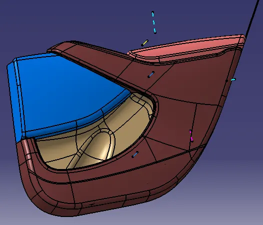
Conclusion:
I learned how to develop CAD models for plastic parts by taking design rules into consideration from this assignment. I became really familiar with part workbench, surface workbench, and assembly workbench by working on this project on Catia V5. I also gain confidence in my ability to operate the various workbenches' functions. In addition, this gives me ideas for designing parts that take manufacturing and assembly into account.