Week 12- Final project
WEEK 12 - FINAL PROJECT
DEVELOPMENT OF A DOOR TRIM PANEL
AIM:
To develop door trim panel.
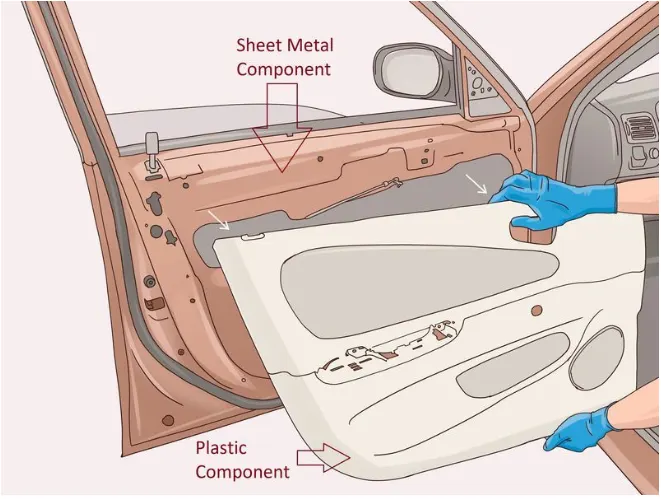
OBJECTIVE
- Class A surface
- Nominal thickness (from master sections)
Attachment strategy:
- Push pins with dog houses for lower substrate to door panel attachment
- Heat stakes for part to part attachment
The outputs of the design were:
- Thickened part using master section for reference
- Mounting features as per design guidelines in the industry and with master sections
- Material details
- Draft analysis & tooling analysis
- Creation of parting lines and check tooling feasibility
SOFTWARE USED:
CATIA V5
INPUT
CAD DATA is downloaded and opened with catia
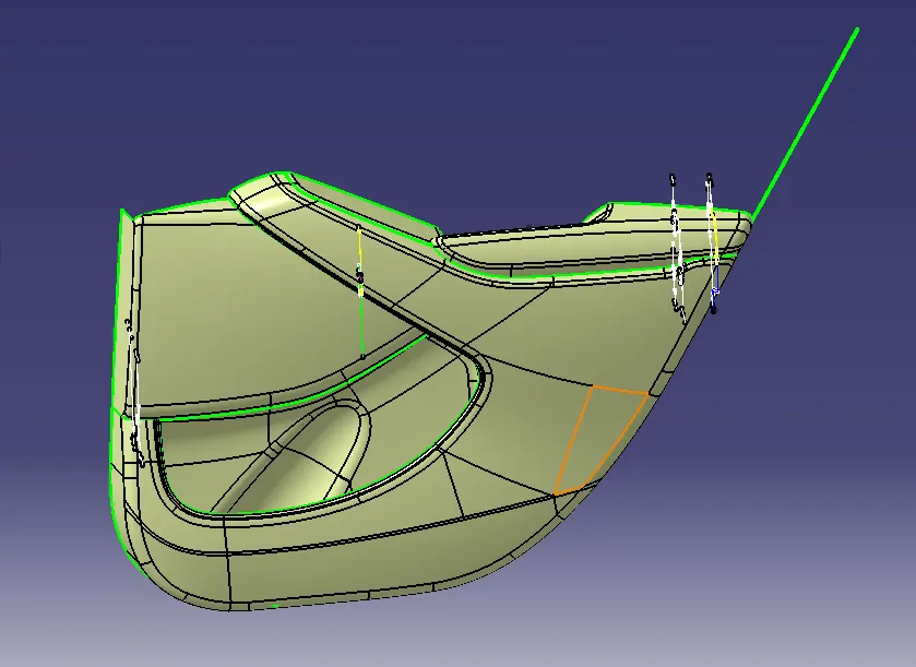
CREATION OF TOOLING AXIS
The tooling axis is established to facilitate the smooth manufacturing of all features in the part. In this process, various methods are employed, with the OEM (Original Equipment Manufacturer) utilizing different techniques for tooling axis creation. The bisecting method, point, and direction methods are applied in this context. Additionally, when necessary, a side core axis is defined.
The following are photos depicting the created tooling axis.
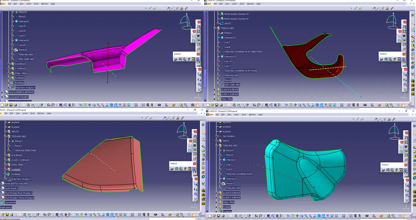
DRAFT ANALYSIS
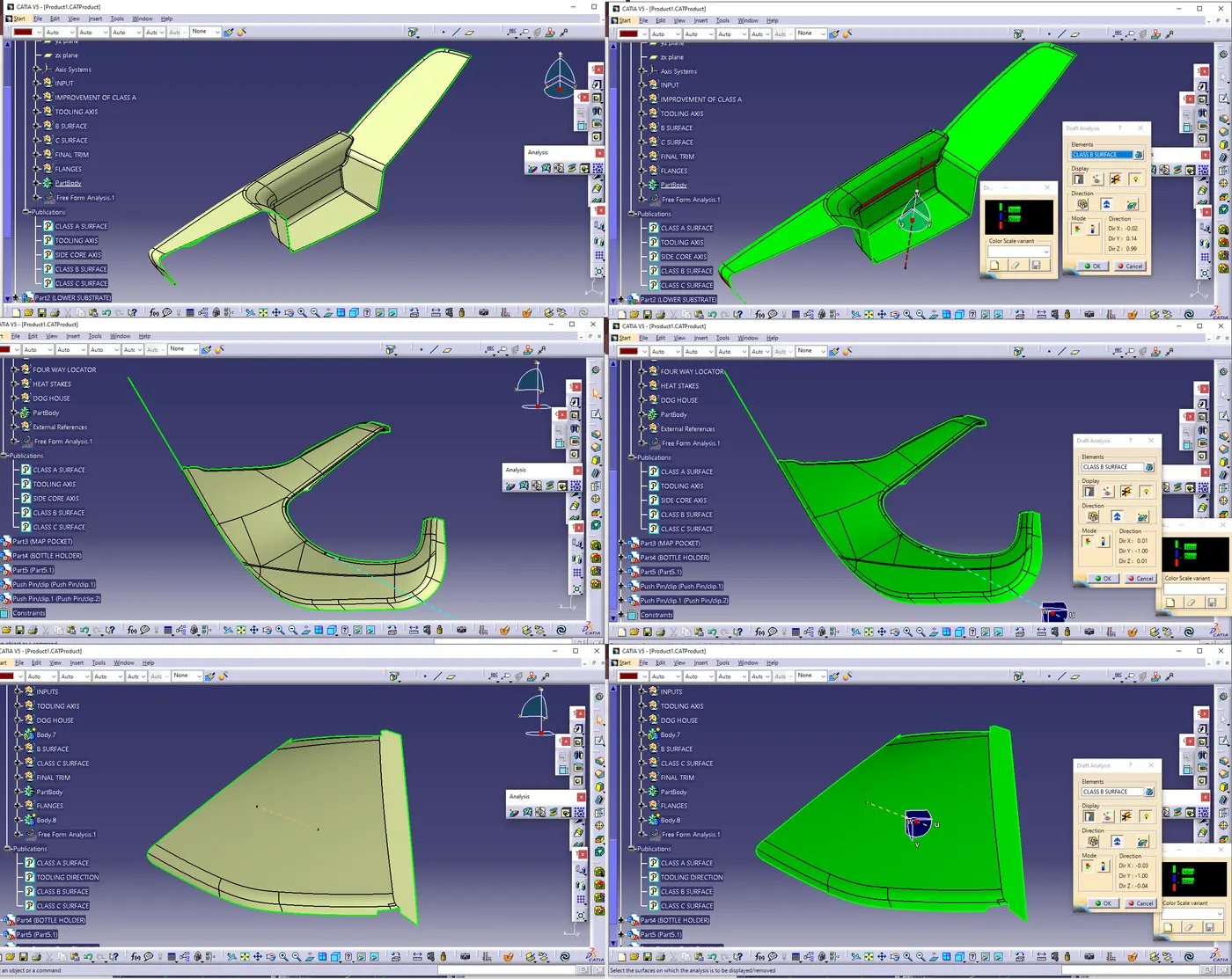
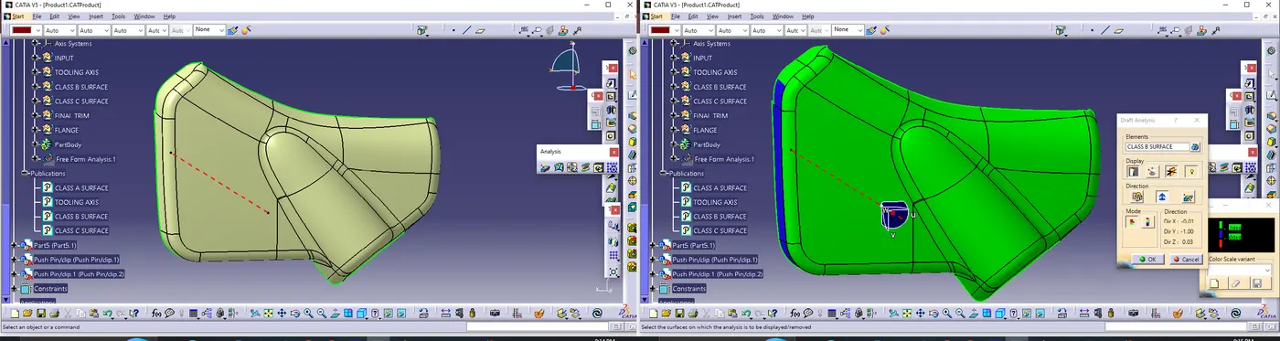
- The draft has been applied to the Class A surface of the parts. Switch to the material in material mode.
- Click on the Draft analysis tool, and select the surface. Align the compass to the tooling axis.
The clearing angle is set to 3 degrees. In the customized view, inspect the draft analysis results. The cleared sections are highlighted in green. However, some areas are defective and did not meet the 3-degree clearance. Please take those sections into consideration.
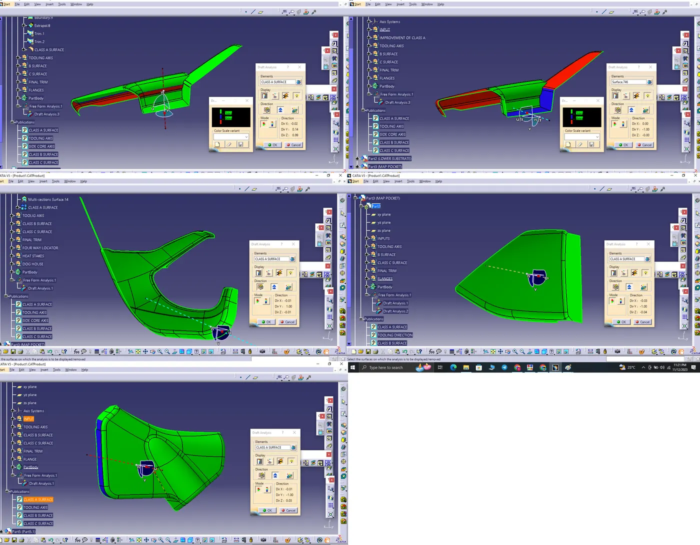
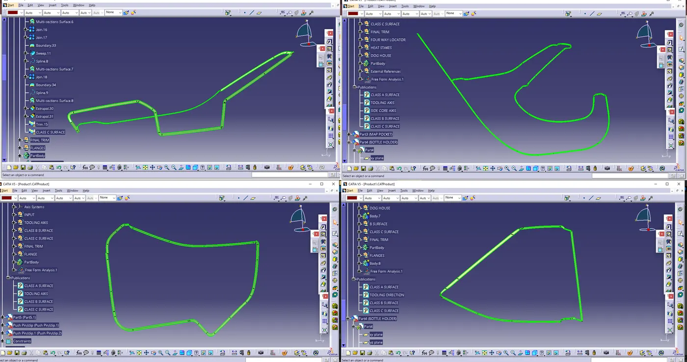
MASTER SECTION IN THE CLASS A SURFACE
CLASS B SURFACE
Creating the B-surface for the door trim panel involves using master sections as a guide.
CLASS C SURFACE
CREATION OF B SIDE ATTACHMENT FEATURES
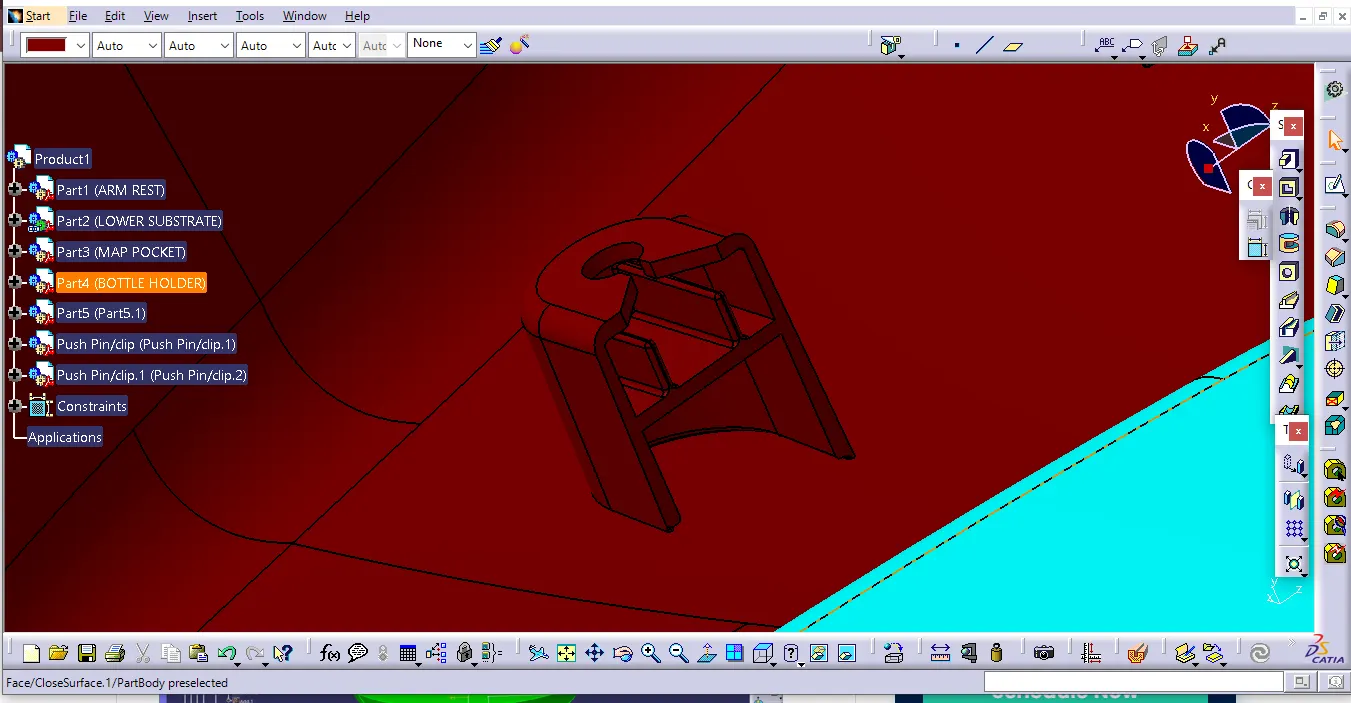
DOG HOUSE
- Extract the surface that we going to create a dog house Insert a axis system.
- use positioned and draw a dog house sketch Sweep the sketch to 1.5 degree on the direction of main tooling axis.
- To apply a thickness of 2.5mm to the sketch while adhering to the Dog House Rule (B=4mm, t=2.5mm, C = 0.4 * t = 1 mm),
follow these steps:
1.Thicken Surface:
- Utilize the Thicken Surface feature to add a thickness of 2.5mm to the sketch.
2.Dog House Rule Application:
- Adhere to the Dog House Rule:
B = 4 mm
t = 2.5 mm
C = 0.4 * t = 1 mm
3.Sweep and Offset:
- Extract the sweep and offset it to B = 4 mm and C = 1 mm In all directions.
4.Trimming
- Trim the portion to obtain the desired sketch.
5.Draft Analysis:
- Apply a 5-degree draft along the second tooling axis.
6.Fillet:
- Add fillets to all faces of the sketch.
7. Assembly:
- Assemble the doghouse to the lower substrate solid.
8. Translation:
- Translate the doghouse to the desired location.
9. Pushpin Placement:
- To place a pushpin on the doghouse, create ribs extending to the doghouse.
10.Trimming Ribs:
- Trim the ribs using the doghouse to achieve the desired configuration.
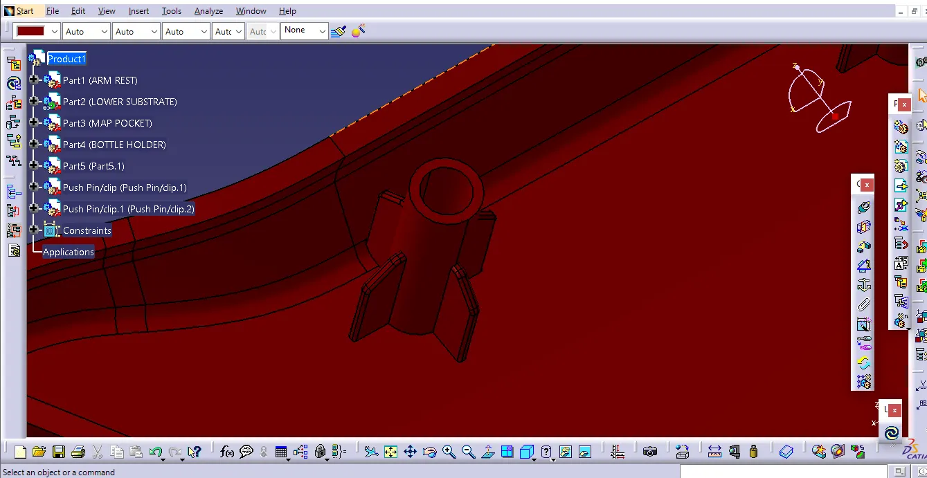
HEAT STAKES
1. Surface Extraction:
- Extract the surface where the heat stake will be created.
2. Positioned Sketch:
- Use a positioned sketch and draw the required heat stakes sketch.
3.Pad Command:
- Utilize the Pad command for the sketch until the desired height is achieved.
4. Drafting:
- Apply a draft to the heat stakes, ensuring a minimum of 0.5 degrees.
5. Fillet:
- Add a fillet of 0.5mm to all faces of the heat stakes.
6. Assembly:
- Assemble the heat stakes to the lower substrate solid.
7. Maintain Minimum Distance:
- Ensure a minimum of 50mm separation between two heat stakes.
8. Translation:
- Translate the heat stakes to the desired position.
9. Trimming Heat Stakes:
- Trim all heat stakes with the lower substrate solid.
LOCATORS
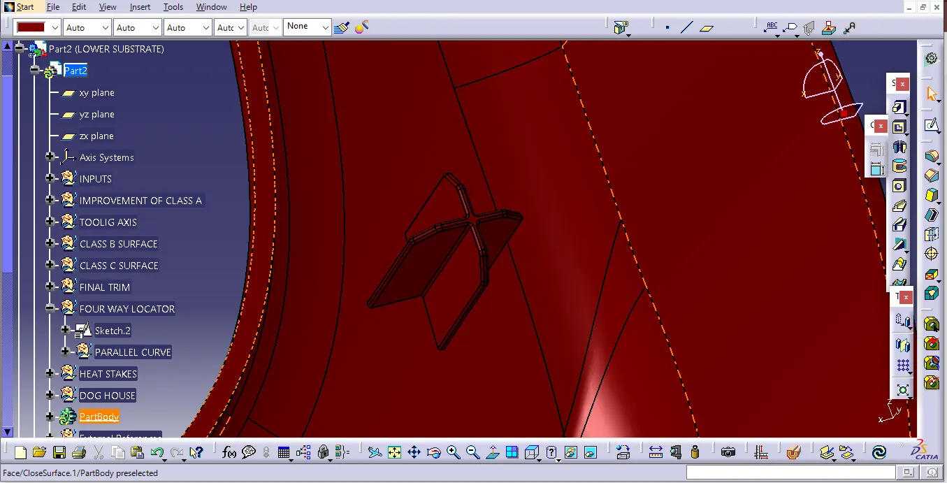
To create a locator following the specified instructions:
1.Surface Extraction:
- Extract the surface where the locator will be created.
2.Positioned Sketch:
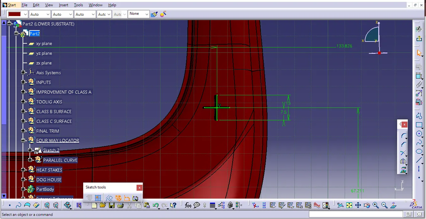
- Use a positioned sketch and draw the required locator sketch.
3.Pad Command:
- Utilize the Pad command for the sketch until the desired height is achieved.
4. Drafting:
- Apply a draft to the locator, ensuring a minimum of 0.5 degrees.
5. Fillet:
- Add a fillet of 0.5mm to all faces of the locator.
6. Assembly:
- Assemble the locator to the lower substrate solid.
7. Maintain Minimum Distance:
- Ensure a minimum of 50mm separation between two locators.
8. Translation:
- Translate the locator to the desired position.
9. trimming Heat Stakes:
- Trim all heat stakes with the lower substrate solid.
10. Height Maintenance:
- Maintain a height greater than that of the heat stakes.
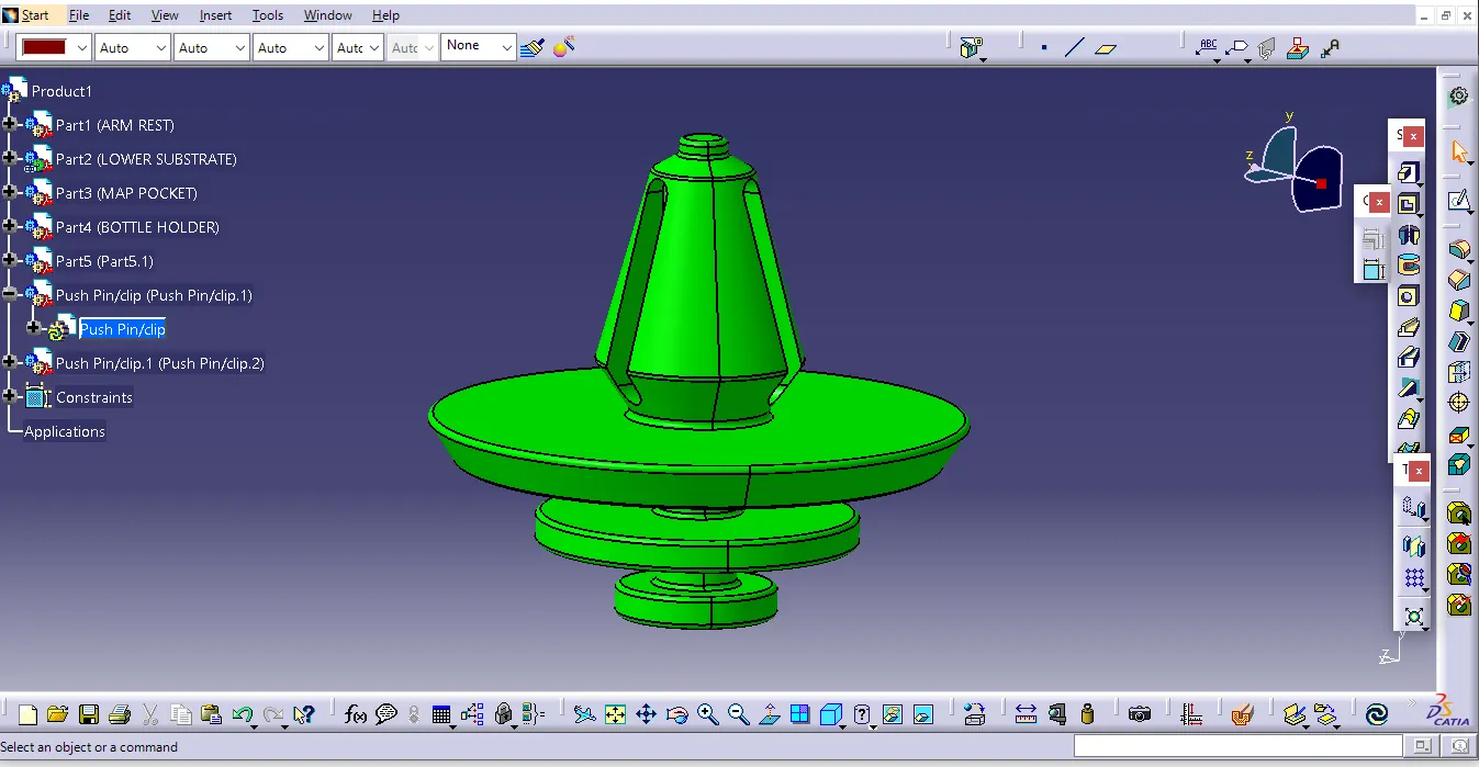
PUSH PIN
FINAL DRAFT ANALYSIS
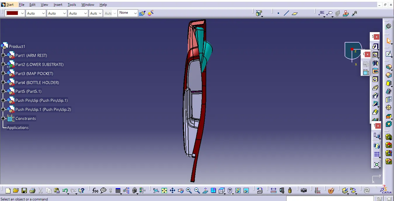
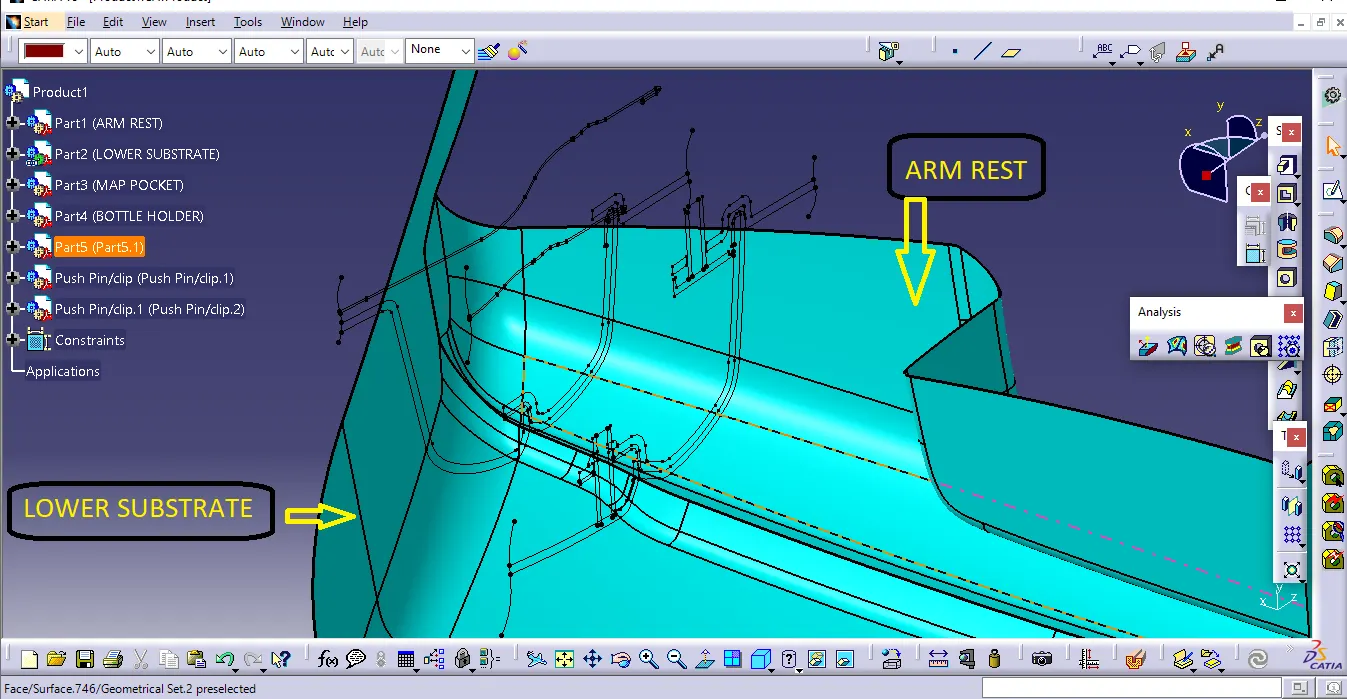
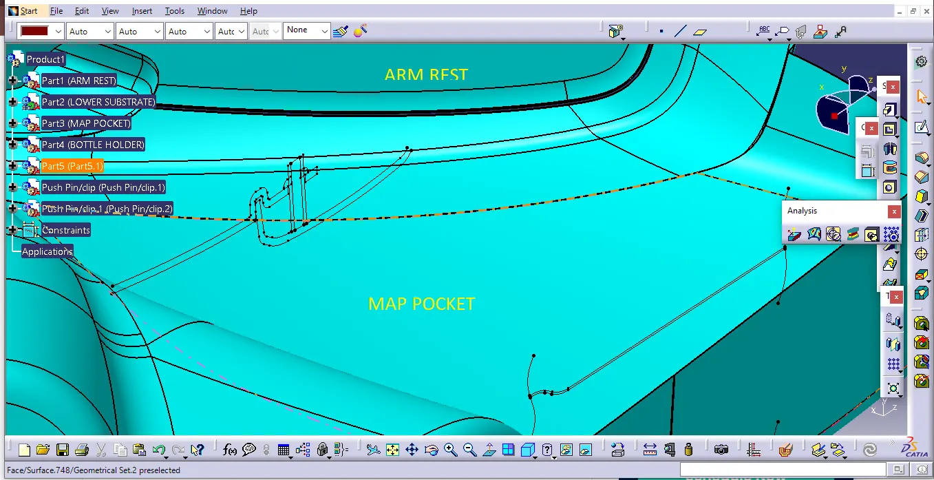
ARM REST
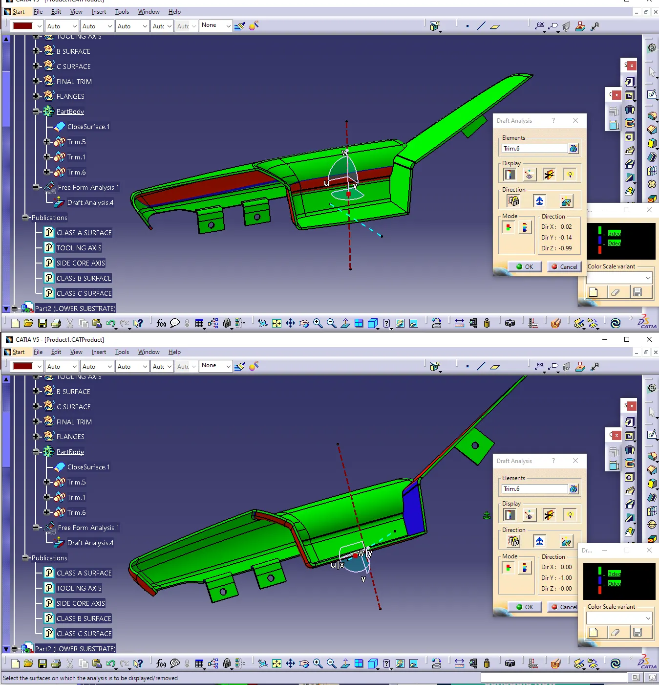
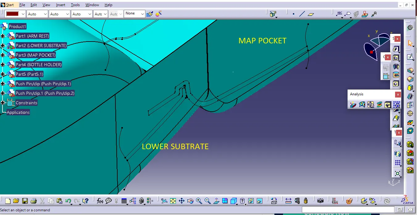
LOWER SUBSTRATE
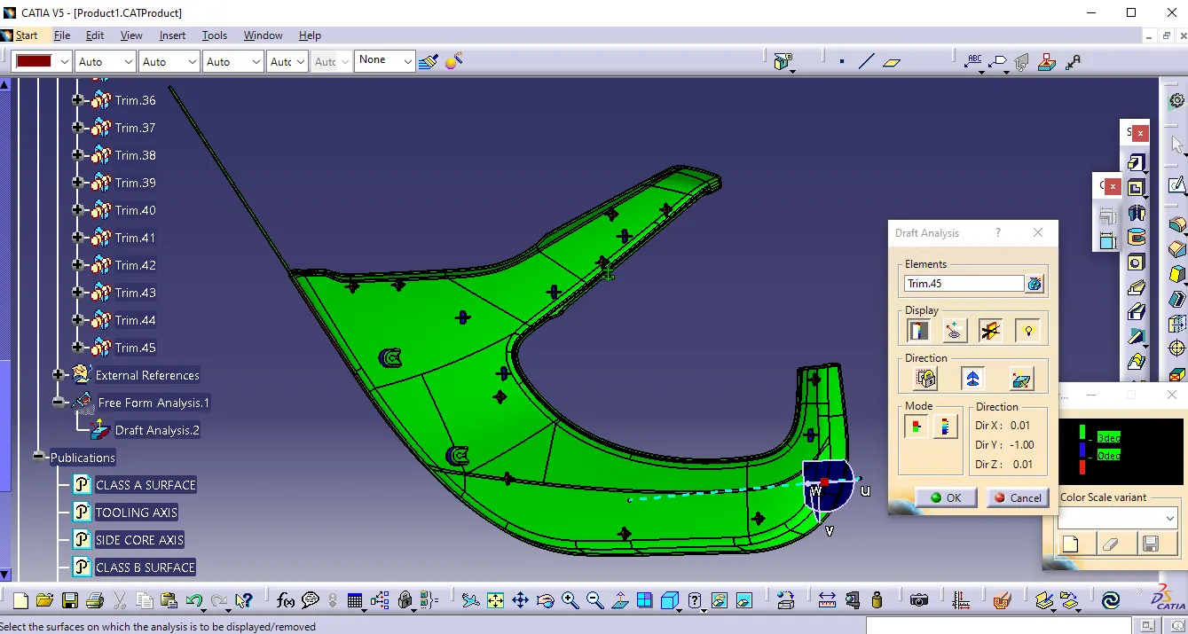
MAP POCKET
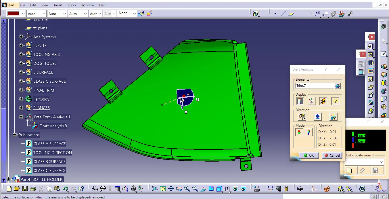
BOTTLE HOLDER
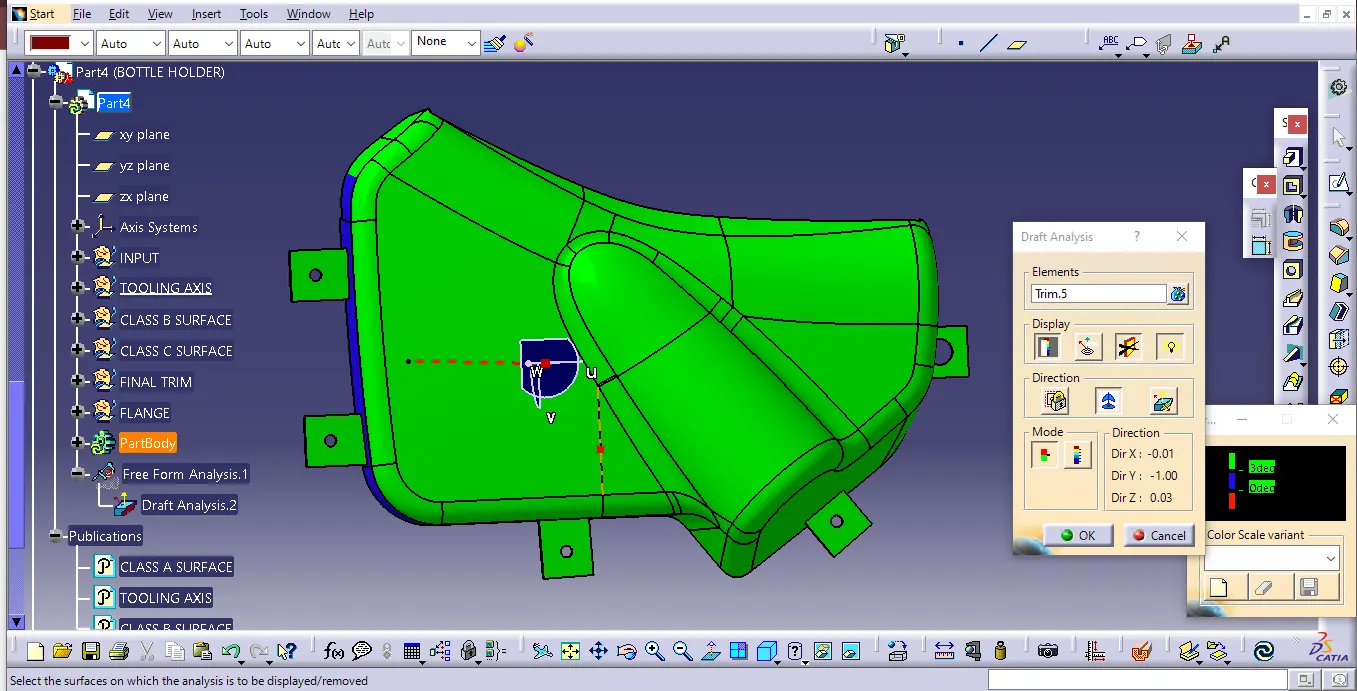
ASSEMBLY CONSTRAINTS FOR PUSH PIN ASSEMBLY OVER DOG HOUSE
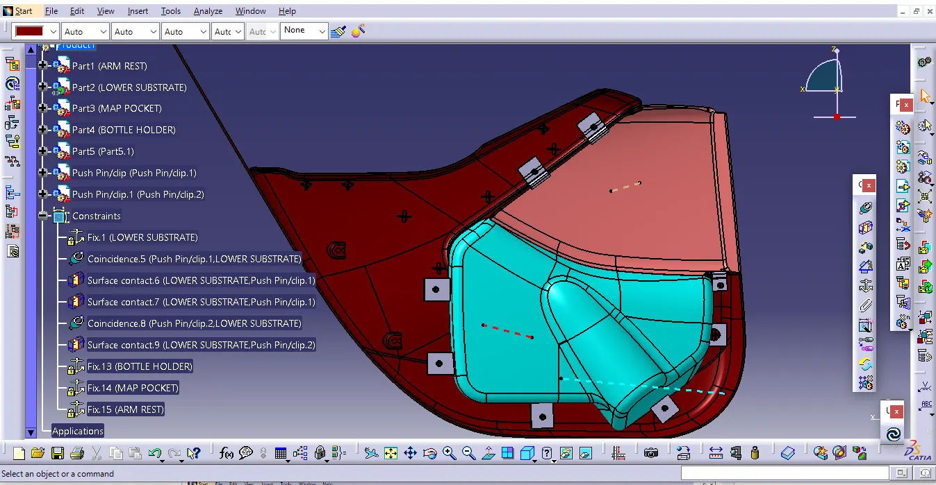
- Screenshots of the solid model with the proper color code of the draft angle in various orientations (Isometric, Front, Side, and Top View)
ISOMETRIC VIEW
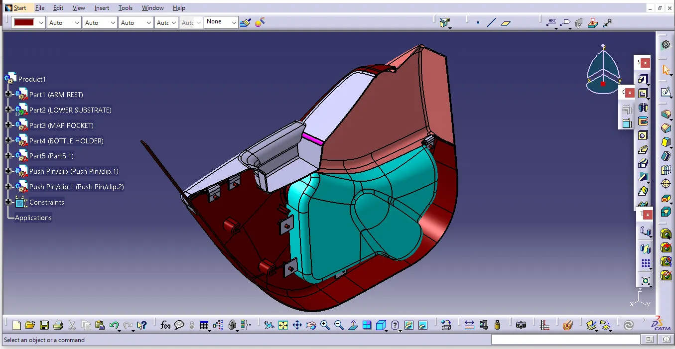
FRONT VIEW
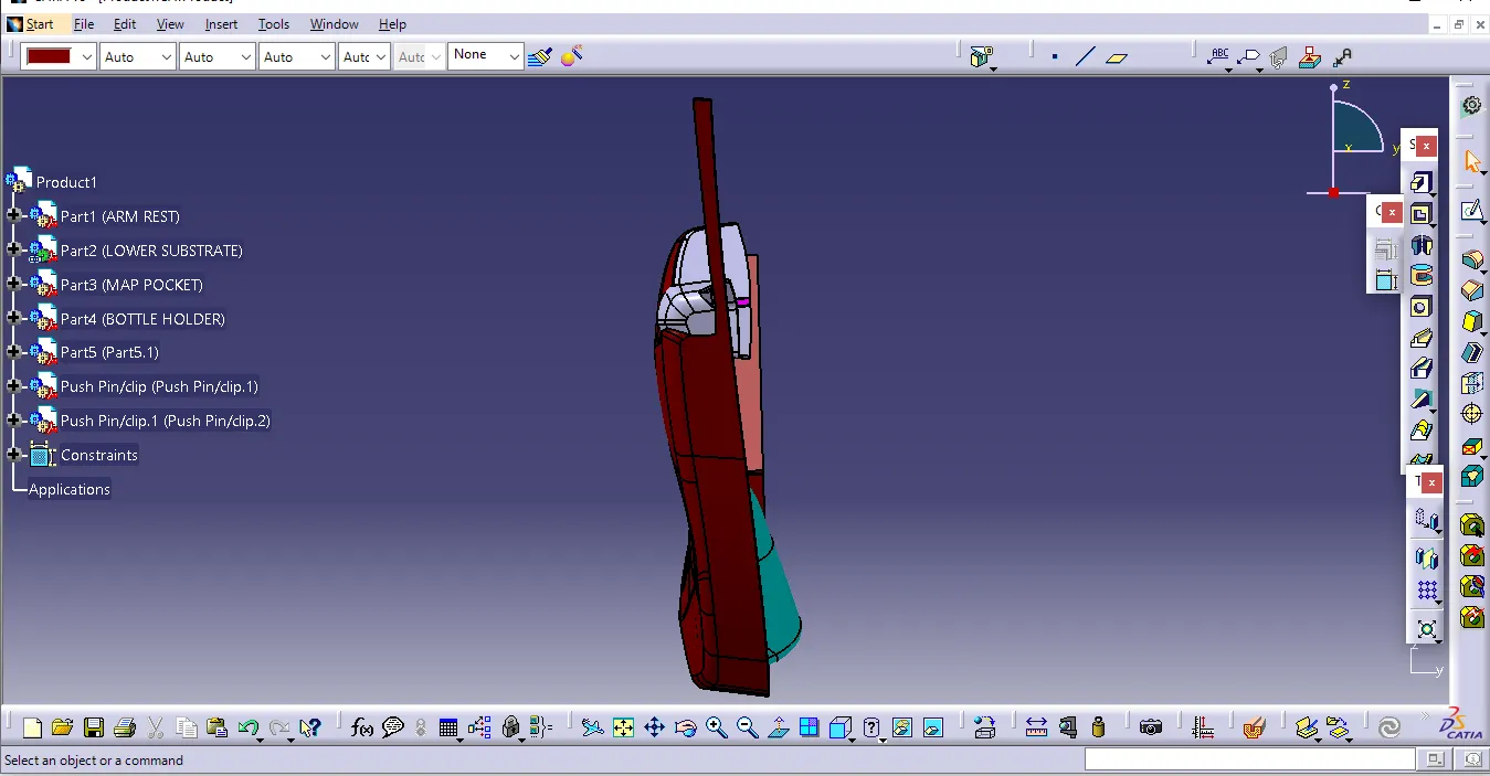
SIDE VIEW
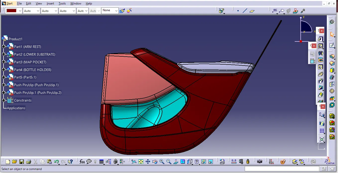
TOP VIEW