Week 10 - Challenge 1- Attachment Feature Creation (Ribs & Screw Boss)
RIBS AND SCREW BOSS
11/10/2023
Shanil kumar K S
TABLE OF CONTENTS
1.Introduction
2.methodology
3.Analysis and Validation
4.Specifications
5.conclution
1. INTRODUCTION
This report outlines the design and creation of a rib and a screw boss for the Drill Handle, adhering to design rules and best practices. The report also explains the methodology of tooling axis creation, specifically using the Bisecting method.
2.METODOLOGY
The draft analysis was performed using CATIA software. The model was examined for draft angles to ensure that it adheres to the specified design requirements.
3.ANALYSIS AND VALIDATION
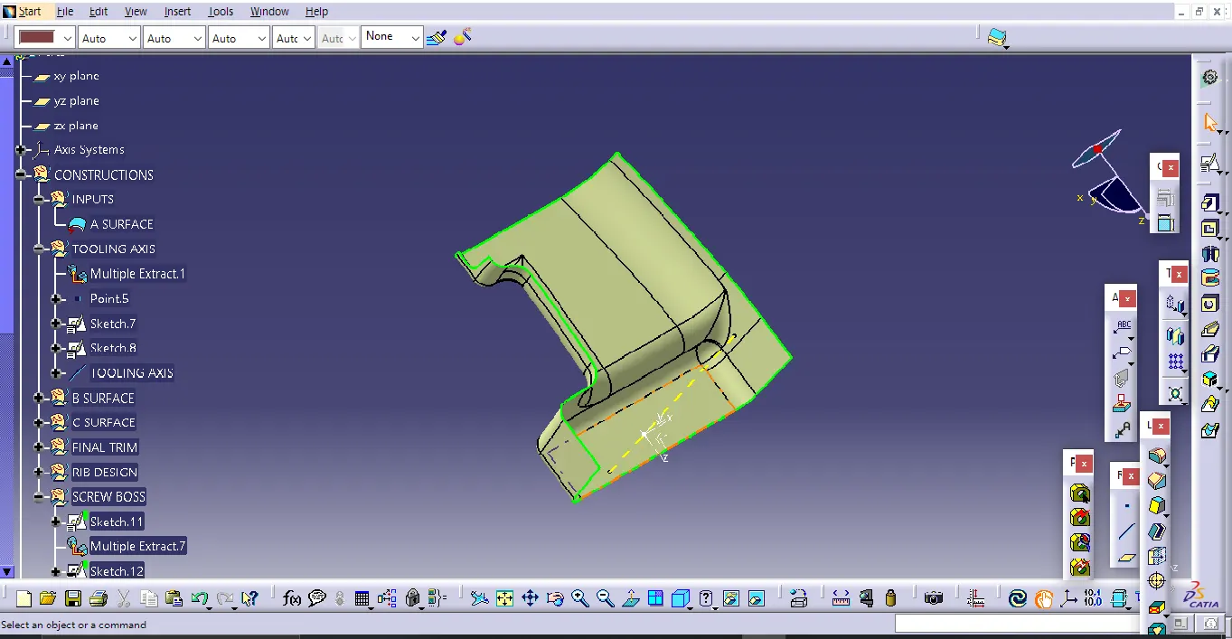
- TOOLING AXIS CREATON - BISECTING METHOD
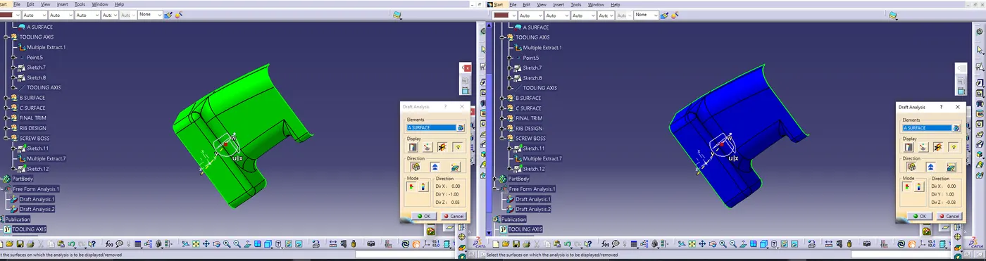
- DRAFT ANALYSIS ON CLASS A SURFACE
Apply the draft analysis tool in CATIA V5 software to the Class-A surface and the tooling axis created. Ensuring that the draft angle meets the specified requirements (usually based on manufacturing and ejection considerations).
- CREATING CLASS B & C SURFACE
Class B and Class C Surfaces were seamlessly integrated into the design, aligning perfectly with the Class A Surface. Surface quality was prioritized to ensure a smooth, high-quality finish.The class c is jioned with A and trimmed with B to form a closed surface.
- SOLID BODY CREATION
Inside the "PART BODY" , the "Close Surface" feature was used to generate a solid body from the Class-A surface, ensuring a consistent thickness.
- CREATING B SIDE FEATURES
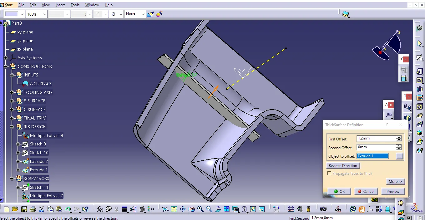
RIBS
Ribs, a common feature in plastic injection-molded components, are slender extensions that extend perpendicularly from a surface or plane. They serve the primary purpose of enhancing the structural support and strength of the part.
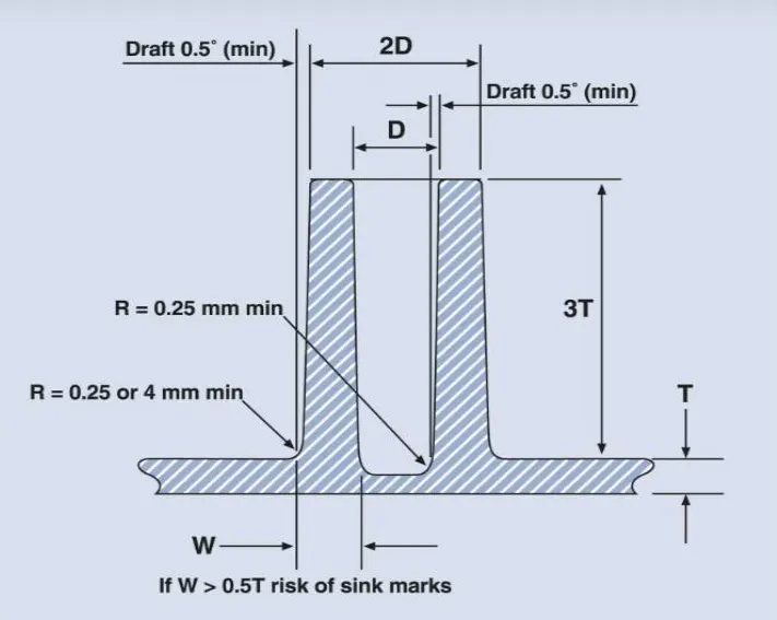
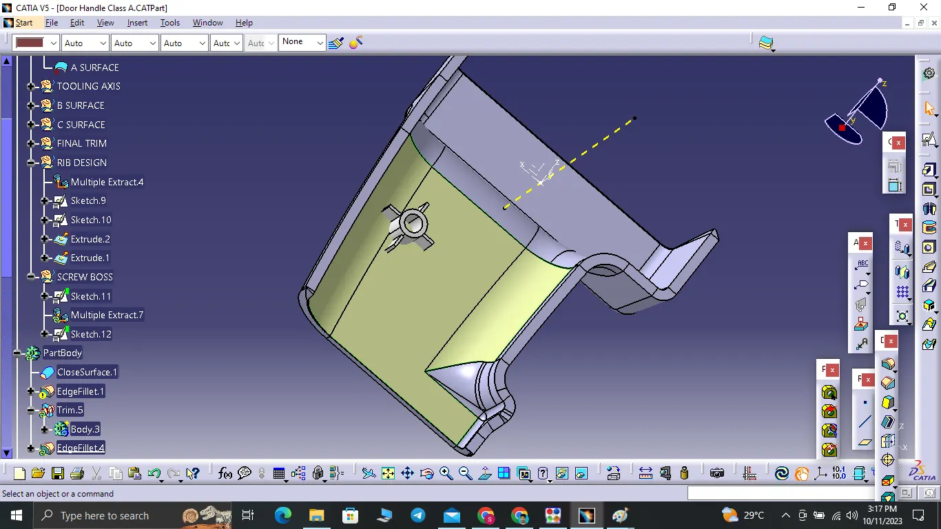
SCREW BOSS
Boss features are frequently encountered in the design of injection-molded components. They serve the purpose of facilitating the assembly of molded parts by creating a pathway for a screw.
DRAFT ANALYSIS OF FINAL PART:-
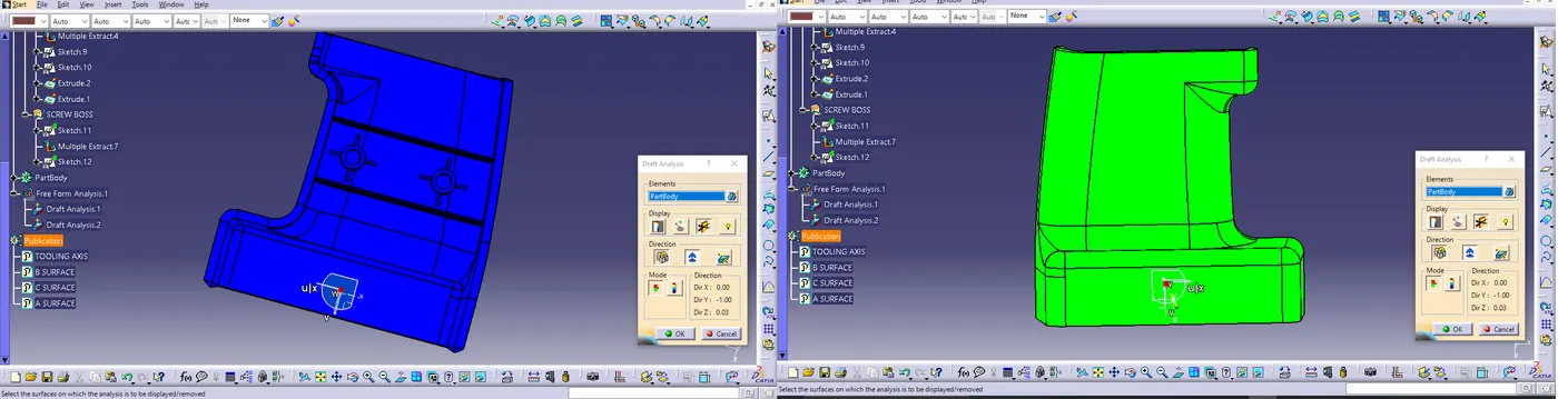
The draft angles throughout the Door handle component were carefully reviewed. It was observed that the draft angles consistently met the specified requirements of 3 degree. This ensures that the component can be easily removed from the mold during manufacturing.
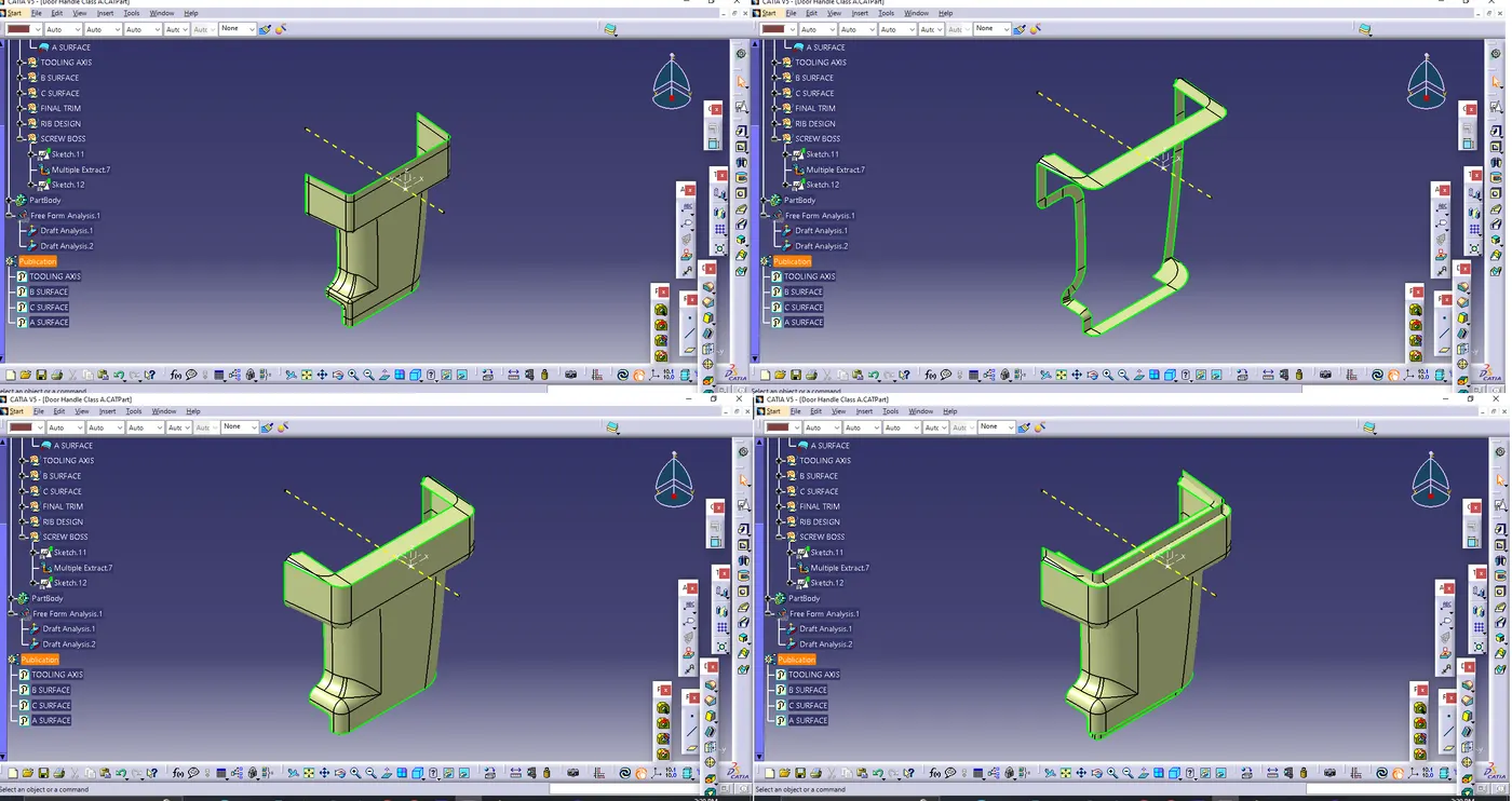
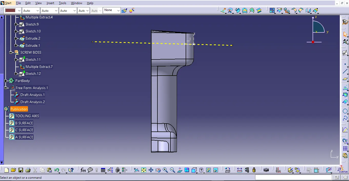
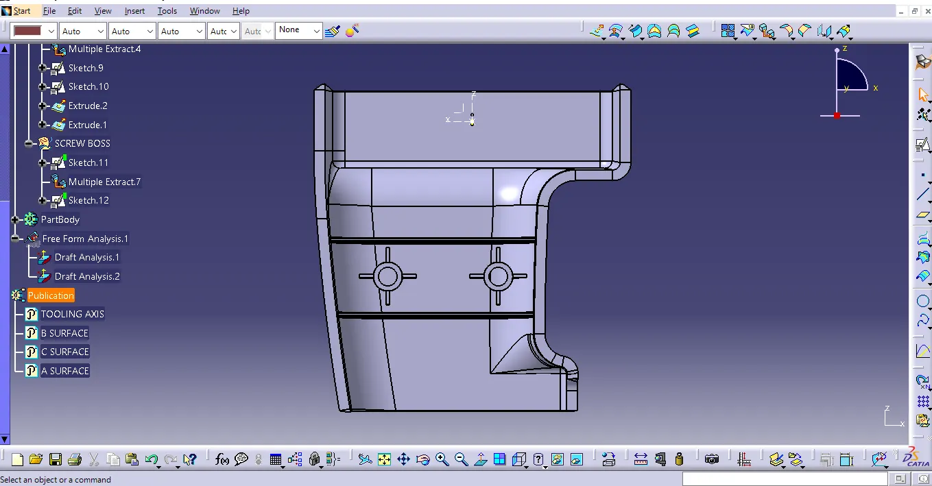
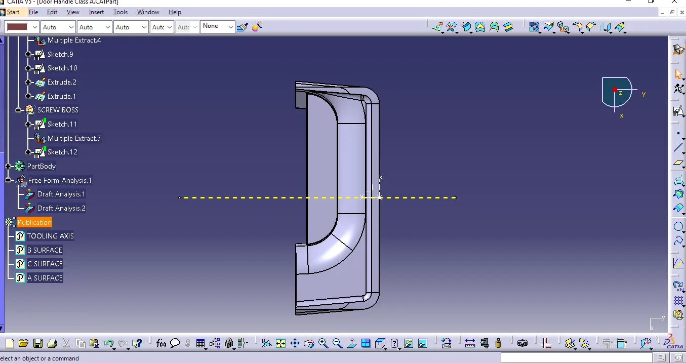
- Screenshots of the solid model with the proper color code of the draft angle in various orientations (Isometric, Front, Side, and Top View)
- ISOMETRIC VIEW
O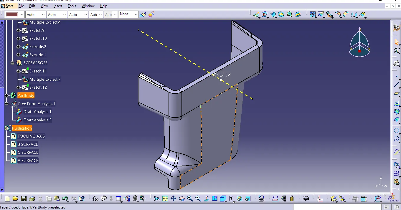
FRONT VIEW
SIDE VIEW
TOP VIEW
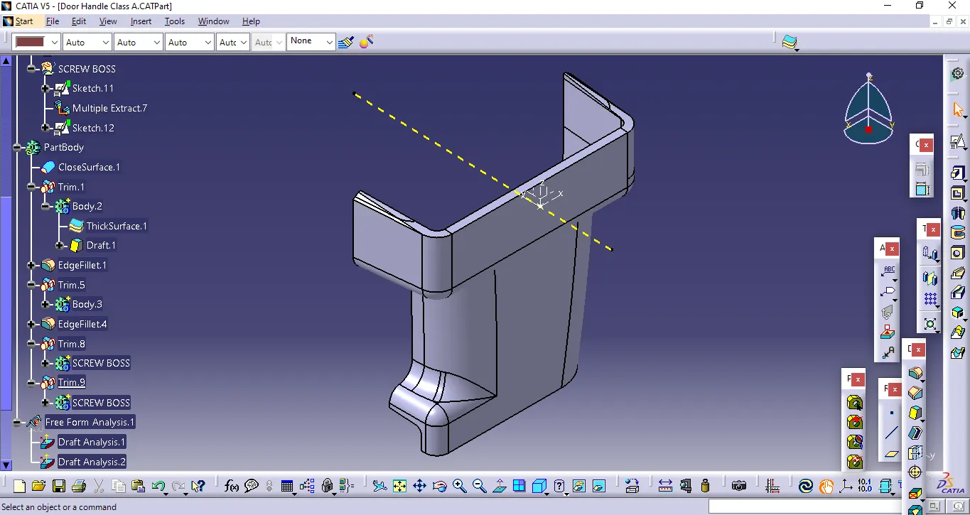
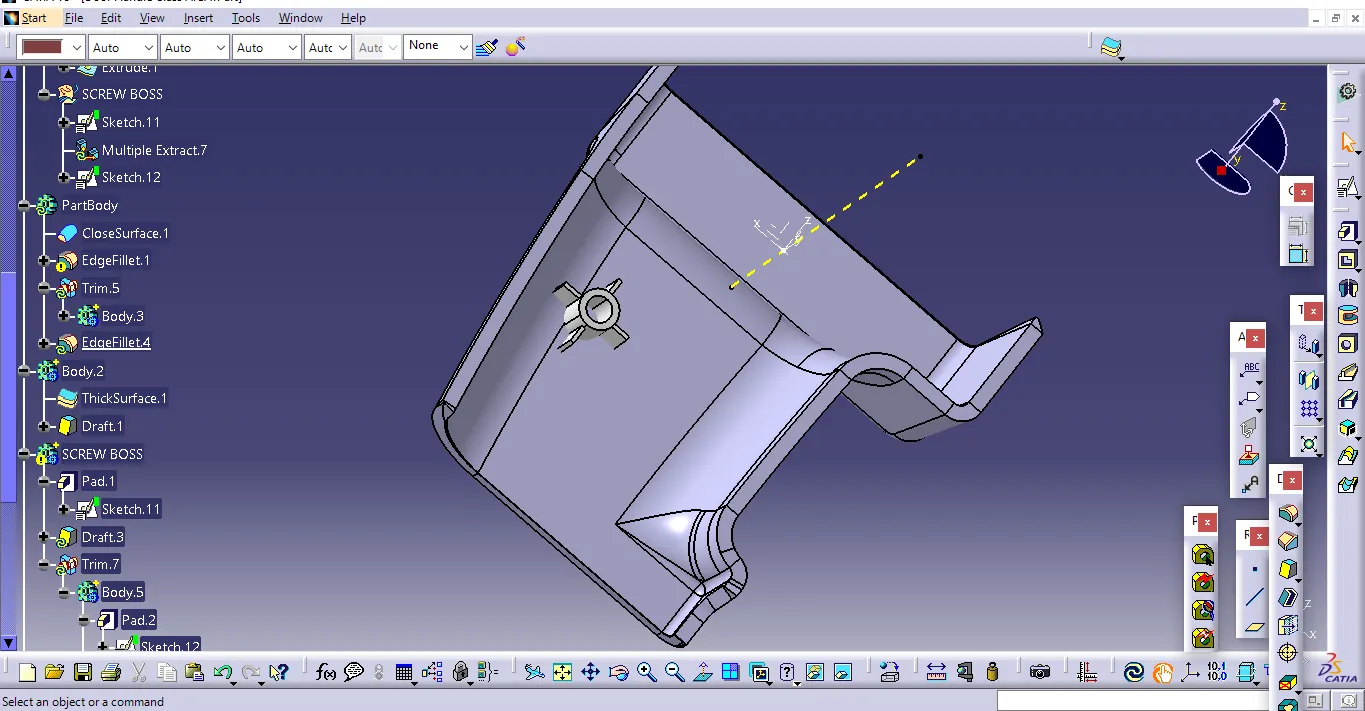
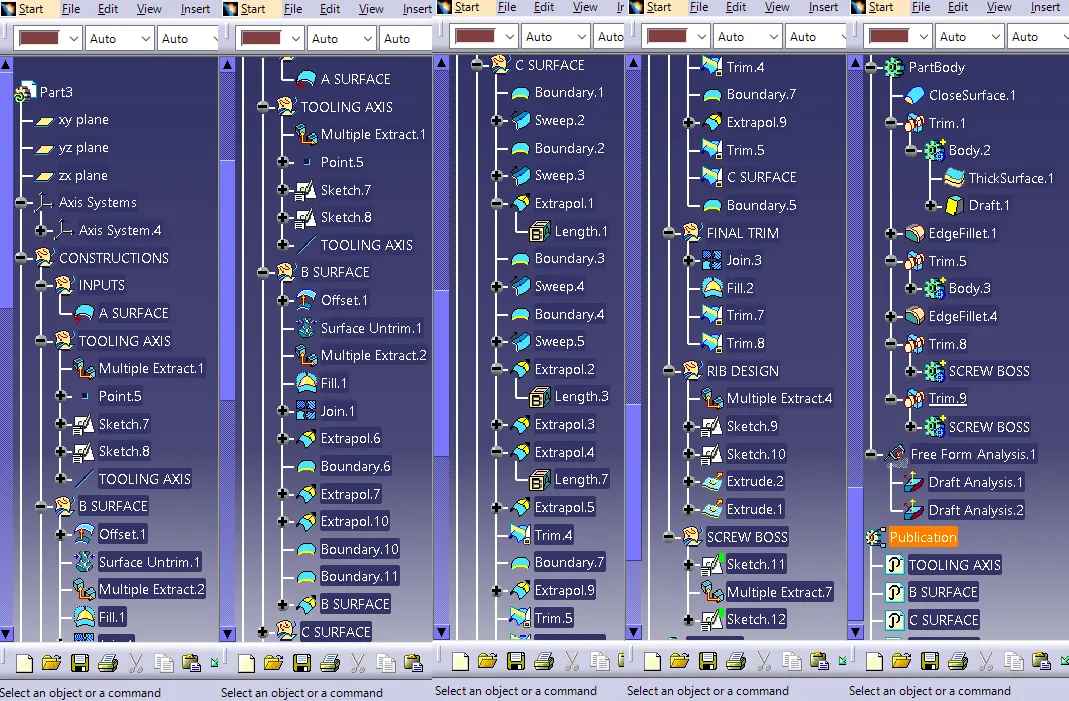
- Expanded Specification Tree (after completion of all steps):
4.SPECIFICATIONS
the parts are drawed with the following specifications
length = mm
angle = degree
time = seconds
5.CONCLUTION
The design of rib, screw boss and analysis of the Door handle Plastic component have been successfully completed, meeting the requirements for Class-A surfaces, draft angles, and manufacturability. The Bisecting method was instrumental in creating the tooling axis with precision.