Week 9 - Challenge 1 - Base Bracket Design
CREATION OF THE BASE BRACKET PLASTIC COMPONENT
4/10/2023
Shanil kumar K S
TABLE OF CONTENTS
1.Introduction
2.methodology
3.design process
4.Specifications
5.Analysis and Validation
6.conclution
1. INTRODUCTION
This report presents the results of a draft analysis performed on the Base Bracket plastic component. The draft angle is the taper applied to the walls of injection molded plastic parts to assist part ejection from the mold. A sufficient draft angle is essential to prevent the part from sticking to the mold and to ensure a good surface finish.
2. METHODOLOGY
The draft analysis was performed using the CATIA V5 Draft Analysis tool. This tool calculates the draft angle of each surface in the model and compares it to the specified minimum draft angle.It displays various draft angles at different locations and indicates their compliance or non-compliance through different color codes.The default minimum draft angle is 3 degree.
3. DESIGN PROCESS
The Class-A surface was imported into the CATIA V5 software.
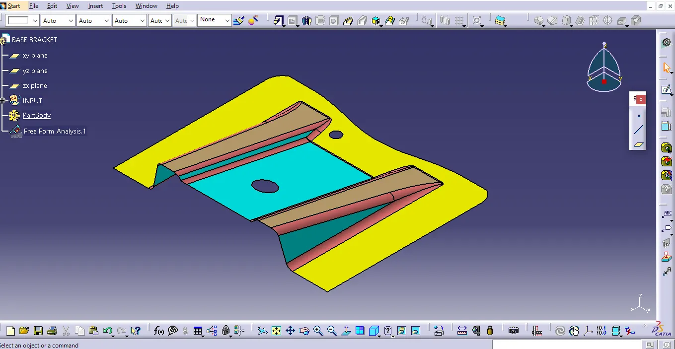
Steps involved in analysis:
a) Determining and creaing the Tooling Axis
- Checkig the bondary
The initial step involves inspecting the provided section's boundary to identify any gaps, openings, or discontinuities within it. In the case of multiple boundaries resulting from openings, they can be distinguished from one another.
- adding a coordinate system
To proceed with the other steps, start by placing a point near the nearly symmetrical center of the part, and then establish a coordinate system at that point. Ensure that the newly inserted coordinate system aligns in all directions, just like the default coordinate system.
- Determining a tooling axis
The tooling axis is determined by examining the part from various angles, considering factors like cost-effectiveness and the avoidance of side cores.
- Intersect with the yz plane:
After determining the tooling axis, we must find where the tooling axis intersects the part in two directions other than its own axis. We first use the xz plane to locate the intersection curve. Then, we examine the curve elements that may cause issues during part ejection. Curves that are nearly perpendicular or at a steep angle to the tooling axis should not pose a problem, as they can be easily ejected. However, if the intersection curve contains elements that are nearly parallel or at a shallow angle to the tooling axis, we should assess them using the bisecting line.
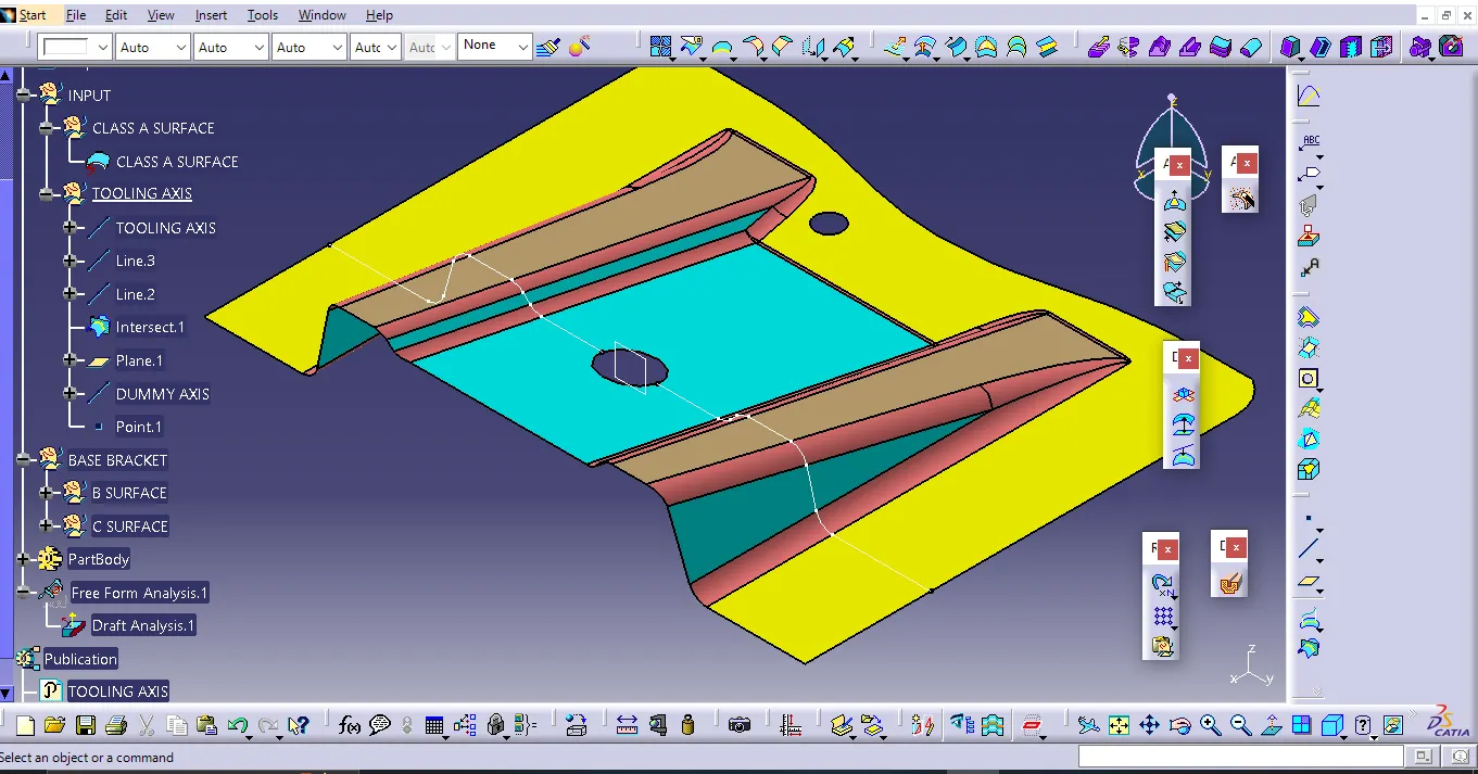
- creating a dummy tooling axis
A dummy tooling axis is created with the assistance of the previously established point before actually creating the tooling axis.
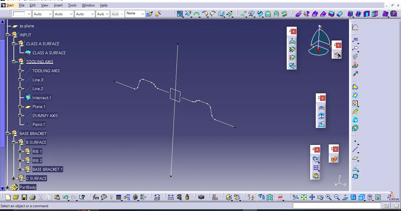
- creating lines with repect to steep curve
As previously mentioned, we need to evaluate the intersection curve elements that seem parallel to the dummy tooling axis. To achieve this, we take their endpoints and draw lines through them on both sides of the axis.
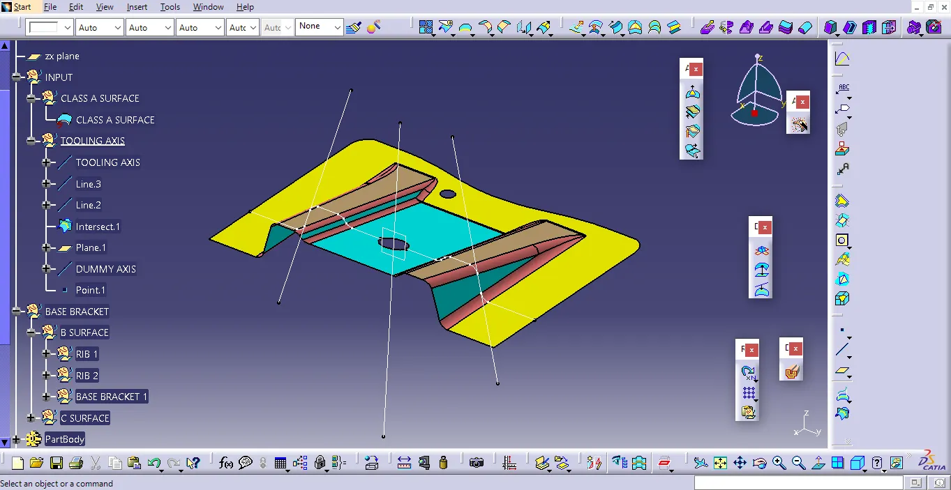 A b ) tooling axis was created using the bisecting method and publishing tooling axis
Publishing elements in CATIA V5 serve multiple purposes, such as establishing part references as datum entities. In this case, we've published the base bracket surface and the tooling axis.
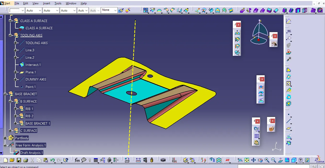
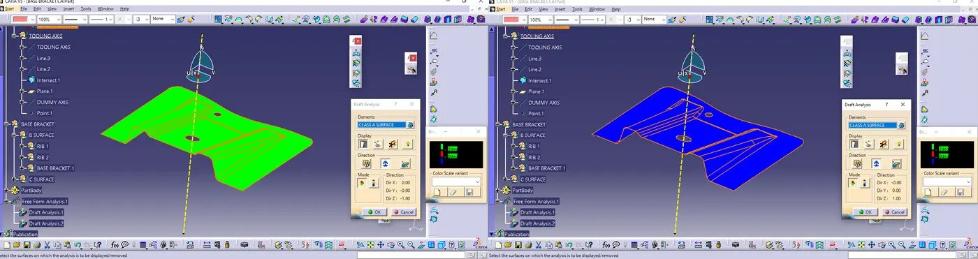
- To Perform the base bracket draft analysis by following these steps:
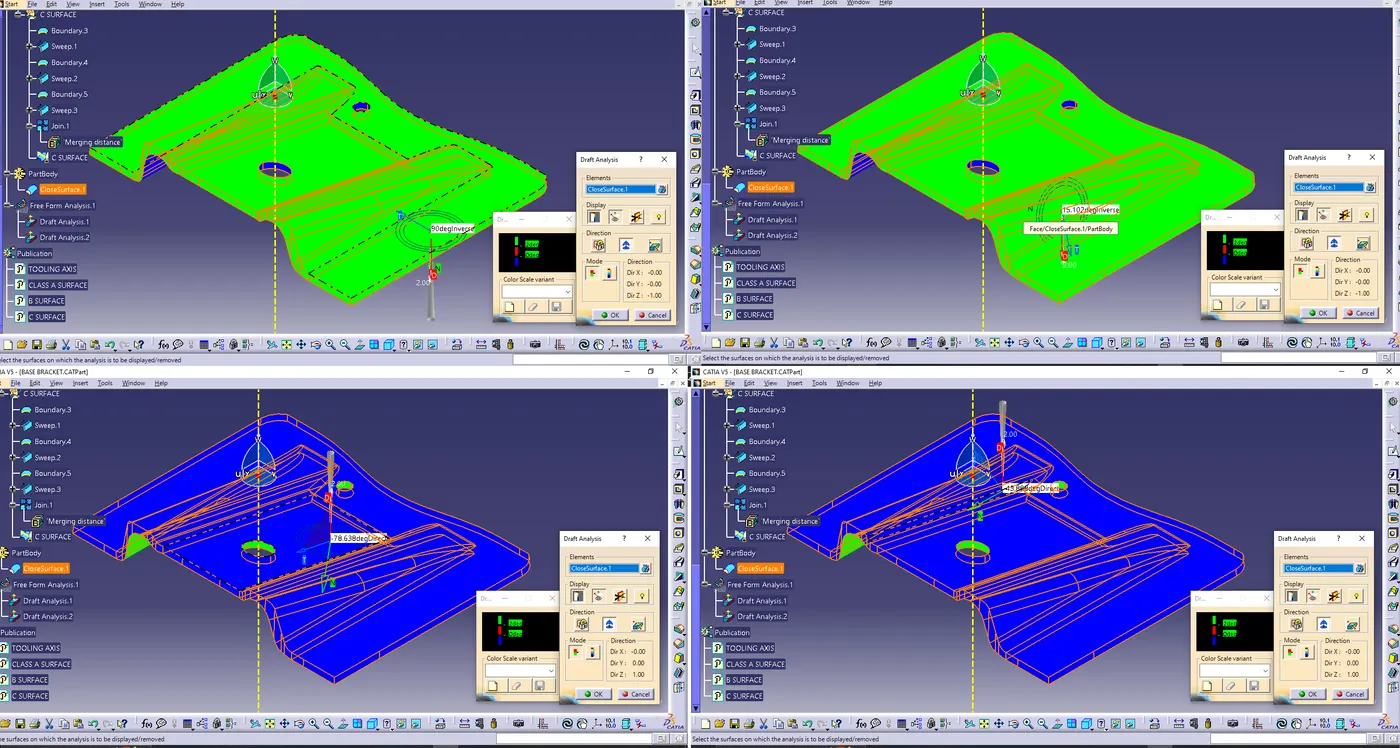
Navigate to Insert > Analysis > Feature Draft Analysis. Within the Feature Draft Analysis tool, you'll find three sets of options like mode, display, and direction. First, select the second icon from the direction group. Click and drag the red dot in the compass to the part want to analyze for draft. Align the line in the dragged element with the tooling axis. Lock the alignment by using the first icon in the direction group. This defines the tooling axis direction. Click on the base bracket want to analyze. The base bracket will change color, turning green or displaying both green and red based on the draft angles present. If the minimum draft angle is set to 3 degrees and the bracket has only 2 degrees of draft angle, that portion will be highlighted in red. If the portion has enough draft angle, it will appear in green. This completes the draft analysis of the base bracket.
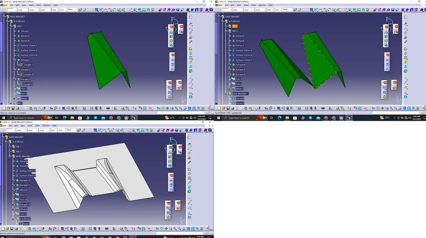
- The Class-B surfaces were created by offsetting the Class-A surface by the thickness of the plastic part (2.5 mm) in the tooling axis direction.
- The Class-C surfaces were formed by trimming the combined Class-A and sweeping them with a draft direction towards the Class-B surface, matching the plastic part's thickness (2.5 mm) in the tooling axis direction.
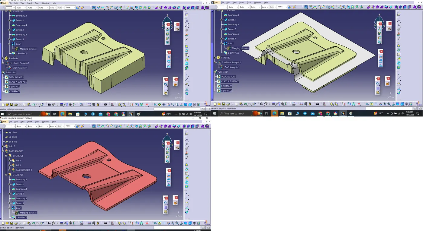
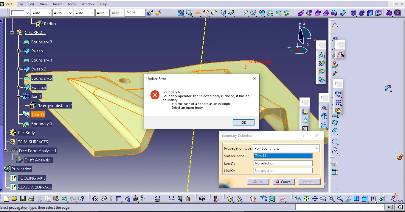
- ensure the surface is closed surface by using Boundary feature
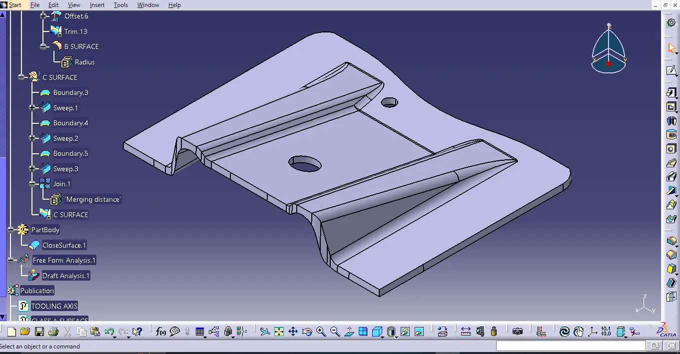
- A solid body was created from the Class-A, Class-B, and Class-C surfaces using the Close Surface feature.
- A draft analysis was performed on the model to ensure that all of the surfaces had a draft angle of at least 1 degree.
- Screenshots of the solid model with the proper color code of the draft angle in various orientations (Isometric, Front, Side, and Top View)
isometric view
front view
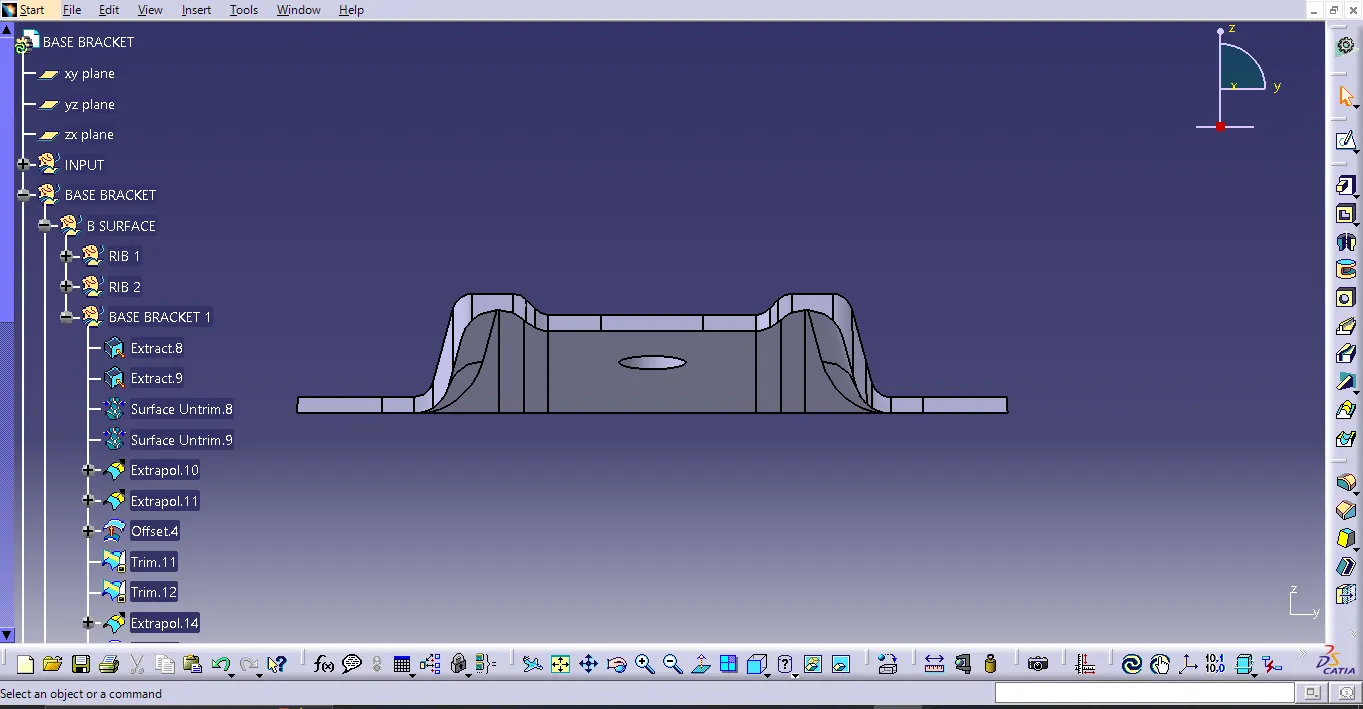
side view
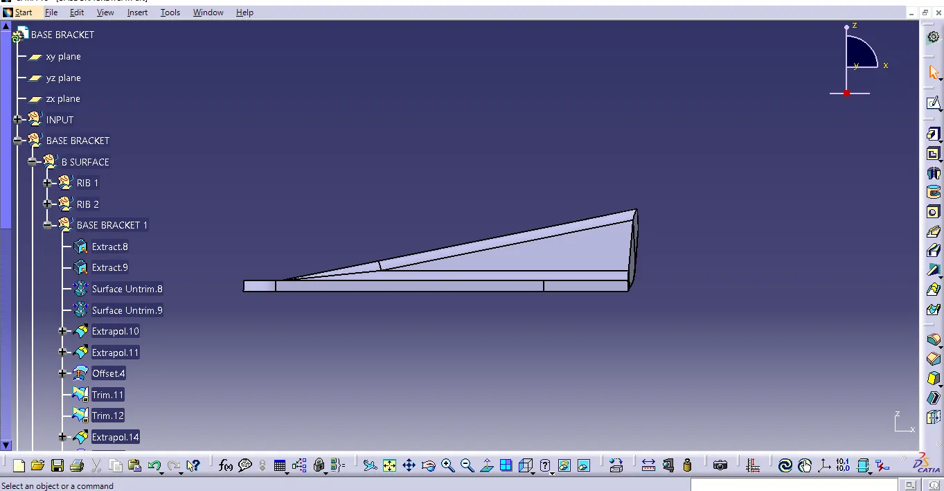
top view
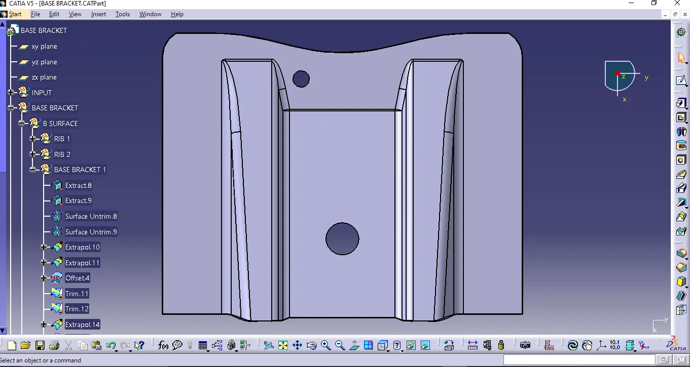
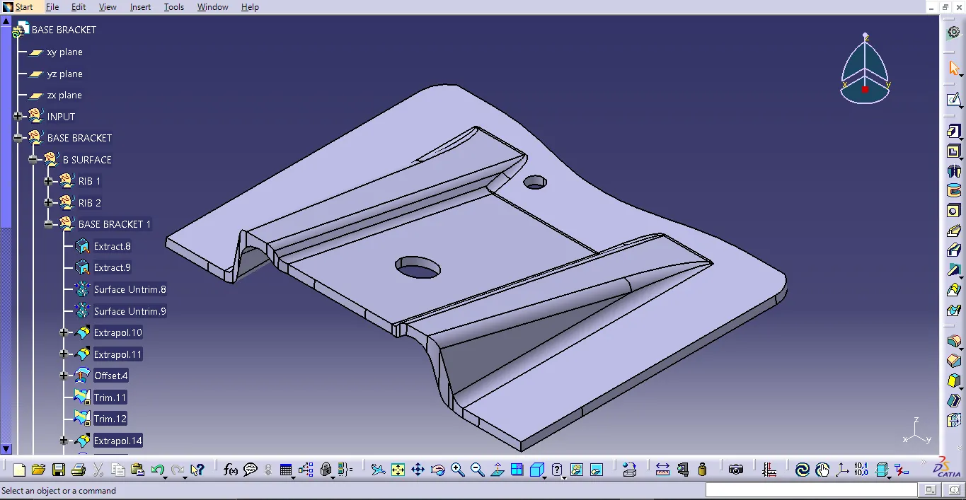
Expanded Specification Tree (after completion of all steps):
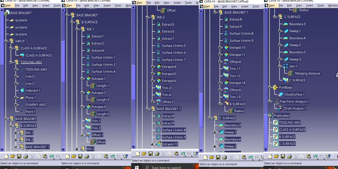
4.Specifications
the parts are drawed with the following specifications
length = mm
angle = degree
time = seconds
5.Analysis and Validation
Ensured Proper Tree Structure Geometrical sets should have a proper name based on the sketches present inside of it .ensured all the sketches should be created under the Geometrical set Use the Close Surface feature to make a solid body from the surface. Used the publication option and publish the below Tooling Axis Class A, B, and C surface.The draft analysis of the Base Bracket plastic component showed that all surfaces have a draft angle of minimum 3 degree, which is sufficient for injection molding. The tooling axis was created using the bisecting method, which is a simple and effective way to ensure that the part can be ejected from the mold without sticking.
6.conclution
The draft analysis results show that the Base Bracket plastic component is moldable with a good surface finish. No further changes are required to the model.