Week 12- Final project
Aim: To develop a Door Trim Panel from the Given Class A surface and also to attach all the required B Surface Attachment Features.
Description:
- In this project is a brief explanation of how the Door trim Panel of a car is developed as per industrial standards by following all the design rules for creating the Class B surface and Class C surface and all the attachment features.
- This report explains the creation of the tooling axis and performing the draft analysis.
- All the Dimensional and design considerations for creating the attachment features are mentioned in this report.
Master Sections:
- The Master section is the Guideline for the creation of the Class B surface and also demonstrates the location of the fixation features located on the B side of the plastic component.
Class- A Surface:
- In automotive design, a class A surface is any set of freeform surfaces of high efficiency and quality.
- It is the visible aesthetic surface of any automotive component.
- Class A surface refers to those surfaces which are visible and abide by the physical meaning, of a product.
- This classification is primarily used in the automotive and increasingly in the consumer goods industry.
- It is a requirement where aesthetics has a significant contribution.
- For this reason, the exterior of automobiles is deemed Class-A.
Class- B Surface:
- Class B surfaces are Engineering Surfaces that are invisible to the eyes or often on the back side of the Class A surfaces.
- It is mainly the thickness of the component or Class A.
- These surfaces need to be designed as per the Class A surface i.e., the continuity, thickness of the component, functionality, etc should be maintained.
- These surfaces include the main engineering features such as Screw bosses, Ribs, Snaps, Stiffeners, and fixations.
- B surfaces also do not contain any aesthetic styling content and textures since it is not visible to the eyes.
Class- C Surface:
- Class C surfaces are connectors between Class A and B surfaces.
- This surface connects both A and B surfaces at a certain draft angle to the Tooling Axis.
- It contains the draft as per the design.
- It is basically the thickened surface between both A and B surfaces.
Design of the Door Trim Panel:
- This Door Trim Panel consists of four parts namely
1. Door Armrest
2. Lower Substrate
3. Map Pocket
4. Bottle Holder
- An armrest offers the possibility of comfortably positioning your hand when driving on a motorway or standing in traffic.
Lower Substrate:
- Lower Substrate is the encapsulating aesthetic Part used in the door panel. It may house various features such as Wirings, Speakers, and other sheet metal components behind it.
Map Pocket:
- A map pocket structure for a vehicle is provided to prevent the movement of a water bottle while driving and store a variety size of bottles regardless of the size of the bottles.
Bottle Holder:
- The Bottle holder serves to hold the water bottle or things like that.
Tooling axis:
- The Tooling axis is the direction in which the mold opens or else the core and cavity open. The tooling axis should assist to clear components from the core and cavity, so it plays a very crucial role in plastic design and manufacturing also.
- We can also say that the tooling axis is the way followed by the core and cavity while opening and closing so no surface should be intersecting with the tooling axis.
Draft Angle:
- Draft angle is the degree of taper that is incorporated into the side wall and part, core, and cavity of the die-cast tool to aid in the removal of a part. Primarily, their function is to reduce the friction between the part and the tool as it is ejected. Without draft angles, parts can be stripped, dented, or get stuck in the tool.
- Draft angle also reduces the friction between the part, core, and cavity and also reduces the production time as it is easy to eject the part from the core and cavity.
Steps for the development of the Door trim panel:
- Inspection of the given Class A surface and make sure that there are no gaps between the contact of the surfaces within the part.
- Create the Tooling axis for the given class A surface and perform a Draft analysis for the class A surface if needed make necessary changes
- Then develop the Class B surface by using the offset method or extraction of surfaces method
- Create a class C surface from the given Class A surface and with the reference of the Master section for all four parts separately.
- After preparing the Closed part perform a Draft analysis with respective the Main tooling axis.
- Import all four components into the assembly workbench and verify the master section for the attachment features and develop all the required attachment features as per the Design rules.
- Create the constraints for the parts by using the Assembly workbench.
Steps to Develop the Class A surface to Closed Part for a Component our Parts list:
- Always Start with the inspection of the quality of the given class A surface in this inspection we have to make sure that there are no gaps between the contact of the surfaces within the part.
- In the inspection I got some contact gaps between the surfaces and the reference image is shown below.
- For that we have to improve the quality of the Class A surface without changing the dimensions and the improved Class A surface is as shown below.
DETAIL REPORT-
1)CLASS A SURFACE :
- Class-A (or 'Strak') is a term used in specifically in automotive design. It describes the final production surface data for the aesthetic parts of the car.
- The term 'Class A' is often misunderstood, but it's generally seen as the 'Holy Grail' of surface modelling. This is because as it achieves the highest surface quality levels, and it demands a high level of automotive design knowledge as well as surface modelling skills.
- Class A represents the 'craftwork' end of the design process. Creating the main surface shapes to describe the vehicle is the primary design activity. But the painstaking, detailed craftsmanship of perfecting those surfaces, designing flanges and panel gaps is what guarantees that a beautiful design turns into a beautiful manufactured product.
- Here we have four class A surfaces as inputs:
a)ARM REST:
b)LOWER SUBSTRATE:
c)BOTTLE HOLDER:
d)MAP POCKET:
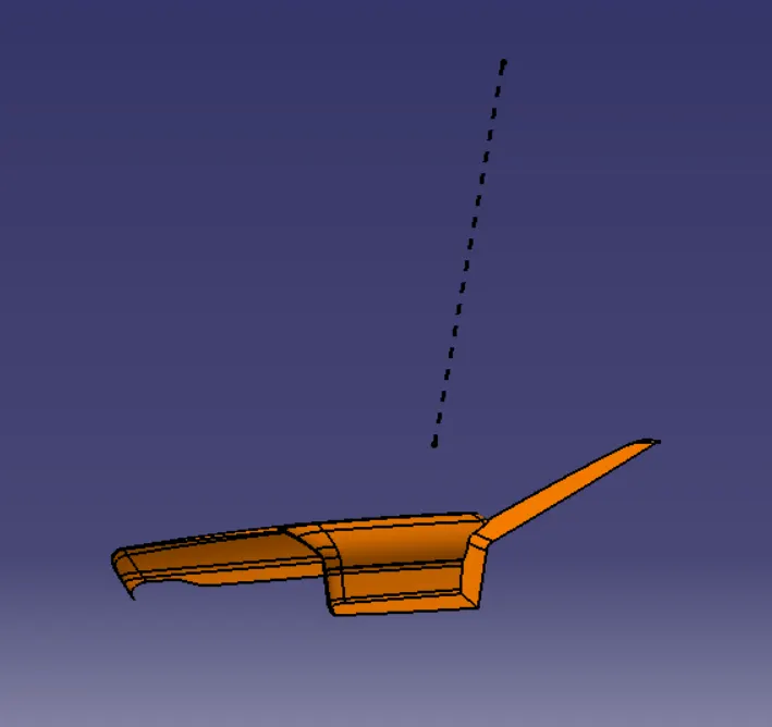
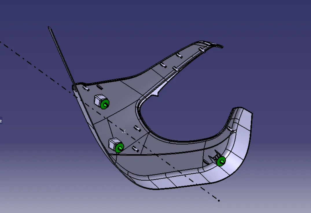
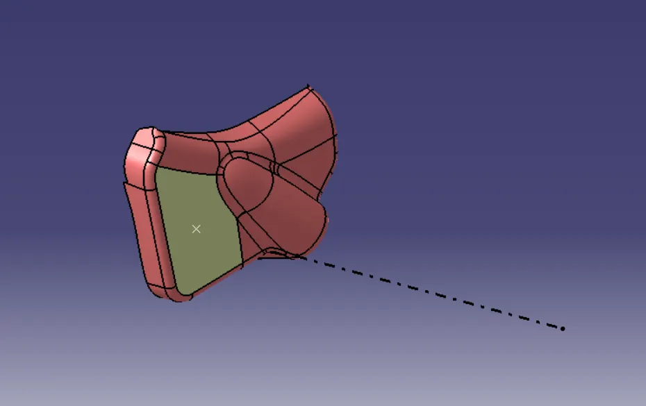
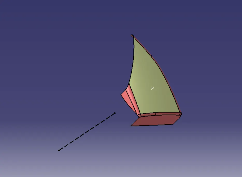
2)TOOLING AXIS CREATION :
- Tooling axis plays important role in plastic product manufacturing and designing, this axis decides the direction in which mould is going to work while production of the component.
- The main focus while deciding the tooling axis is clearing the component in the moulding in the same axis with the minimum use of the side core for producing the component, the side core usually adds up to the cost of the component.
- Here we have used different different method for every component.
a)ARM REST:
b)LOWER SUBSTRATE:
c)BOTTLE HOLDER:
d)MAP POCKET:
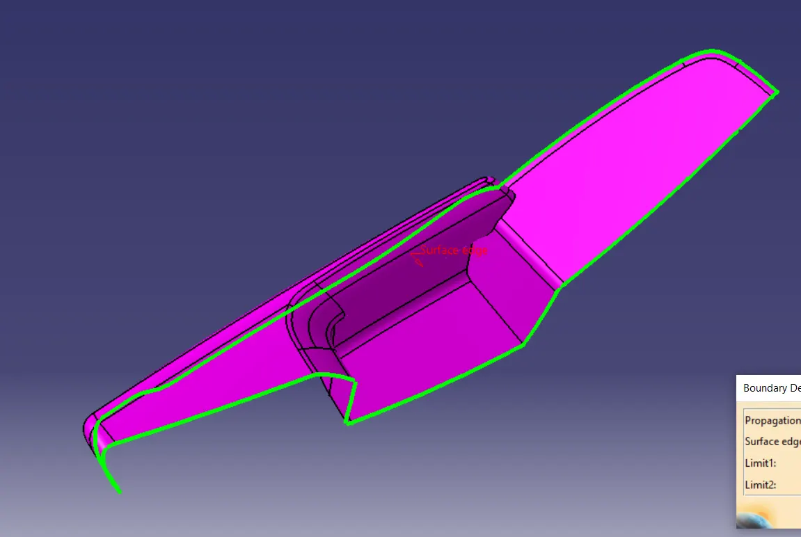
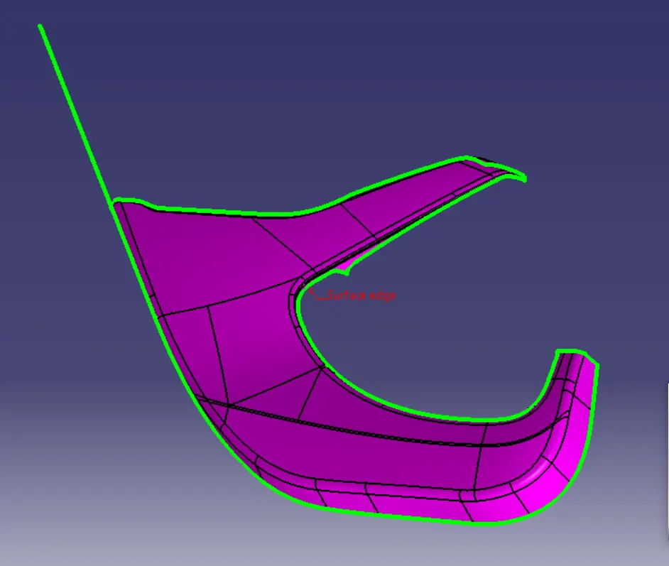
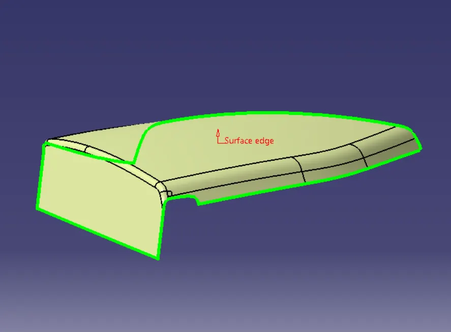
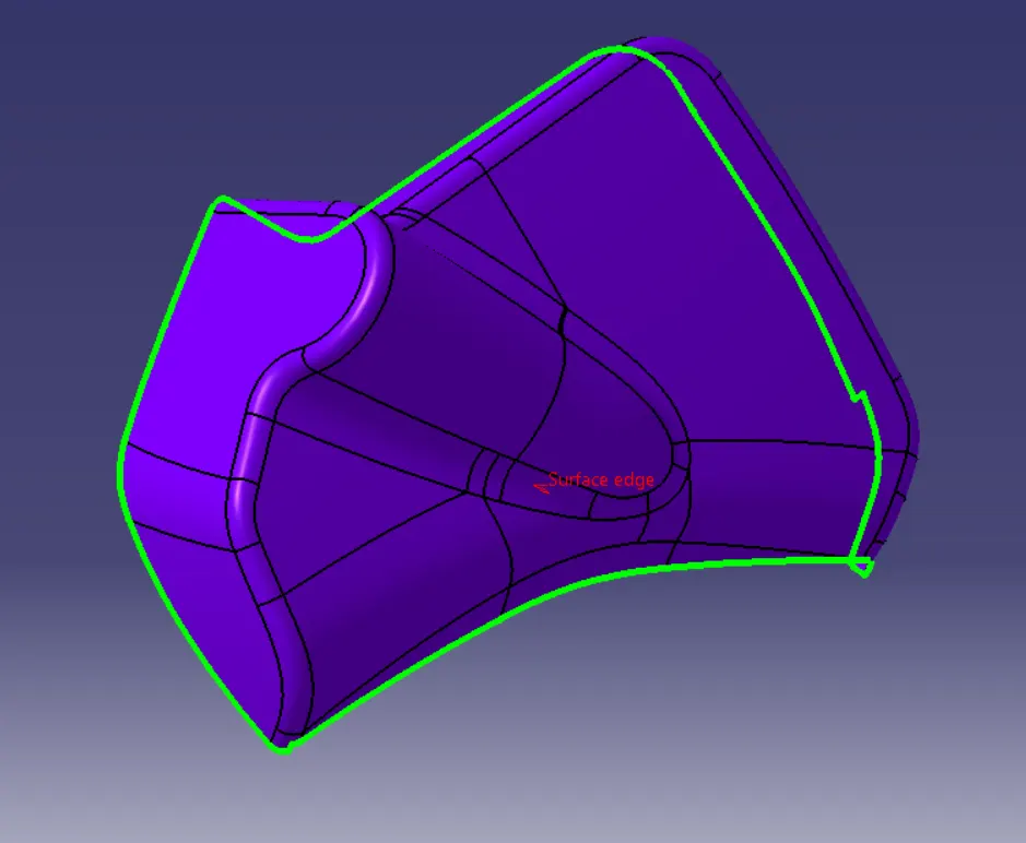
4)CREATING THE CLASS B SURFACE:
- Class B surface is the surface which is created with the help of class A surface as the reference.
- The the class B surface is the surface where all the necessary attachments and supports of the component is made .
- The main parts without the edge fillets are extracted and untrimmed and then they are extrapolated for better view.
- The extrapolated parts are then made offset with reference to the class A with the thickness of the component, here thickness of the component for base bracket is 2.5 mm.
- The offset surfaces are then trimmed to attain the class B surface.
- You can even directly offset the class A for obtaining the class B surface.
- The final class B surface must have the edge fillets similar to the class A and fillets must be given properly with a thought of maintaining same thickness throughout avoiding the flow line defects.
a)ARM REST:
b)LOWER SUBSTRATE:
c)MAP POCKET:
d)BOTTLE HOLDER:
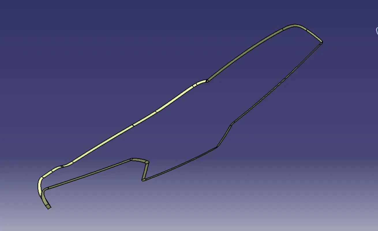
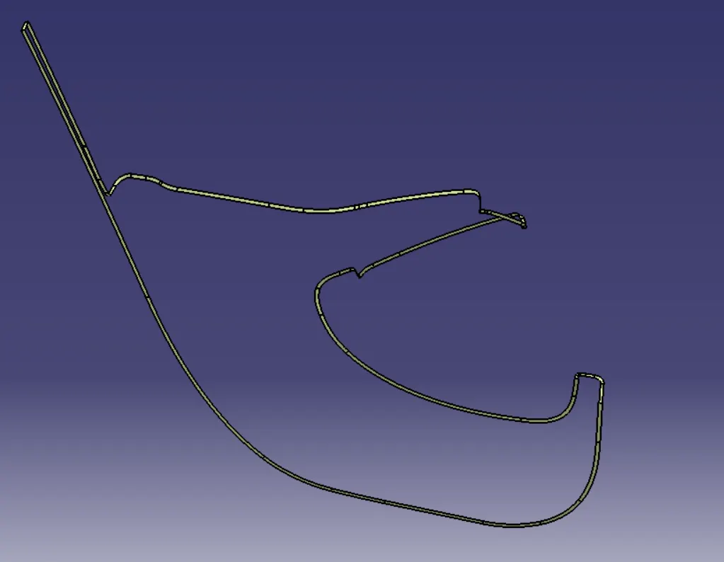
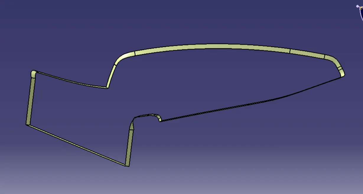
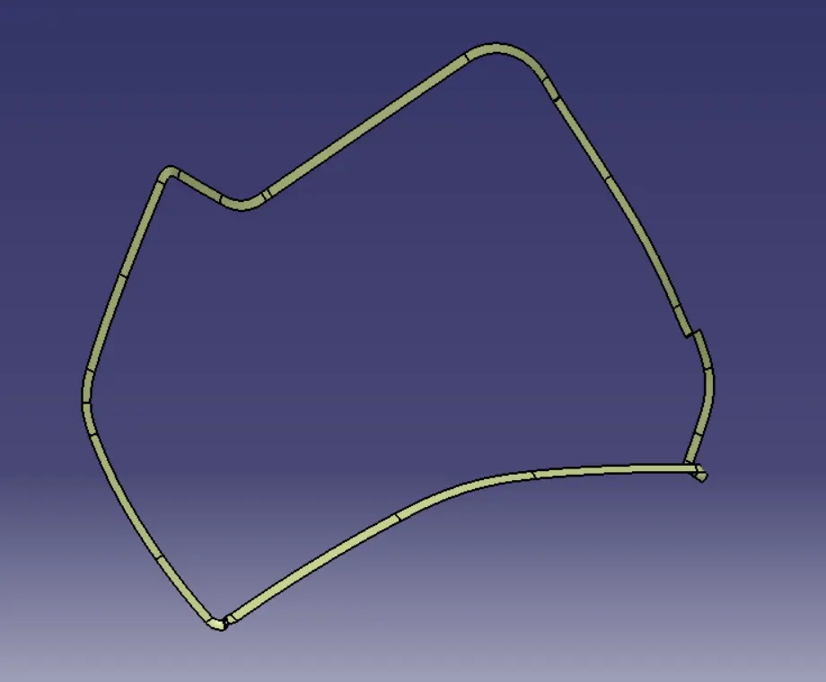
5)CREATION OF CLASS C SURFACE:
- The class C surface is the surface which is created to provide thickness to the class A surface with the help of class B surface.
- The class C surface is the middle portion of the class A and class B surfaces.
- The class C is created with the help of the sweep command in surface workbench.
- The class A surface's boundary is taken as profile (guide curve) and then tooling axis created is taken as direction of the sweep in subtype draft direction
- The draft angle for the sweep is 3 degrees.
- The holes are created using the same axis and draft angle.
- The attained sweep is joined with class A surface to obtain the class C surface.
- The final trim is obtained by trimming the class B with the class C surface.
- The final check to ensure the proper clossness of surface with the boundary command .
a)ARM REST:
b)LOWER SUBSTRATE:
c)MAP POCKET:
d)BOTTLE HOLDER:
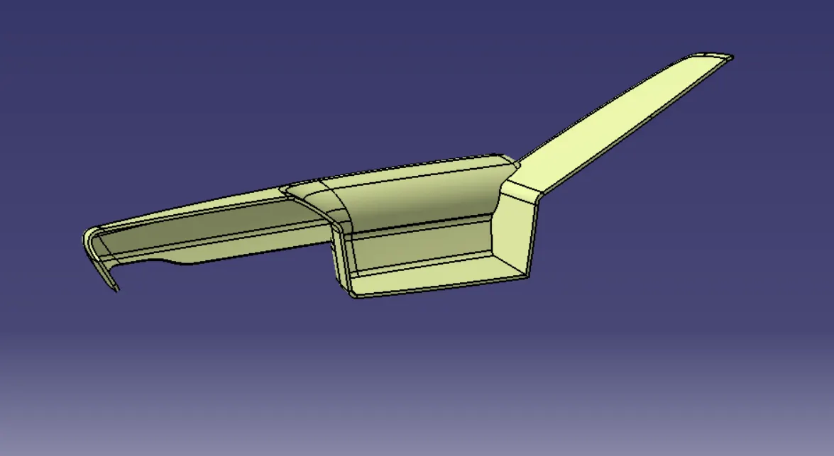
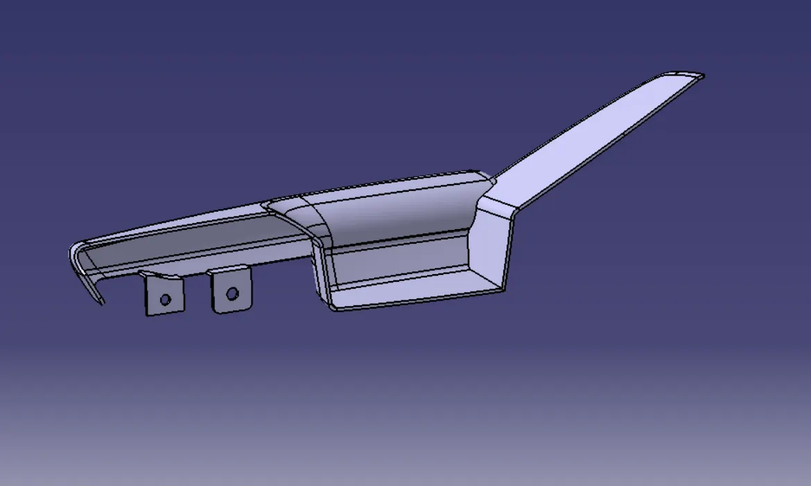
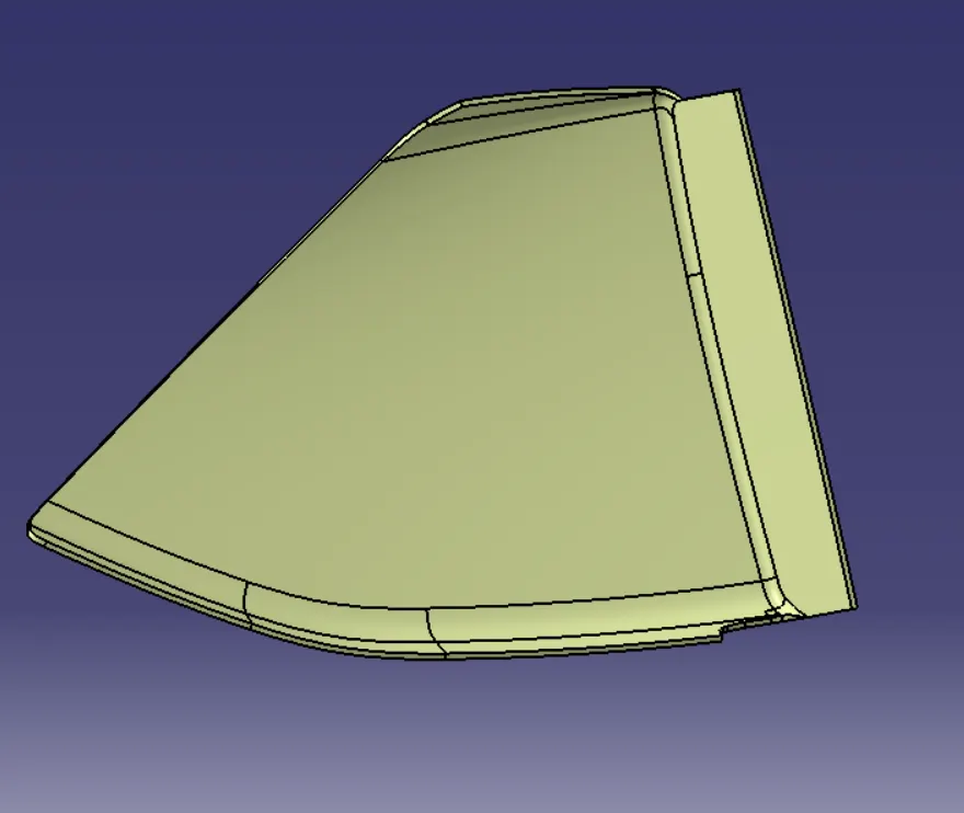
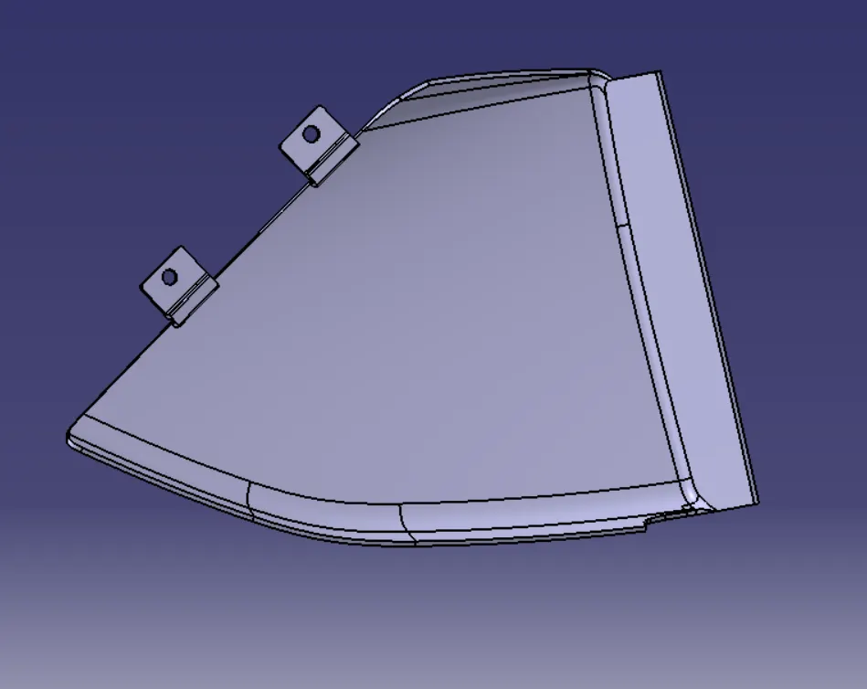
6) FINAL TRIM AND CLOSED BODY-
a)ARM REST:
b)LOWER SUBSTRATE:
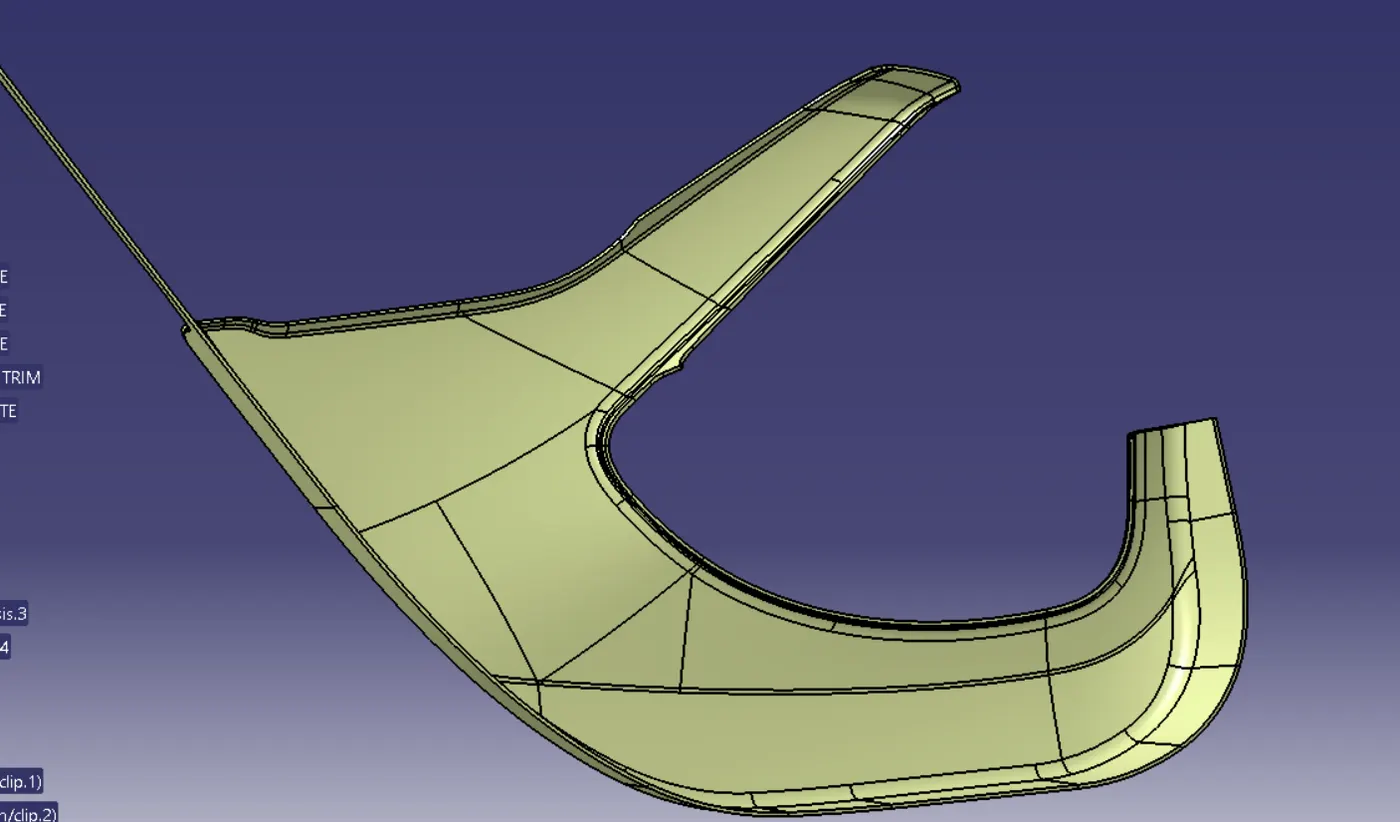
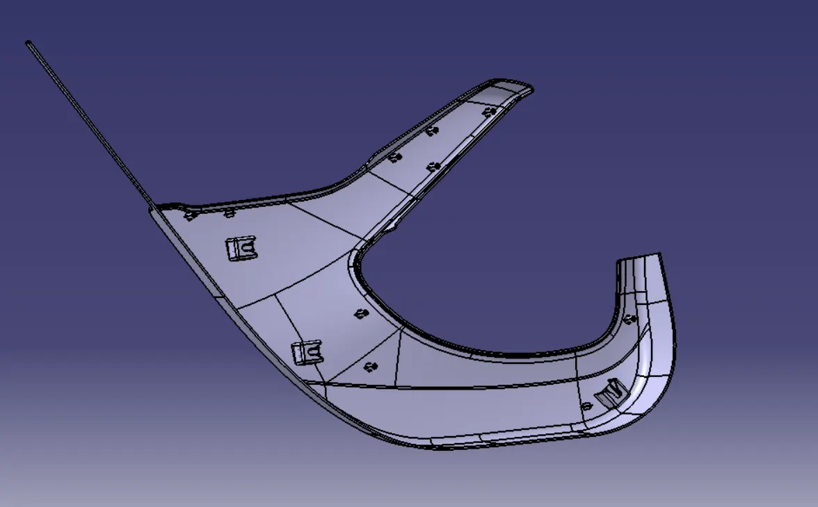
c)MAP POCKET:
d)BOTTLE HOLDER:
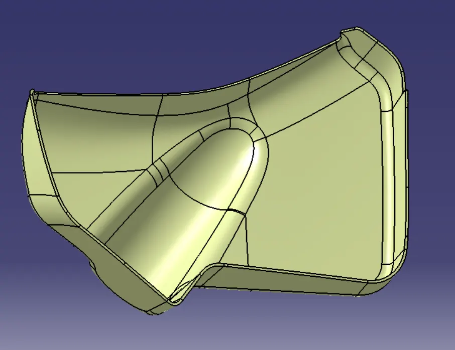
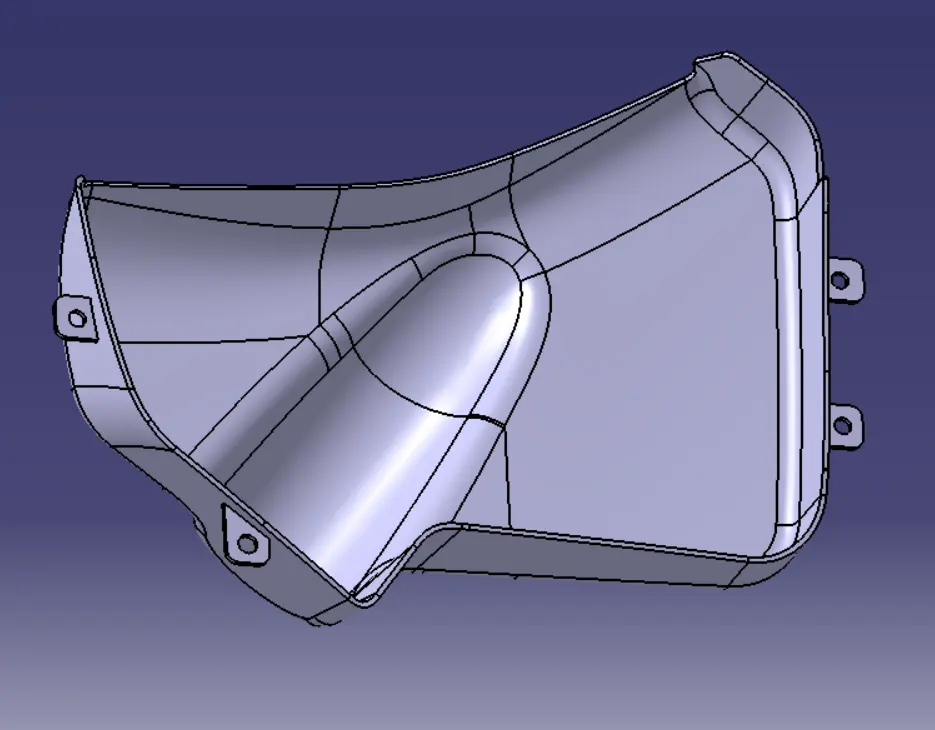
7) CREATING THE CLOSED BODY AND ASSIGNING IT AS MAIN BODY
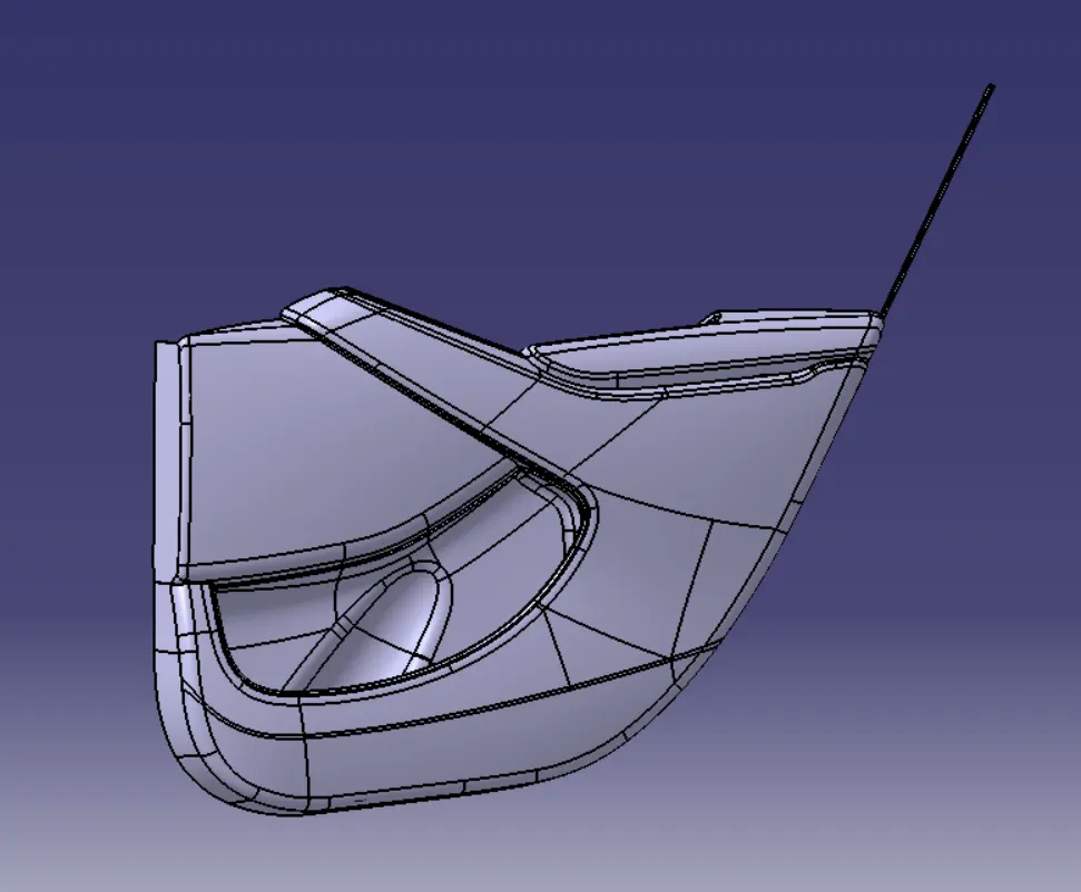
- Move to the part window and with the help of surface based feature close the surface to get the closed part body.
- Follow this for all the components.
8) CREATING THE ATTACHMENT FEATURES FOLLOWING THE MASTER SECTION.
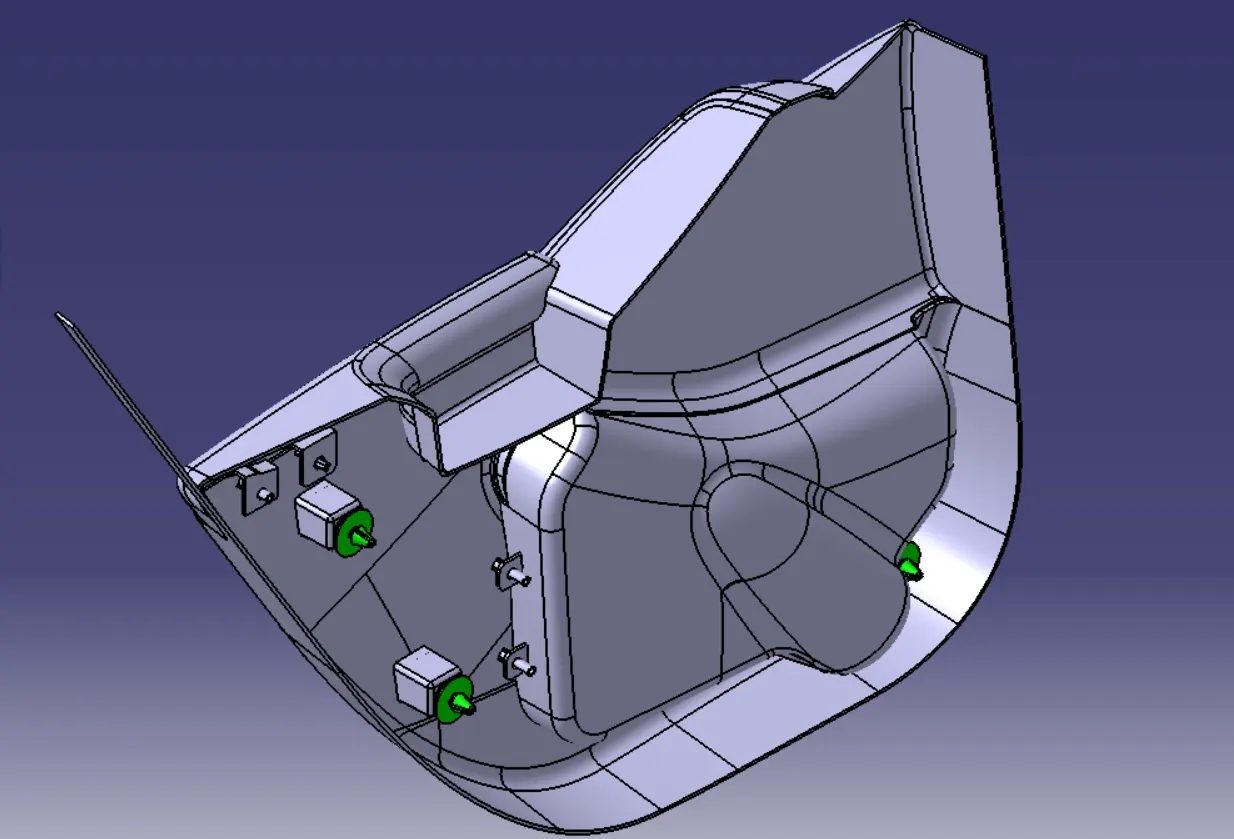
a) HEAT STAKES:
- Heat Staking is a pulsed-heat process to join two or more parts out of which one at least is made of plastic.
- The process is to deform the plastic material using heat and force at a set process time.
- The bond is made by partially de-forming the plastic part in order to fix the other.
- Heat Staking makes it easy to bond metal to plastic and is commonly used in high volume/low cost applications such as automotive, IT and consumer appliances.
- Similar and dissimilar materials may be joined: metal to metal, plastic to plastic, metal to plastic
- Accurate control operating within a small process window
- Local heating resulting in no damage to surrounding materials
- Processing of glass-filled materials
- No mechanical vibration
- Many heat-stake shapes possible through custom designed tools.
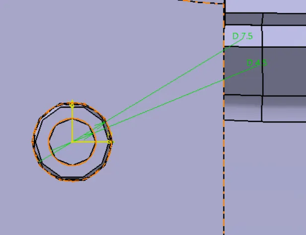
- As per Skill Lync Standards the below are the design standards likewise every OEM have their own standards
- Outer Diameter=7mm
- Inner Diameter= 5mm
- Draft for heat stake is 1.5deg
- Rib height = 6mm
- Heat Stake height is 6mm rib + thickness of flange of mating part + 12mm
b) RIBs:
- The ribs provide economical stiffness and strength to the part without increasing the overall thickness of the part.
- The ribs are used as locating and arresting in the assembly as locators.
- Proper allignment in mating parts, slot and rib pair is long lasting other than screw pair which loosen up with time.
- Acting as stops or guide for mating the tilted headlamps.
- Rib designs includes.
- thickness, quantity, height , manufacturibility and location.
- Ribs are thin, wall-like features typically designed into the geometry of a part to add internal support to walls or other features like bosses. In a similar fashion, gussets are support features that reinforce areas such as walls or bosses to the floor.
- Rib thickness at the base should be between 40% of the nominal wall thickness.
- Rib height should be 5 X the nominal wall thickness.
- Ribs should have 0.5 degrees of the draft (for ejection).
- Rib base radii should be 0.25 – 0.4 X the nominal wall thickness.
HERE WE HAVE USED THE LOWER SUBSTRATE FOR THE APPLICATION OF THE HEAT STAKES AND RIBS
c)DOG HOUSE:
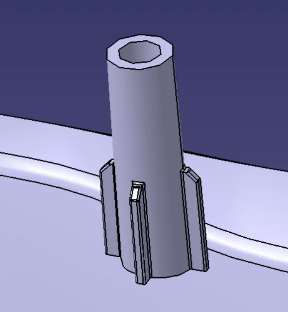
- Dog house is the attachment feature which helps you to assemble things at certain heights and also resolve the plastic defects.
- There are plenty dog house design which can be used for assembly purpose but we will be using the one provided to ous by the resources.
- The master section or the enginnering drawing must be followed for creating the dog house.
- In most cases the Dog house demands a separate tooling axis
- Tooling must be cleared for easy ejection of the component, from the core cavity. In order to clear tooling certain value of draft is given to the component.
- Minimum of 2-3deg is provided on all plastic components.
- All the Dog Houses created should be in the same direction.
d) LOCATORS:
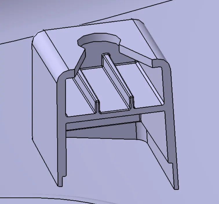
- Locators are used to locating the position of the mating part while assembling.
- The design rule for the locator is mostly the same as the rib but the height of the locator should be more than the heat stakes at a min of 5mm.
- The locator also constrains the movement of the mating part.
- The gap between Flange and the locator should range between 0.5mm and 1 mm.
- There are two types of locators.
1. 2-Way Locator.
2. 4-Way Locator.
e) PUSH PIN:
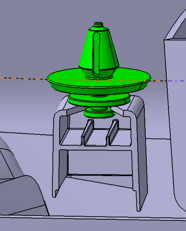
- The push pin is used as a Fixation Feature which locks with the BIW of the door panel.
- In our project the push pin is placed over the dog house.
f) FLANGES ON THE COMPONENT
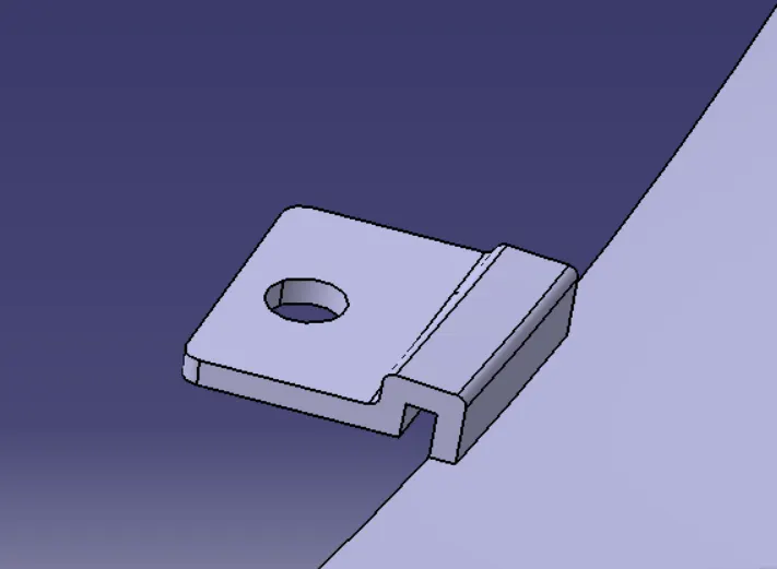
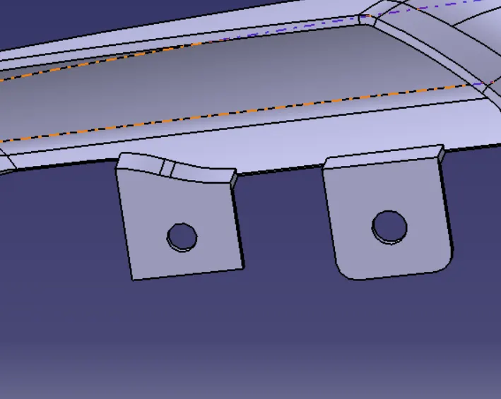
- These flanges will be build on the components for the fittment purpose with lower substrate.
- The hole at center will be guided along the heat stakes.
- Later top portion of the heat stake will be melted over it.
- The flange should rest on the supporting ribs on side .
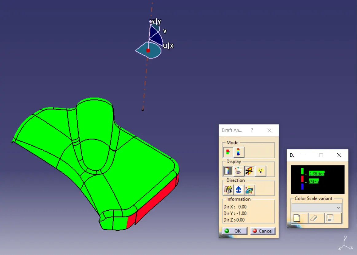
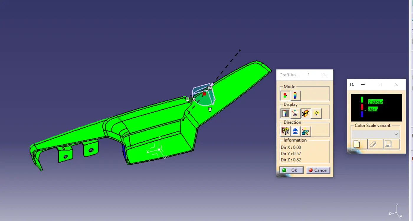
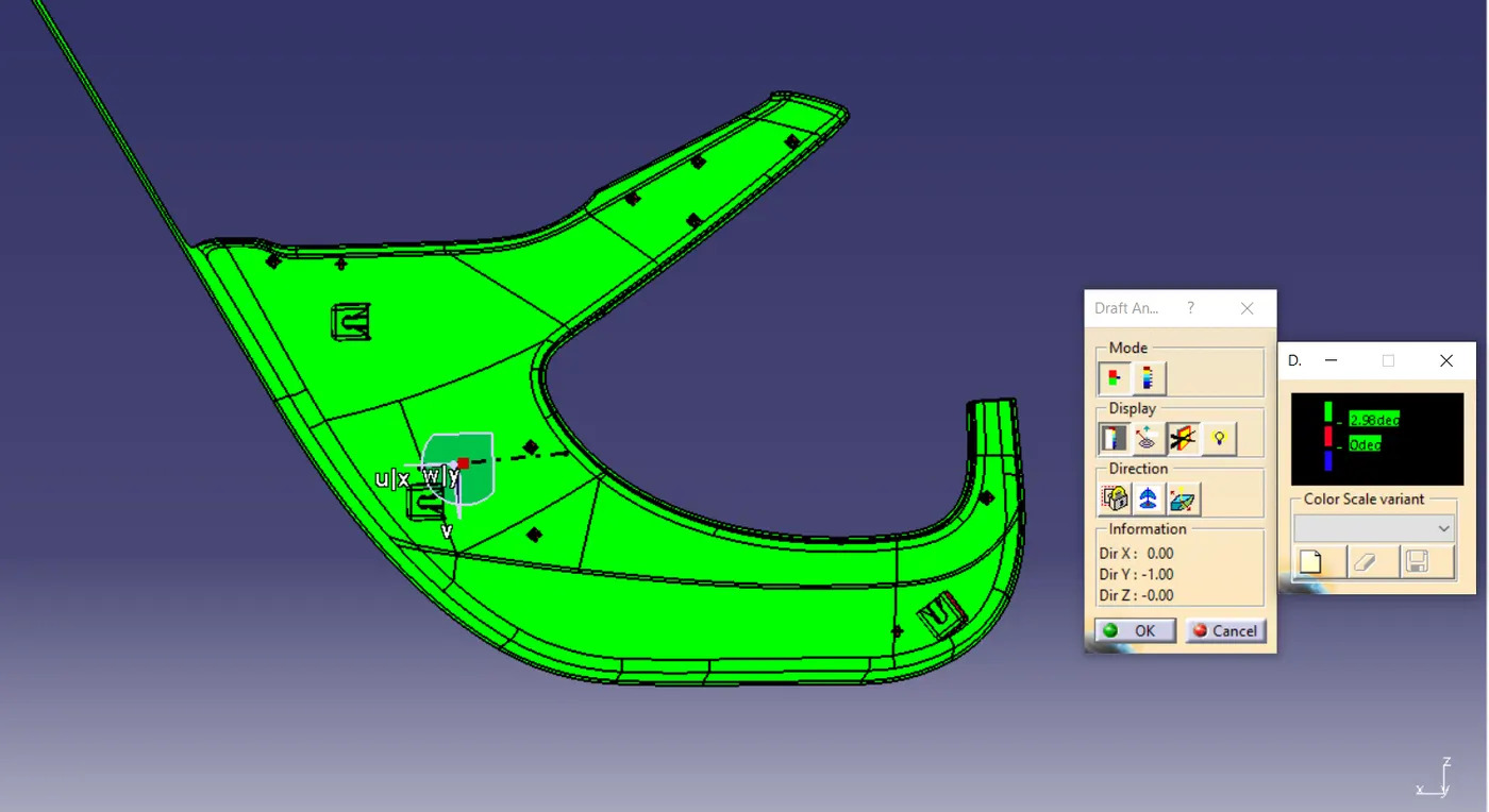
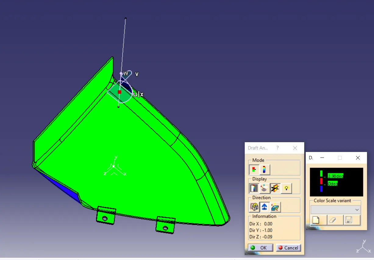
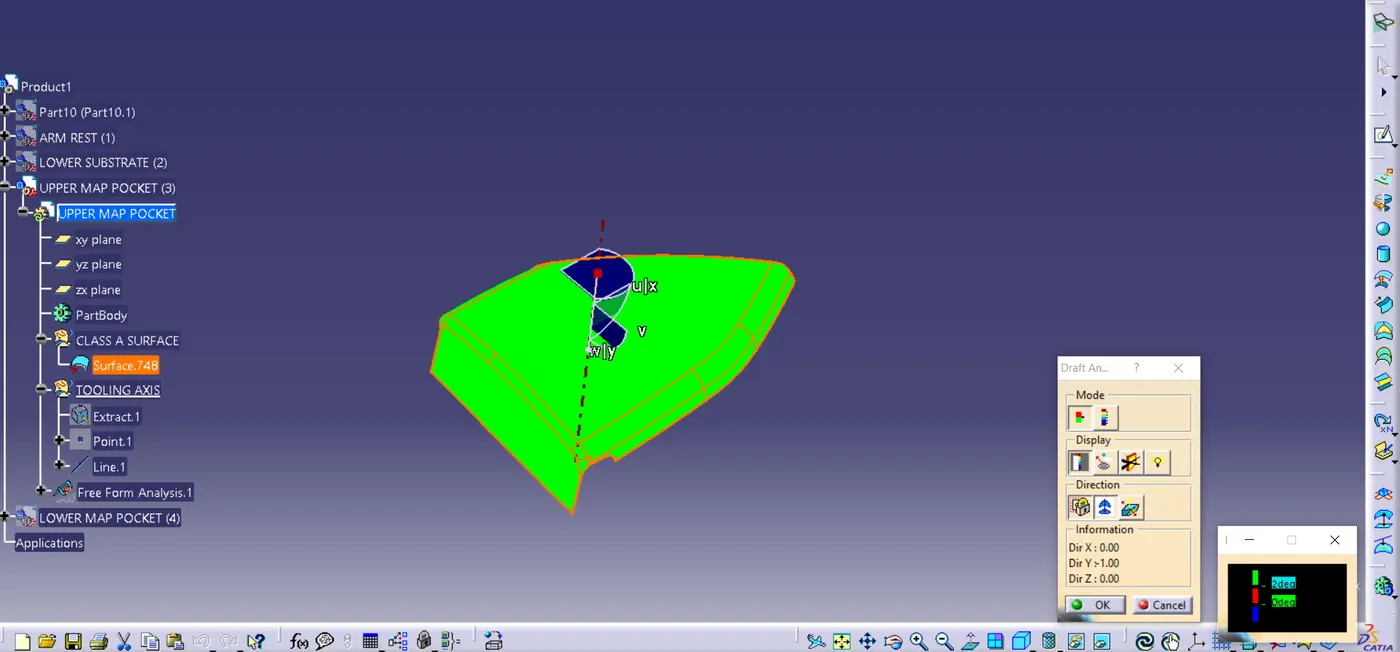
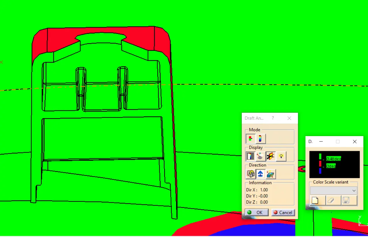
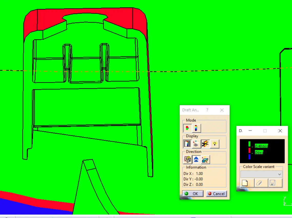
9)DRAFT ANALYSIS OF THE COMPONENTS:
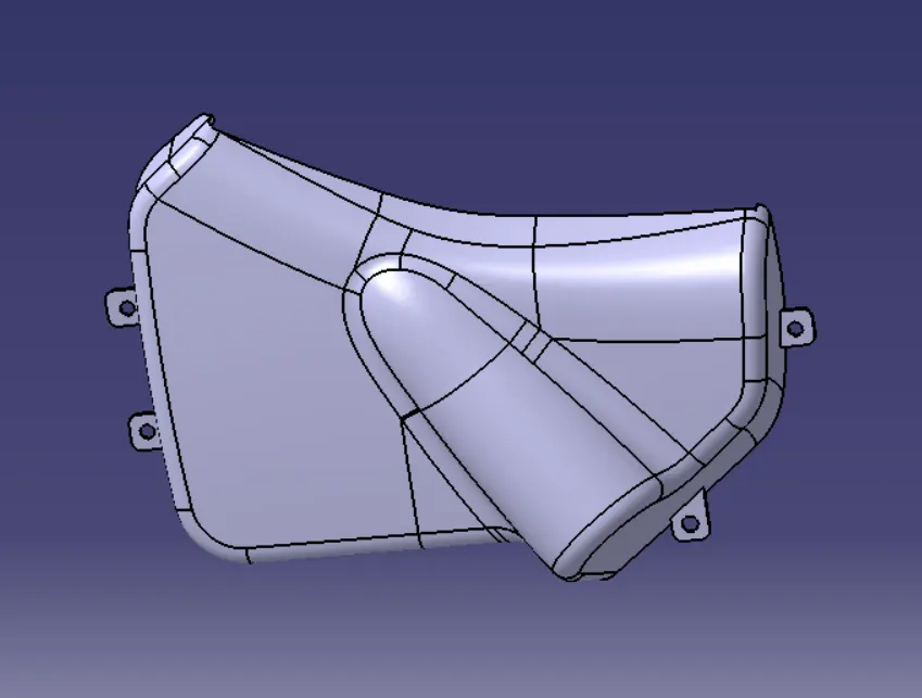
- The draft analysis is done to ensure that the draft in permeasible with the design consideration.
- The draft analysis is done by changing the visualization mode to customize and select shading as material.
- The draft based feature enables us to visualize and examine the draft.
- The draft window is has two tables one is for examining the draft and other one is the colour code.
- The draft value is set in the colour code window with each colour having their own significance.
- The red colour indicates the positive draft less than minimum draft where as the green colour indicates the minimum draft.
- The blue colour indicates the negative draft.
- For visualizing the draft the compass is aligned with the tool axis direction and the cursor is then made clicked upon the surface for viewing the draft.
- The quick view in display window enables to examine the draft value throughout the surface.
- Here both class A and closed body are given the minimum draft as 3 degrees.
- The attachment feature are given draft of 0.5 degrees.
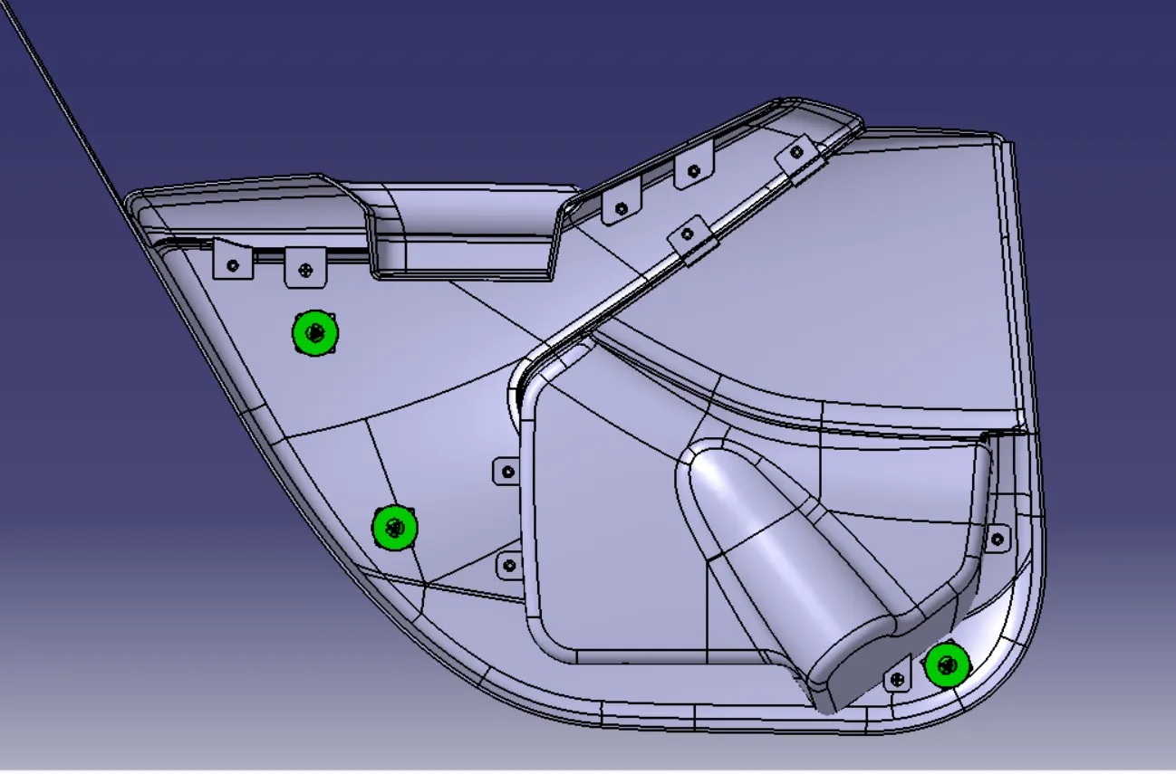
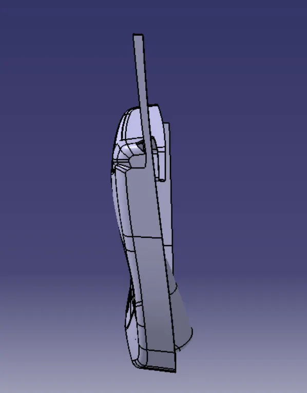
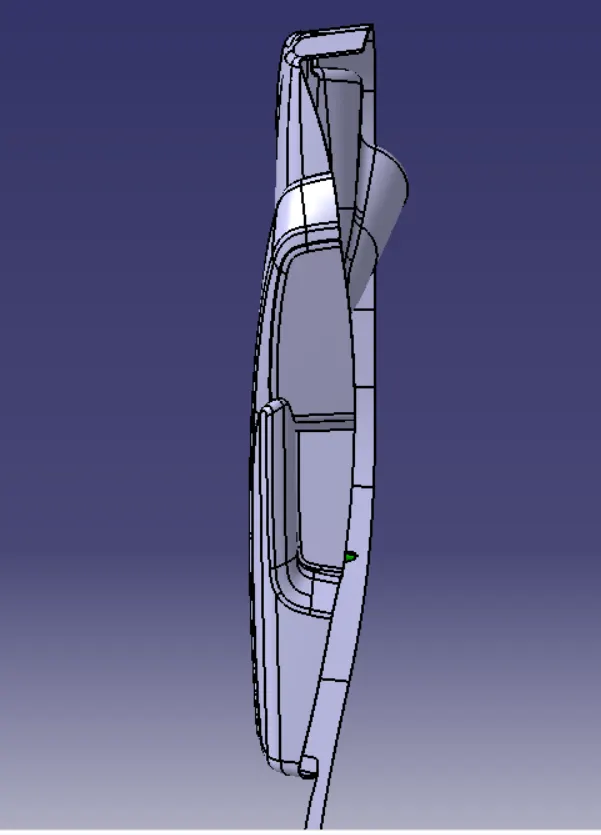
10) VIEWS:
ISOMETRIC VIEW:
SIDE VIEW:
FRONT VIEW:
TOP VIEW:
CONCLUSION:
- The Development of The Automotive Door Trim Panel from a Class A surface to a Closed Part Body with all the necessary attachment features by following all the design rules using CATIA V5 is done Successfully and all the required CATPart and CATProduct files are attached.