Project

Project #2:- solve an otto cycle and make plots for it.

Question

Write code that can solve an otto cycle and make plots for it.

Here are the requirements

  • Your code should create a PV diagram
  • You should output the thermal efficiency of the engine.

Basic of ideal otto cycle:-

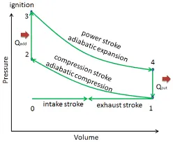
Otto cycle is used for SI engine. Its consist of four strokes and four processes. These four processes of an engine will be responsible for the four strokes. strokes are responsible for developing the power of power of engine that results in vehicle movement. The ideal otto cycle mainly consists for processes

  1. Iscentropic/Adiabatic compression(1-2)
  2. Contant volume heat addition(2-3)
  3. Iscentropic//Adiabatic expansion(3-4)
  4. Contant volume heat rejection(4-1)

fig1:- PV diagram of otto cycle

  • Compression Ratio:- Its ratio of volume of piston at BDC to volume of piston at TDC

compression ration(cr)=volume of piston at BDC/volume of piston at TDC

also

compression ration=swept volume+clearance volumn/clearnace volume

cr=s_v+c_v/c_v

also,

v1=piston at BDC=s_v+c_v

v2=piston at TDC=c_v

so, Compression ratio=v1/v2

  • Expansion Ratio:- its ratio of volume before expansion to volumn after expansion.

expansion ratio(er)=v3/v4

  • Swept volume(v_s):- Its volume of cylinder when piston is at BDC or volume of cylinder before compresion.
  • Clearance volume(v_c):- Its volume of cylinder when piston is at TDC or volume after compression.

Program 1:- Otto cycle using MATLAB(Only state points)
clear all
close all
clc
%PV Diagram for air standard otto cycle
%state variables
p1=101325 % 1atm pressure
t1=400% kelvin
t3=2500
gamma=1.4
%engine geometric parameters
%engine bore(d)
bore=0.1;
%compression ratio
cr=12;
% stroke length
stroke=0.1;
%connecting rod length
con_length=0.17;
%calculating swept volume and clearance volume
v_swept=pi/4*bore^2*stroke;
v_clearance=v_swept/(cr-1);
v1=v_swept+v_clearance
v2= v_clearance
% state variables at point2
% according to ideal gas law
% p1v1^gamma=p2v2^gamma
% p2=p1v1/v2^gamma
% where v1/v2=cr
% p2=p1*cr^gamma
p2=p1*cr^gamma;
%also, p1v1/t1=p2v2/t2
t2=p2*v2*t1/(p1*v1);
% state variables at point 3
% as it is contant volume heat additon process
v3=v2
% p3v3/t3=p2v2/t2
% p3= p2v2t3/v3t2
%p3= P2*t3/t2 where v2=v3
p3= p2*t3/t2;
% state variables at point 4
v4=v1
% as it is contant volume heat rejection process
% p3v3^gamma=p4v4^gamma
% p4=p3v3/v4 ^gamma
% p4=p3*(v3/v4)*gamma
p4=p3*(v3/v4)^gamma;
%plotting
figure
hold on
plot(v1,p1,'*','color','r')
plot(v2,p2,'*','color','r')
plot(v3,p3,'*','color','r')
plot(v4,p4,'*','color','r')
xlabel('volume(m3)');
ylabel('pressure(kg/m3)');
now,in above program
clear all- used to clear all text from commond window
close all- used to close files open in window
clc- used to clear command window
Input parameters are taken as per given in program.
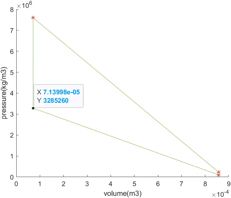
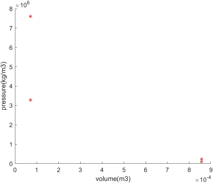
finally plot function is used to plot pv digram. after running all program we are getting state points at four different conditions.
Problem facing during this program-
while writing code for p4, i had written p4=p3*(v3/v4)*gamma; . Due to this mistake gamma getting multiflied with other values. i had use * instead of using ^.
fig2:PV diagram of otto cycle
Now, we have all state points of otto cycle. we have to join this but if we use plot function directly then its show straight line as a output. However in actual, there is no striaght line in iscentropic process. so, according coming output its error. Lets try to use plot function to join all state points in program 1 to check.
clear all
close all
clc
%PV Diagram for air standard otto cycle
%state variables
p1=101325 % 1atm pressure
t1=400% kelvin
t3=2500
gamma=1.4
%engine geometric parameters
%engine bore(d)
bore=0.1;
%compression ratio
cr=12;
% stroke length
stroke=0.1;
%connecting rod length
con_length=0.17;
%calculating swept volume and clearance volume
v_swept=pi/4*bore^2*stroke;
v_clearance=v_swept/(cr-1);
v1=v_swept+v_clearance
v2= v_clearance
% state variables at point2
% according to ideal gas law
% p1v1^gamma=p2v2^gamma
% p2=p1v1/v2^gamma
% where v1/v2=cr
% p2=p1*cr^gamma
p2=p1*cr^gamma;
%also, p1v1/t1=p2v2/t2
t2=p2*v2*t1/(p1*v1);
% state variables at point 3
% as it is contant volume heat additon process
v3=v2
% p3v3/t3=p2v2/t2
% p3= p2v2t3/v3t2
%p3= P2*t3/t2 where v2=v3
p3= p2*t3/t2;
% state variables at point 4
v4=v1
% as it is contant volume heat rejection process
% p3v3^gamma=p4v4^gamma
% p4=p3v3/v4 ^gamma
% p4=p3*(v3/v4)*gamma
p4=p3*(v3/v4)^gamma;
%plotting
figure
hold on
plot(v1,p1,'*','color','r')
plot(v2,p2,'*','color','r')
plot(v3,p3,'*','color','r')
plot(v4,p4,'*','color','r')
plot([v1 v2 v3 v4 v1],[p1 p2 p3 p4 p1])
xlabel('volume(m3)');
ylabel('pressure(kg/m3)');
after using this program we can get output as,

fig3: Error Due to use of plot command directly

Now, To correct this error we have to use thermodynamic relation during compression and expansion process.Also we have to determine how volumn is changes according to crank angle

Program 2- Code to create funtion

function [v]=engine_kinematics(bore,stroke,con_rod,cr,start_crank,end_crank)
a=stroke/2; %crank radius
R=con_rod/a; %length of connecting rod
%to calculate swept volumn and clearance volume
v_s=pi/4*bore^2*stroke
v_c=v_s/(cr-1)
%to calculate volumn changing according to piston position using fury's
%equation
%v/vc=1+1/2*(cr-1)*[R+1-cos theta-(R^2-cos theta^2)*1/2]
theta=linspace(start_crank,end_crank,100);
term1=0.5*(cr-1);
term2=R+1-cosd(theta);
term3=[R^2-sind(theta).^2].^0.5;
v=1+term1*(term2-term3)*v_c
end
In above coding,we have taken relation of v/vc=1+1/2*(cr-1)*[R+1-cos theta-(R^2-cos theta^2)*1/2] to calculate volume with respect to cranck angle inside a combusion chamber.
for our understanding and simplification we have divided above equation into three parts
1] term1=0.5*(cr-1)
2] term2=R+1-cosd(theta)
3] term3=[R*2-sind(theta).^2].^0.5
and finally combine this equation with
v=1+term1*(term2-term3)*v_c
Now, when we have to run this program, we have to call the function using function name engine_kinematics(bore,stroke,con_rod,cr,start_crank,end_crank). During this calling we have to write variables value and crack angle according to piston position.

During this calling or saving the code of function we have to take care of that function name and file name is same.

Problem-

My function is not running due to different file and function name during this coding. j have made it same to correct this error.

Now we have to calculate volume during compression and expansion process.

so for compression process,

To find volume,

v_compression=engine_kinematics(bore,stroke,con_rod,cr,start_crank,end_crank)

Now during compression piston is travelling from BDC to TDC.so,

v_compression=engine_kinematics(bore,stroke,con_rod,cr,180,0)

To find pressure,

p1*v1^gamma=c_contant

p_compression=c_contant/v_compression.^gamma

For expansion process,

To find volumn,

v_expansion=engine_kinematics(bore,stroke,con_rod,cr,start_crank,end_crank)

Now during expansion piston is travelling from TDC to BDC.so,

v_expansion=engine_kinematics(bore,stroke,con_rod,cr,0,180)

To find pressure,

p3*v3^gamma=c_contant

p_expansion=c_contant/v_expansion.^gamma

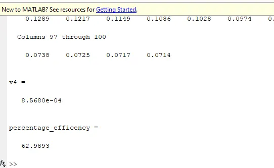
Thermal efficiecy can be calculated
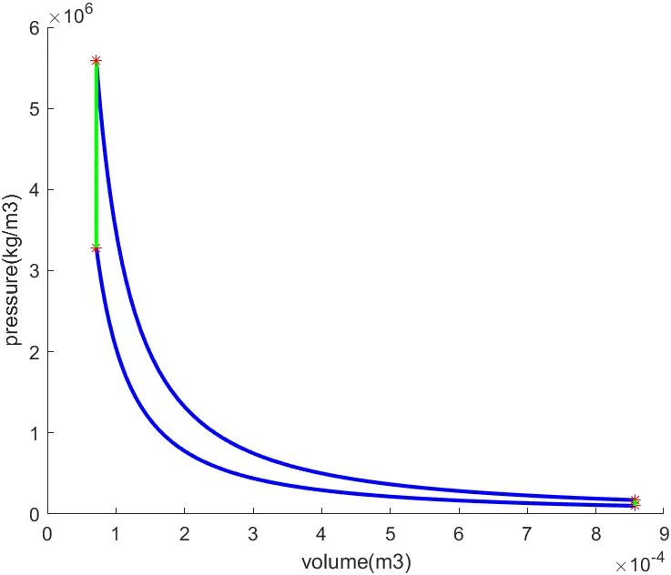
percentage_efficency=(1-(cr^(gamma-1))^-1)*100
Final Matlab Program:-
clear all
close all
clc
%PV Diagram for air standard otto cycle
%state variables
p1=101325 % 1atm pressure
t1=500 % kelvin
t3=2300
gamma=1.4
%engine geometric parameters
%engine bore(d)
bore=0.1;
%compression ratio
cr=12;
% stroke length
stroke=0.1;
%connecting rod length
con_rod=0.15;
%calculating swept volume and clearance volume
v_swept=(pi/4)*bore^2*stroke;
v_clearance=v_swept/(cr-1);
v1=v_swept+v_clearance
v2= v_clearance
% state variables at point2
% according to ideal gas law
% p1v1^gamma=p2v2^gamma
% p2=p1v1/v2^gamma
% where v1/v2=cr
% p2=p1*cr^gamma
p2=p1*cr^gamma;
%also, p1v1/t1=p2v2/t2
t2=p2*v2*t1/(p1*v1);
%to find pressure and volumn during compression
c_contant=p1*v1^gamma
V_compression=engine_kinematics(bore,stroke,con_rod,cr,180,0);
P_compression=c_contant./V_compression.^gamma;
% state variables at point 3
% as it is contant volume heat additon process
v3=v2
% p3v3/t3=p2v2/t2
% p3= p2v2t3/v3t2
%p3= P2*t3/t2 where v2=v3
p3= p2*t3/t2;
%To find pressure during expansion,
c_contant=p3*v3^gamma
V_expansion=engine_kinematics(bore,stroke,con_rod,cr,180,360);
P_expansion=c_contant./V_expansion.^gamma;
% state variables at point 4
v4=v1
% as it is contant volume heat rejection process
% p3v3^gamma=p4v4^gamma
% p4=p3v3/v4 ^gamma
% p4=p3*(v3/v4)^gamma
p4=p3*(v3/v4)^gamma;
%thermal efficiency
percentage_efficency=(1-(cr^(gamma-1))^-1)*100
%plotting
figure(1)
hold on
plot(V_expansion,P_expansion,'linewidth',2,'Color','b')
plot(V_compression,P_compression,'linewidth',2,'Color','b')
plot(v1,p1,'*','color','r')
plot(v2,p2,'*','color','r')
plot([v2 v3],[p2 p3],'linewidth',2,'Color','g')
plot(v3,p3,'*','color','r')
plot(v4,p4,'*','color','r')
plot([v4 v1],[p4 p1],'linewidth',2,'Color','g')
xlabel('volume(m3)');
ylabel('pressure(kg/m3)');
Problem while doing this program
I have mistakely mark ' term3=[R*2-sind(theta).^2].^0.5;' in function coding.Due to this error i am getting wrong graph.
Output Graph:

Fig3:- pv diagram of air standard cycle

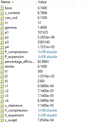
All variables value(output)
Thermal efficiency:-
Your portfolio, next

Ship work like this
in your own course.

Talk to a career counsellor

Free 20-minute call. We'll map the right course to where you want to work.

By submitting you agree to our Terms and Privacy Policy.

Talk to a career counsellor

Free 20-minute call. We'll map the right course to where you want to work.

By submitting you agree to our Terms and Privacy Policy.