Week 12- Final project
------------------------------------ AUTOMOTIVE DOOR INSIDE FEATURES ( FINAL PROJECT)----------------------------------
1. ALL COMPONENTS FEATURE TREE
- MASTER SECTION FEATURE TREE
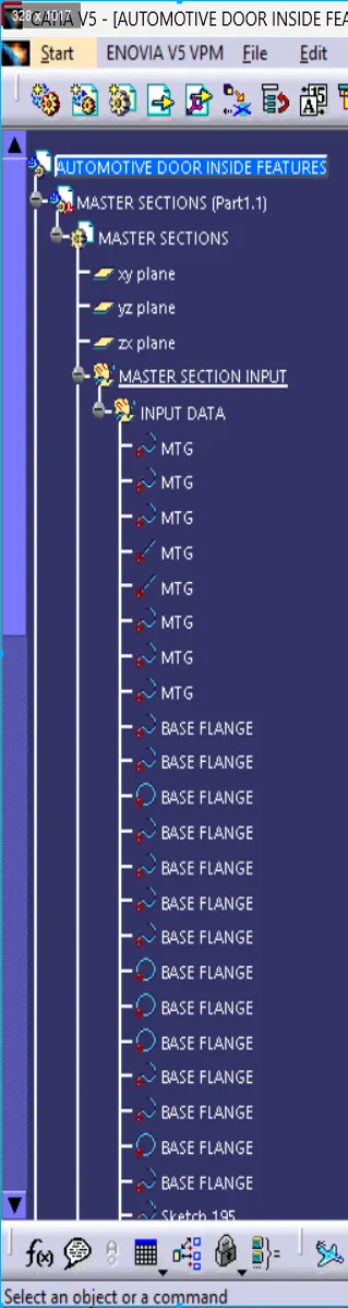
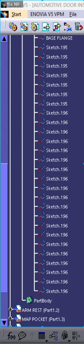
- ARMREST FEATURE TREE
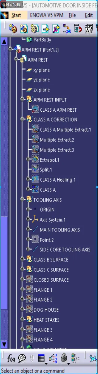
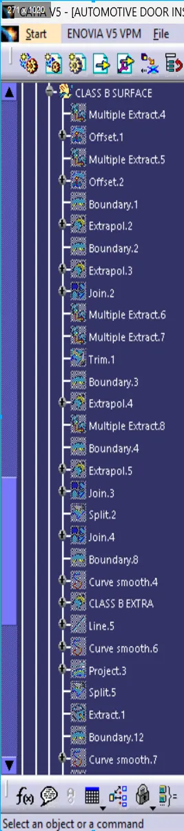
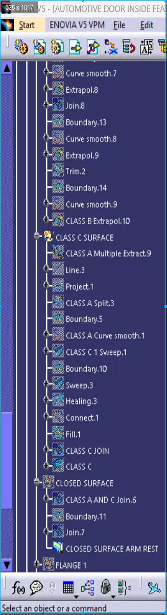
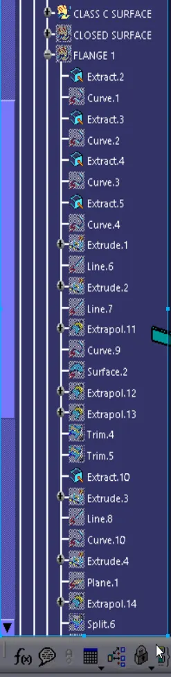
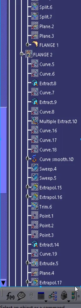
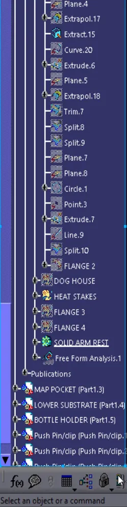
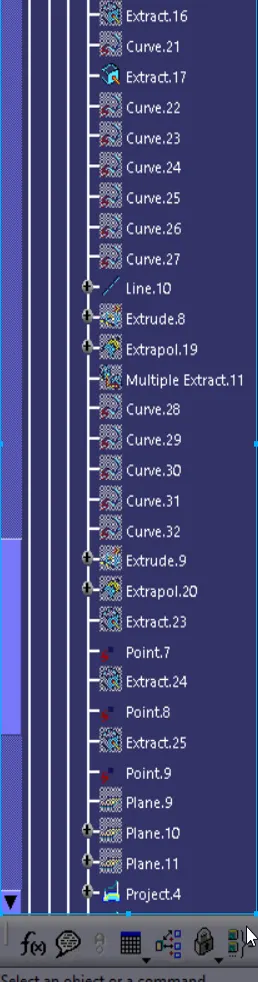
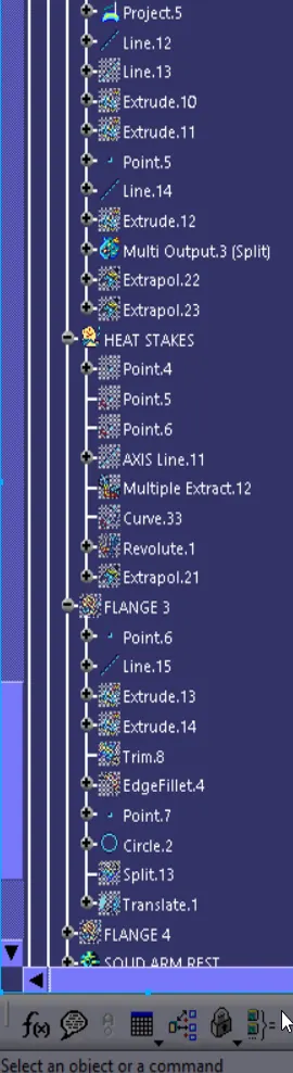
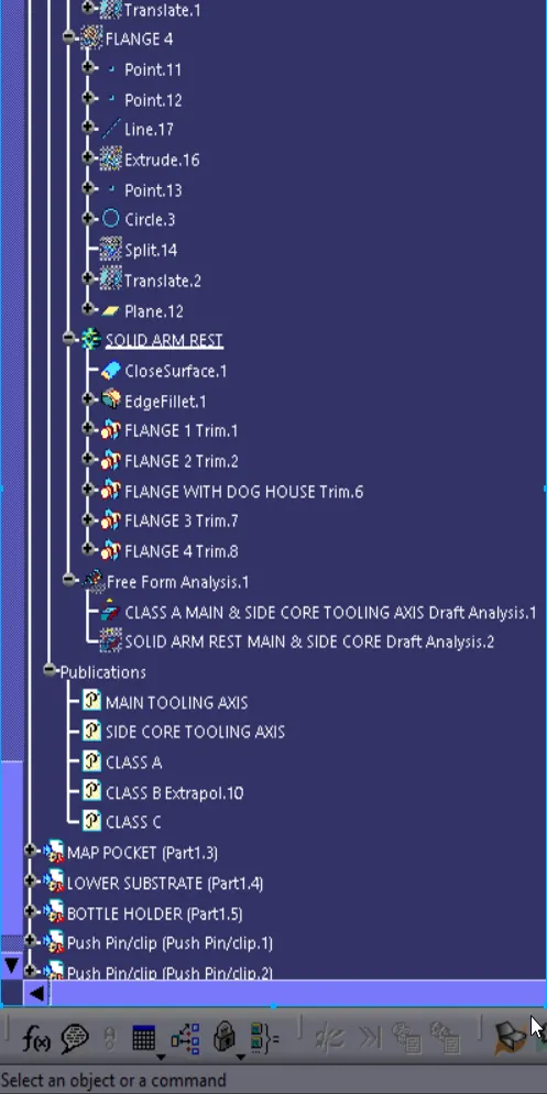
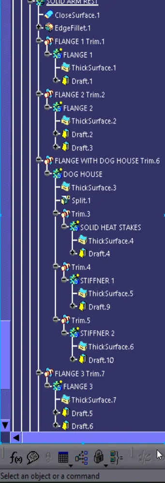
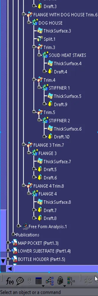
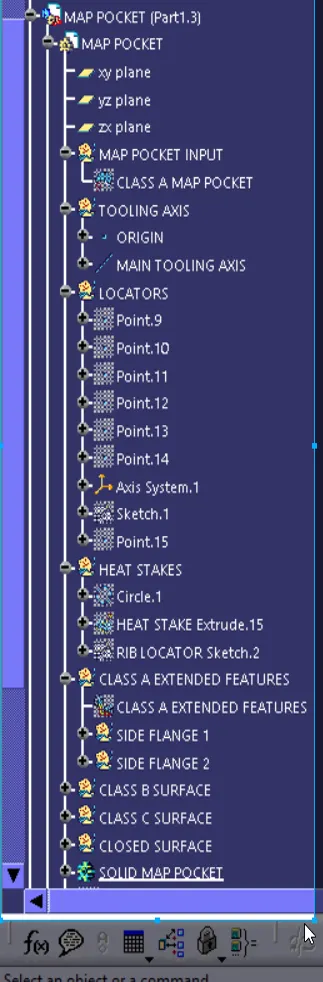
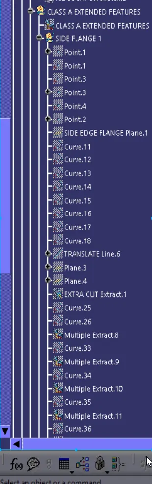
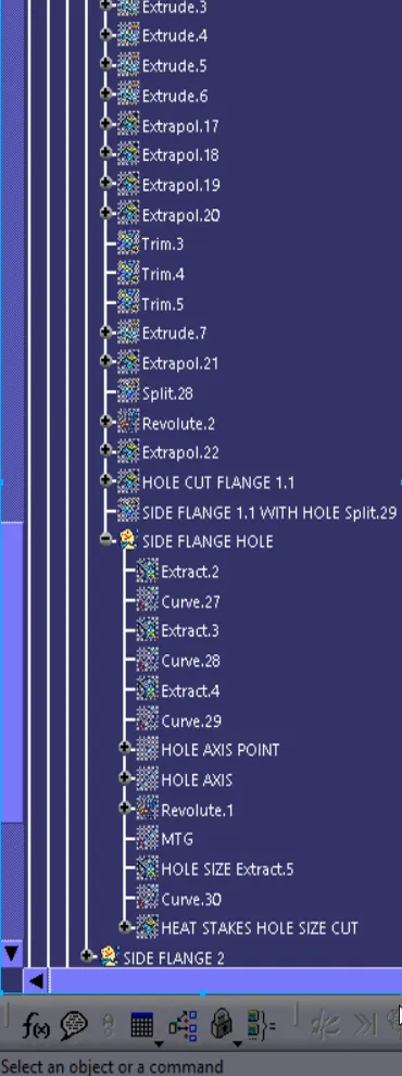
- MAP POCKET FEATURE TREE
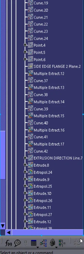
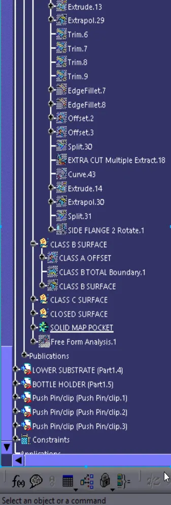
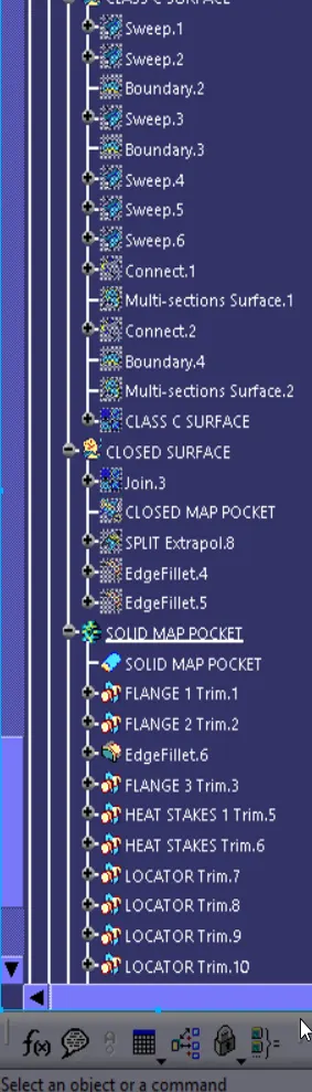
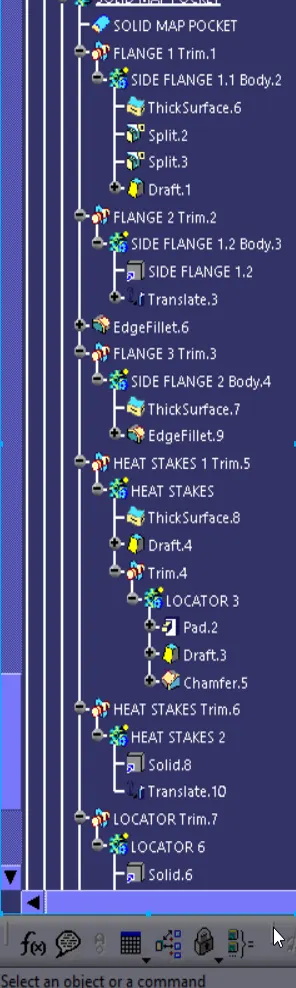
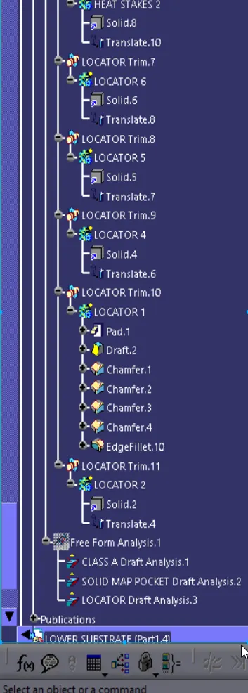
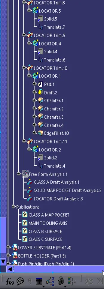
- LOWER SUBSTRATE FEATURE TREE
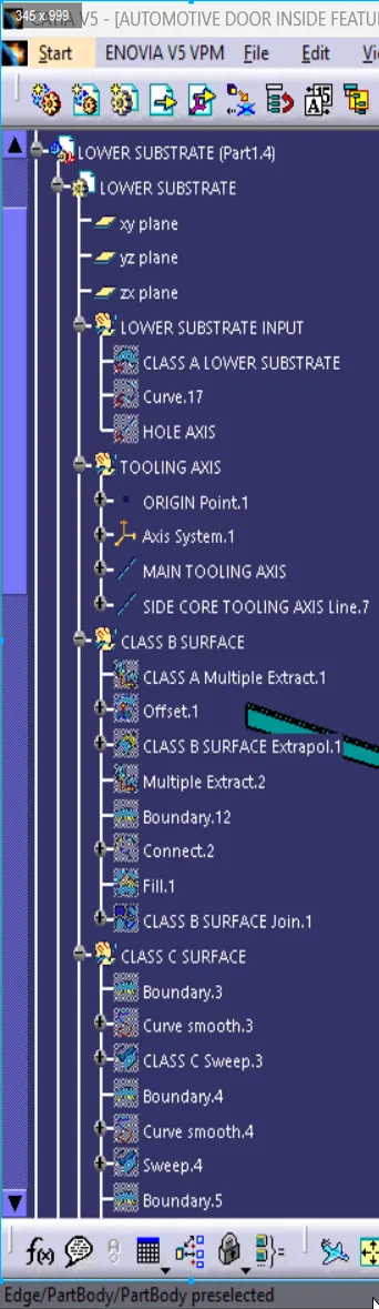
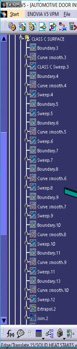
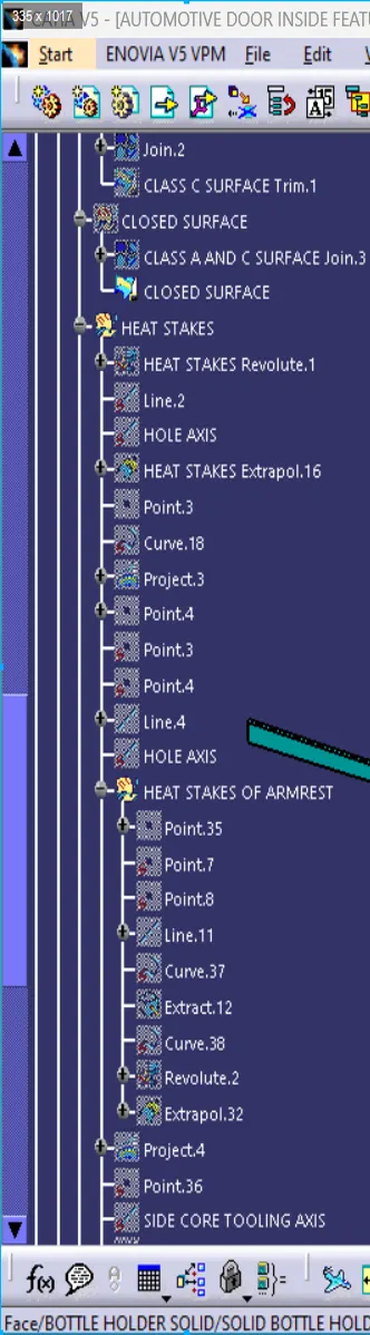
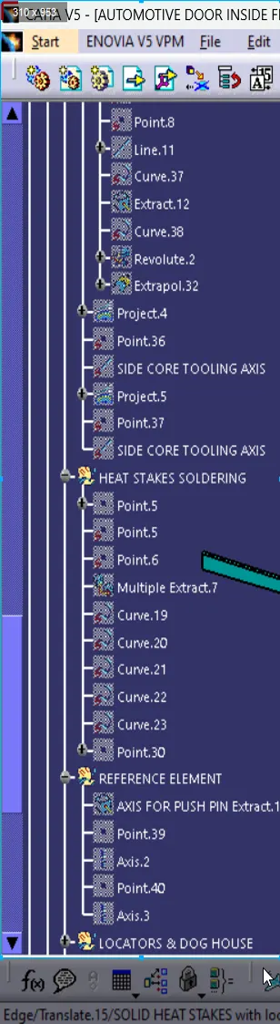
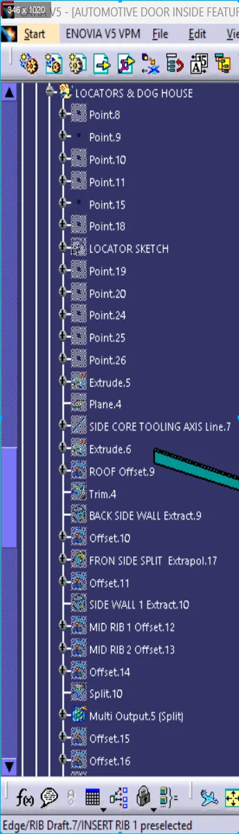
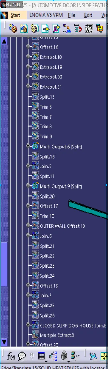
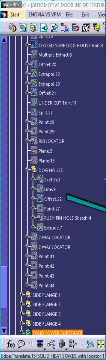
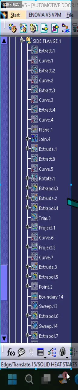
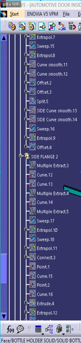
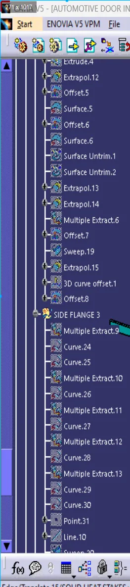
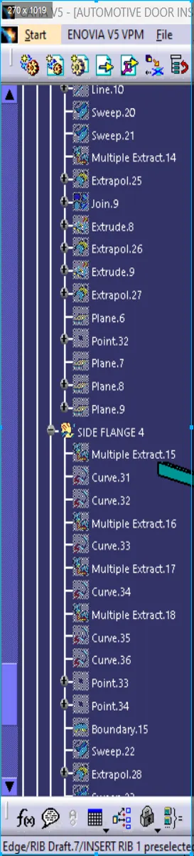
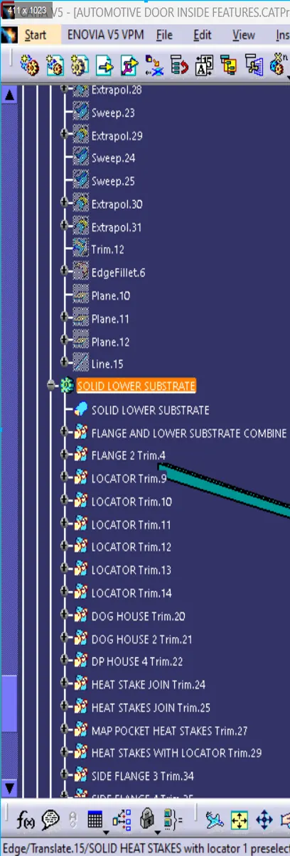
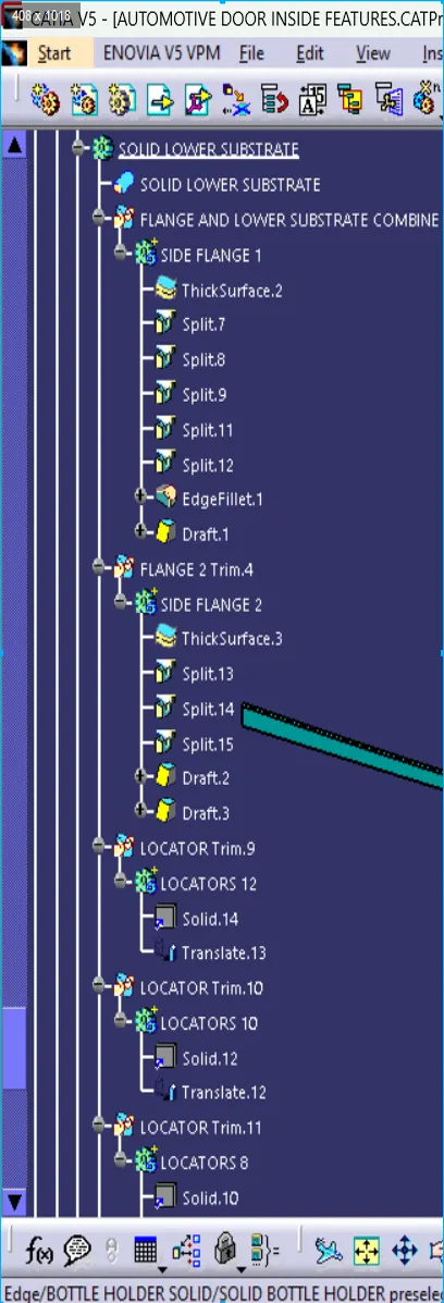
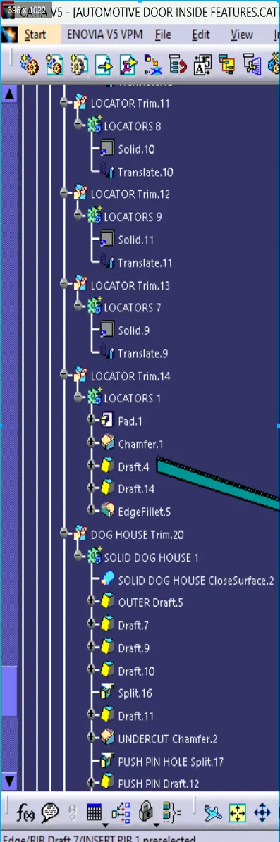
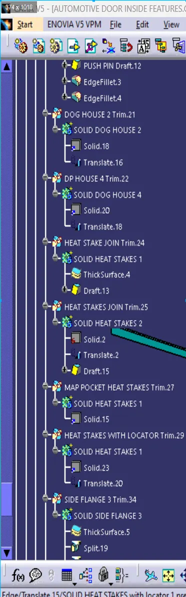
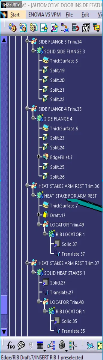
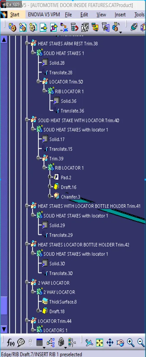
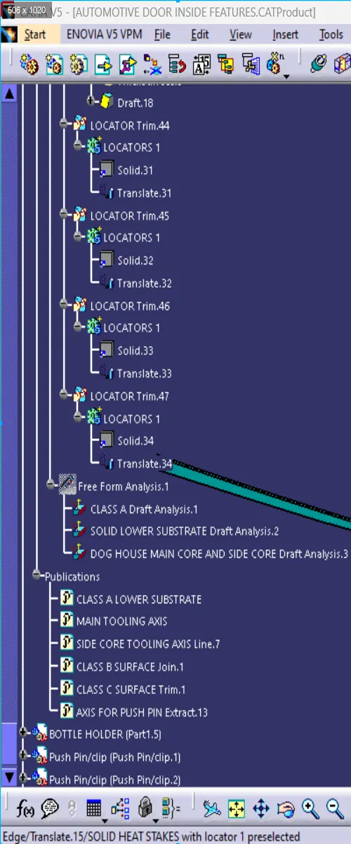
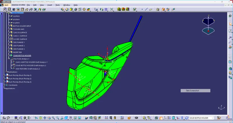
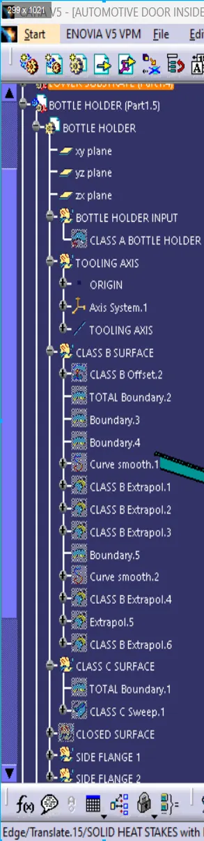
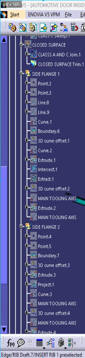
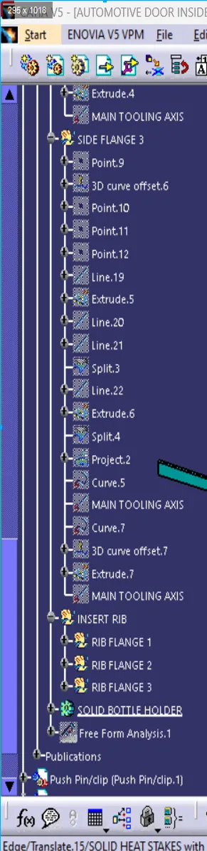
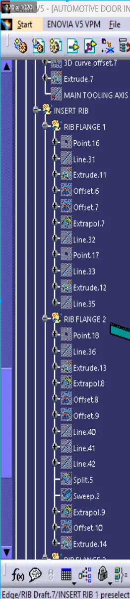
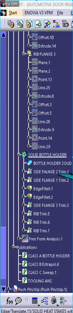
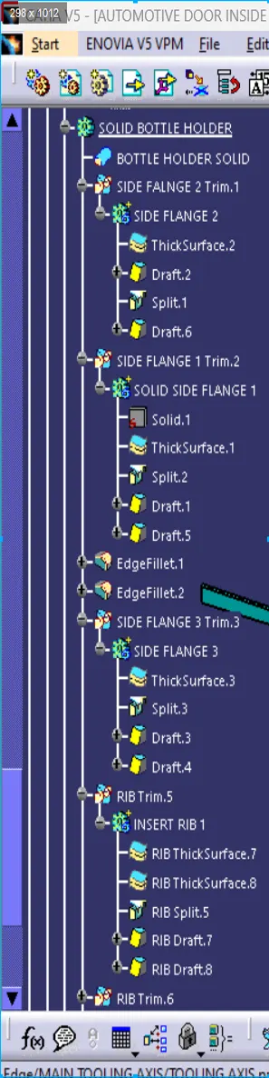
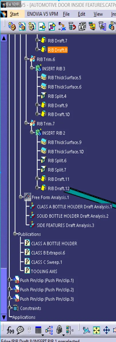
- BOTTLE HOLDER FEATURE TREE
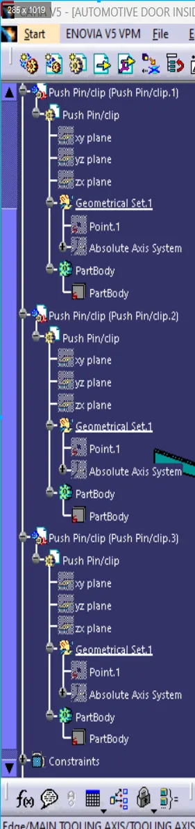
- PUSH PIN ASSEMBLY
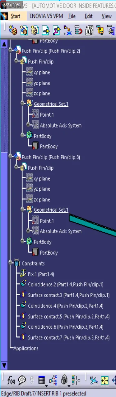
MASTER SECTION
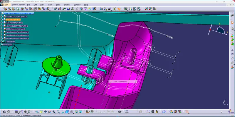
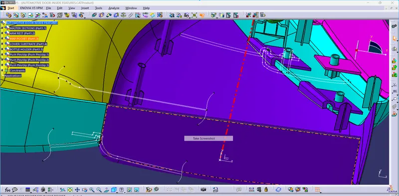
2. ALL COMPONENTS DRAFT ANALYSIS
- ARM REST DRAFT ANALYSIS OF CLASS A SURFACE AND SOLID BODY WITH ADDITIONAL ENGINEERING FEATURES
- MAIN CORE TOOLING AXIS DRAFT ANALYSIS W.R.T 2.9 deg DRAFT ANGLE
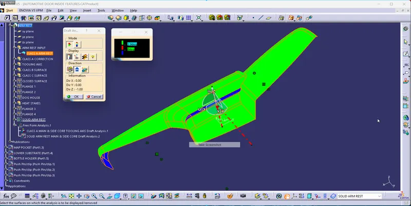
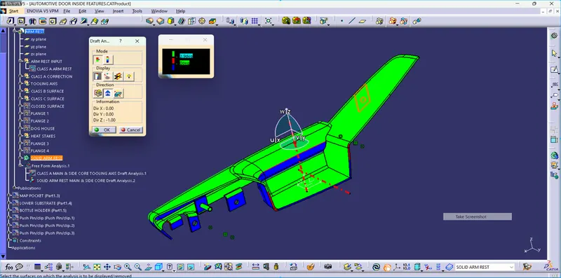
- SIDE CORE TOOLING AXIS DRAFT ANALYSIS W.R.T 2.9 deg DRAFT ANGLE
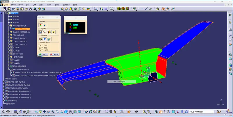
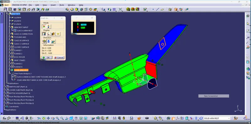
- HEAT STAKES WITH DOG HOUSE AND FLANGES DRAFT ANALYSIS W.R.T 0.49 deg DRAFT ANGLE
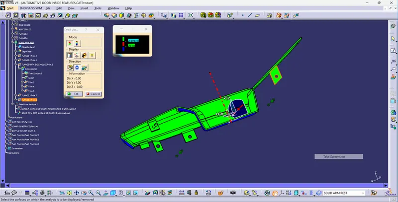
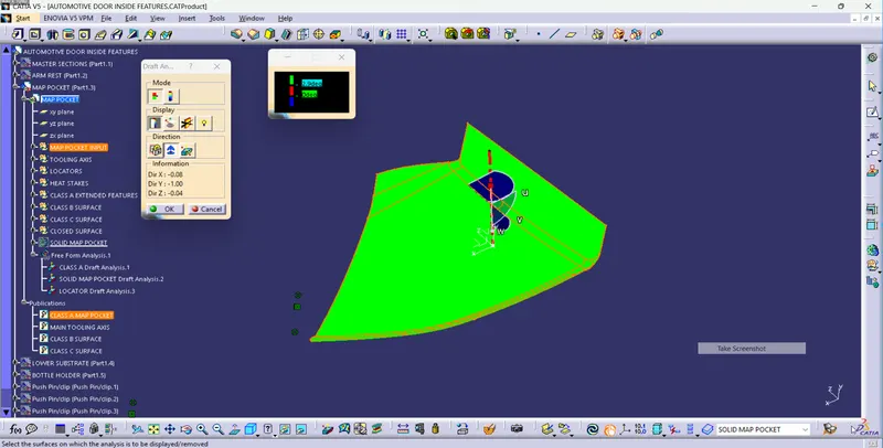
- MAP POCKET DRAFT ANALYSIS OF CLASS A SURFACE AND SOLID BODY WITH ADDITIONAL ENGINEERING FEATURES
- MAIN CORE TOOLING AXIS DRAFT ANALYSIS W.R.T 2.9 deg DRAFT ANGLE
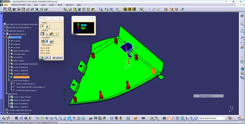
- HEAT STAKES WITH LOCATORS AND FLANGES DRAFT ANALYSIS W.R.T 0.49 deg DRAFT ANGLE
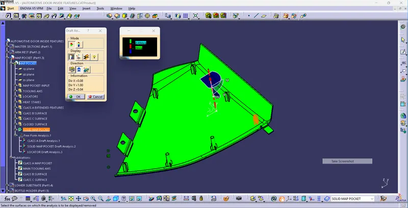
- LOWER SUBSTRATE DRAFT ANALYSIS OF CLASS A SURFACE AND SOLID BODY WITH ADDITIONAL ENGINEERING FEATURES
- MAIN CORE TOOLING AXIS DRAFT ANALYSIS W.R.T 2.9 deg DRAFT ANGLE
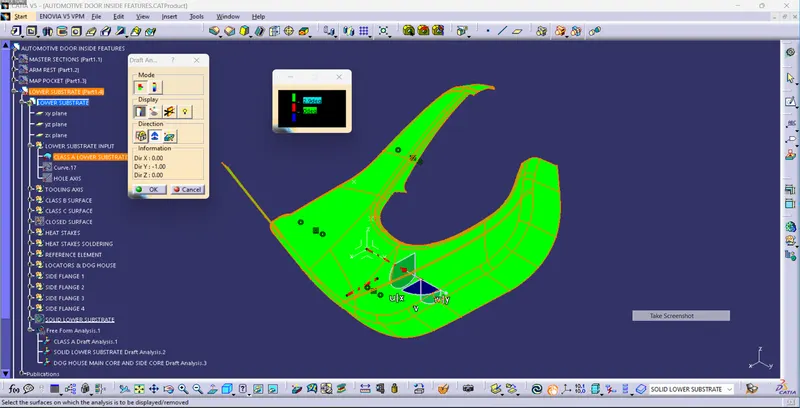
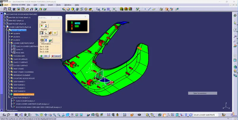
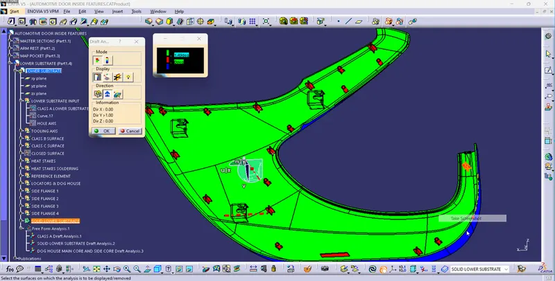
- HEAT STAKES WITH LOCATORS, FLANGES AND DOG HOUSE DRAFT ANALYSIS W.R.T MAIN CORE AND SIDE CORE TOOLING AXIS AND 0.49 deg DRAFT ANGLE
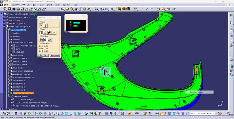
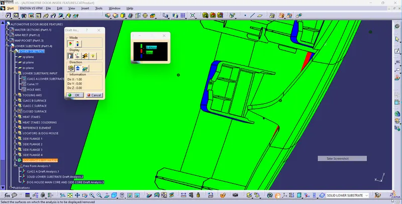
- DOG HOUSE DRAFT ANALYSIS W.R.T MAIN CORE TOOLING AXIS 1.49 deg
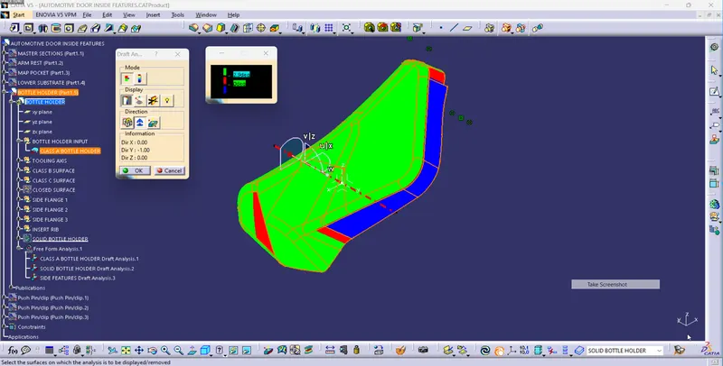
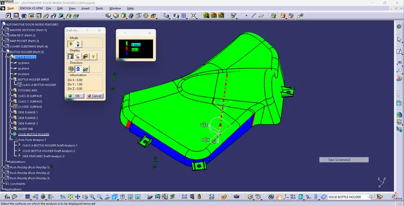
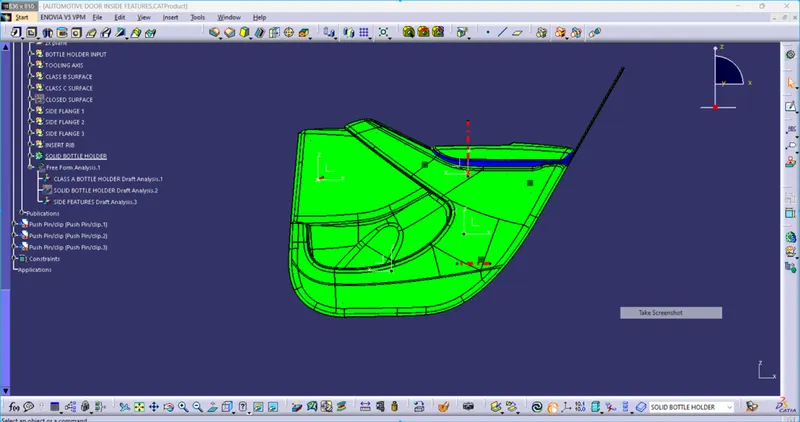
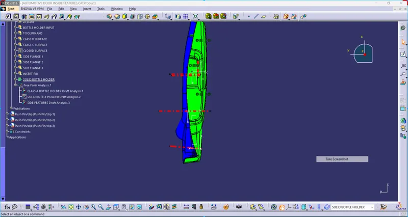
- BOTTLE HOLDER DRAFT ANALYSIS OF CLASS A SURFACE AND SOLID BODY WITH ADDITIONAL ENGINEERING FEATURES
- MAIN CORE TOOLING AXIS DRAFT ANALYSIS W.R.T 2.9 deg DRAFT ANGLE
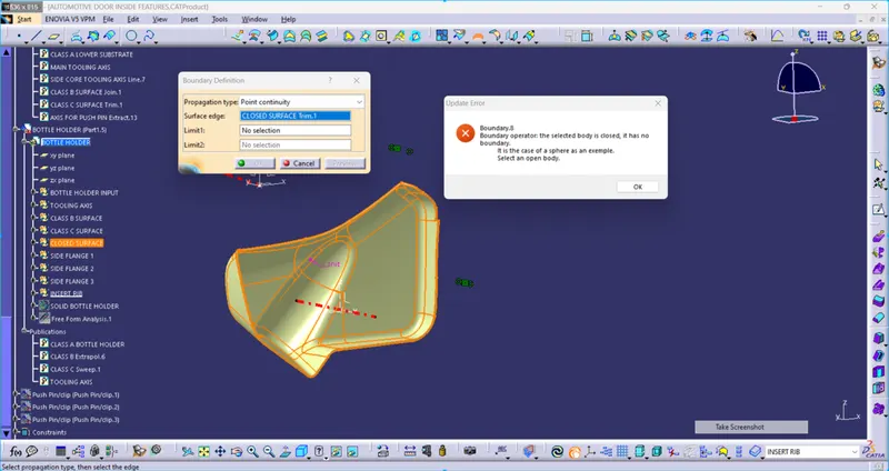
NOTE: CLASS A SURFACE DEFECT - The main source file is included the defected class A surface of BOTTLE HOLDER. I am trying to make the tooling direction of the bottle holder then the bottle holder shows the intersection area which is blue and this is not improving with different methods of tooling axis creation. so the final part will also be defective.
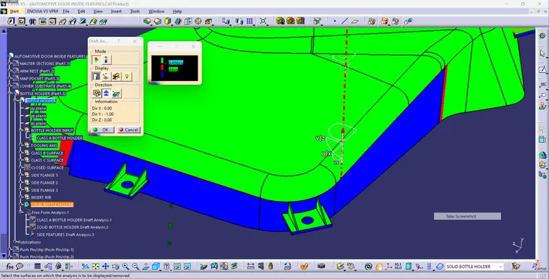
- FLANGES WITH STIFFNER DRAFT ANALYSIS W.R.T 0.49 deg DRAFT ANGLE
3. CLASS B & CLASS C SURFACE AND CLOSE SURFACES FOR ALL COMPONENTS
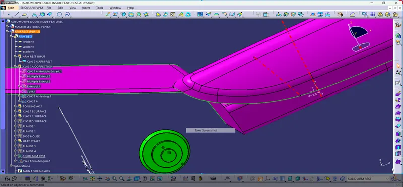
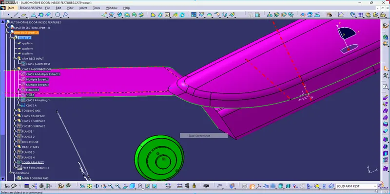
- CLASS B AND CLASS C SURFACE ARMREST
NOTE: The class A surface of the Armrest was not correct so I repaired the given class A then I created the class B surface.
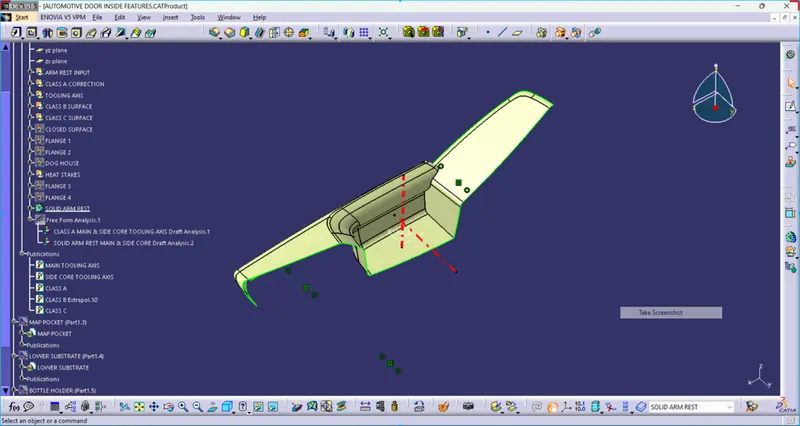
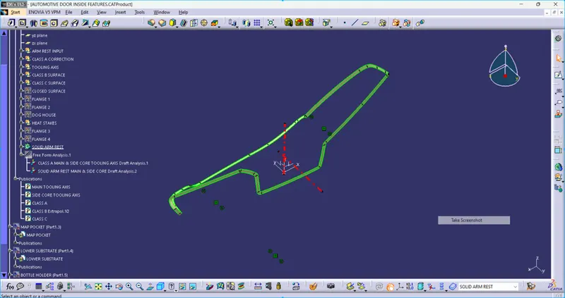
Class B is created by offsetting Improved Class A by 2.5 mm as per the master section.
- CLASS B AND CLASS C SURFACE MAP POCKET
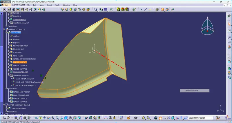
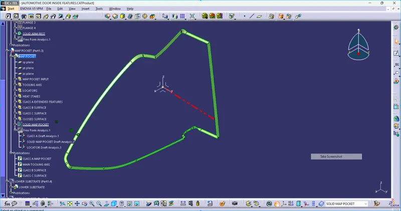
Class B is created by offsetting Improved Class A by 2.5 mm as per the master section.
- CLASS B AND CLASS C SURFACE LOWER SUBSTRATE
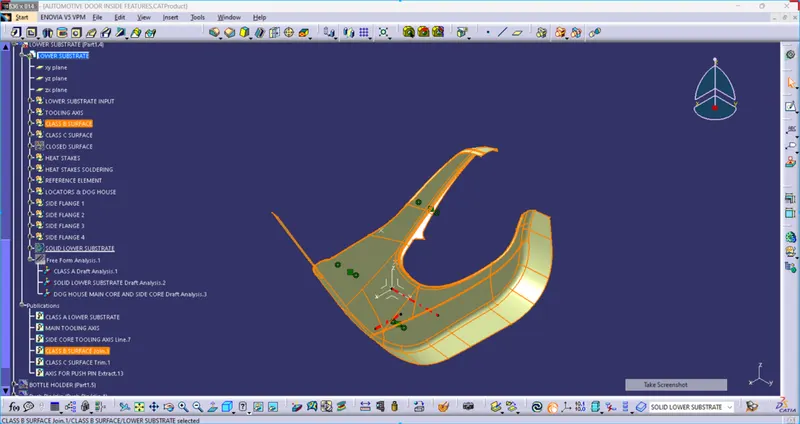
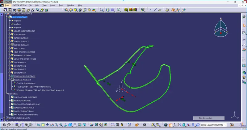
Class B is created by offsetting Improved Class A by 2.5 mm as per the master section.
- CLASS B AND CLASS C SURFACE BOTTLE HOLDER
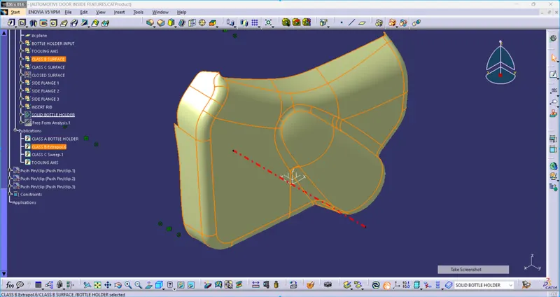
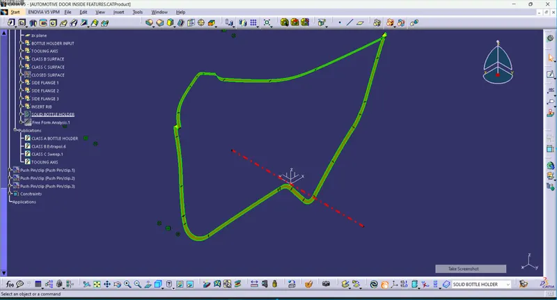
Class B is created by offsetting Improved Class A by 2.5 mm as per the master section.
- CLOSE SURFACES FOR ALL COMPONENTS
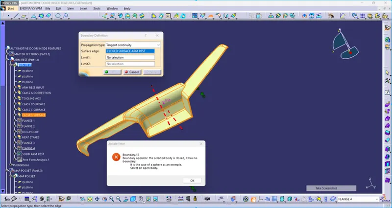
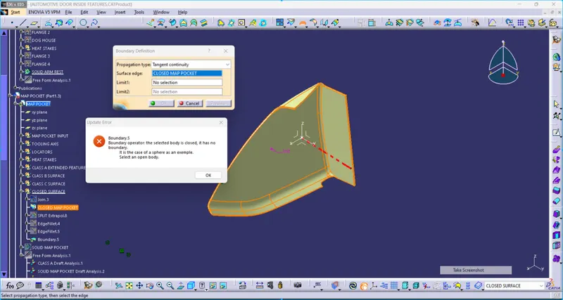
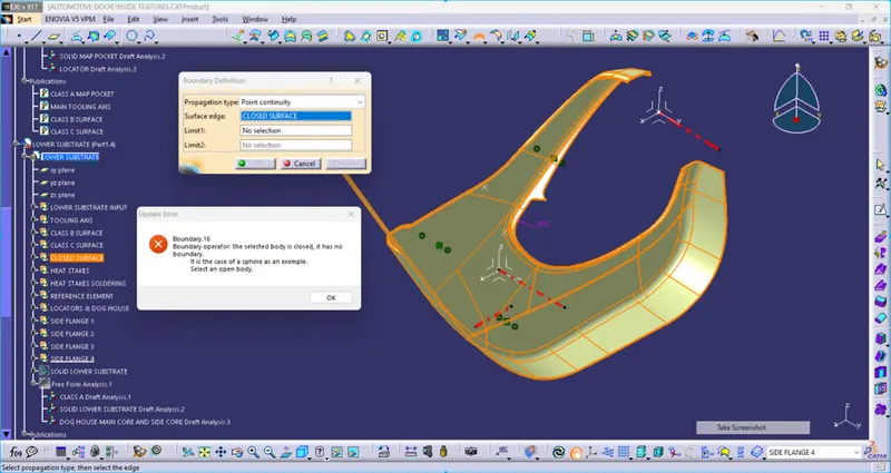
4. TOOLING AXIS CREATION FOR ALL COMPONENTS
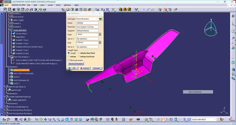
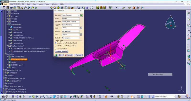
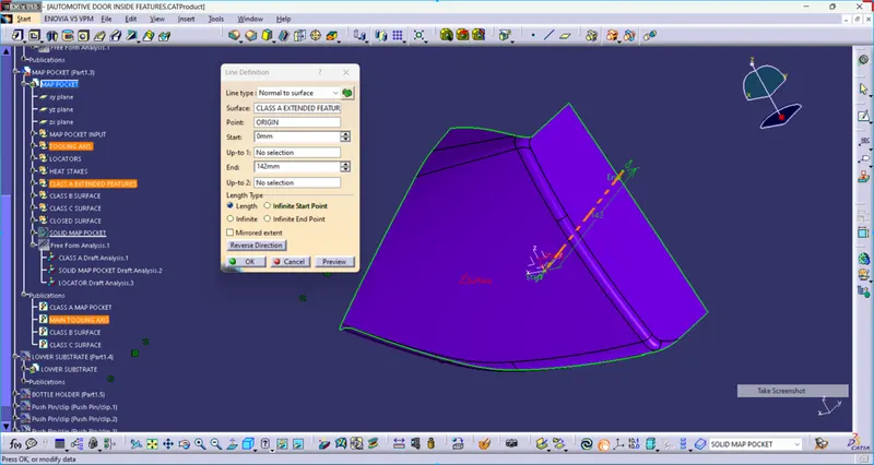
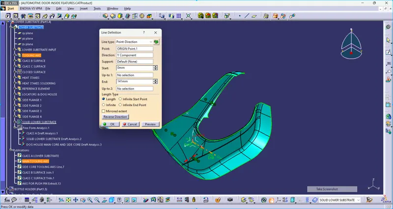
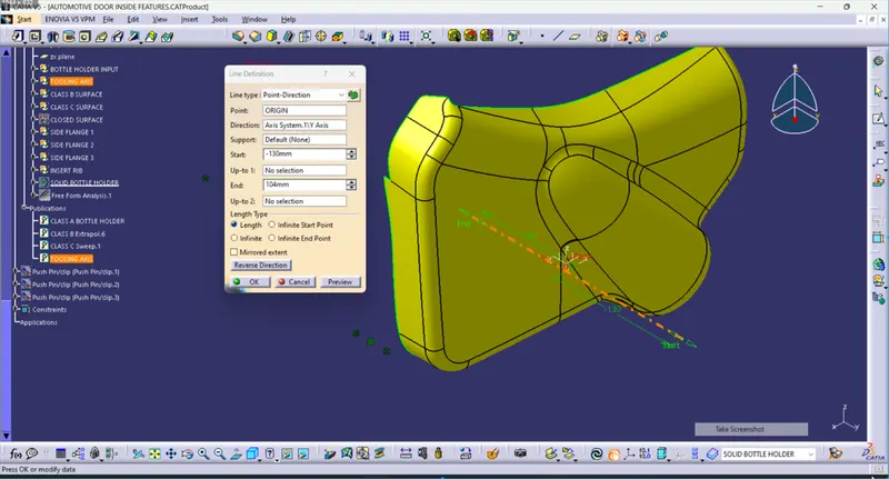
The tooling axis is mainly created from the point and direction method in which the point is stable on a flat surface and direction is taken from the axis system.
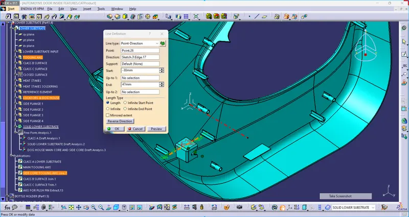
side core tooling axis is taken into consideration for the conditions in which the interference happens during the Dis attachment of dies after the filled melted plastic and there is no way to produce safely plastic parts.
- ARMREST MAIN CORE AND SIDE CORE TOOLING AXIS
- MAP POCKET MAIN CORE TOOLING AXIS
- LOWER SUBSTRATE MAIN CORE AND SIDE CORE TOOLING AXIS
- BOTTLE HOLDER MAIN CORE TOOLING AXIS
5. ROLES OF ADDITIONAL ENGINEERING FEATURE
In order to Join the Bottle Holder with the other bodies, I created 3 Flanges separately with counter holes, Flanges are different based on the engineering features that will be held. Then these flanges are assembled to the main body (Bottle Holder) by a union trim feature.
Similarly, I have created flanges for other parts with heat stakes, locators and dog houses. heat stakes joined the different parts together and locators guide all components and arrest the Degree of freedom so that the component can not move or rotate their own position and can make a stable structure which means the degree of freedom = 0.
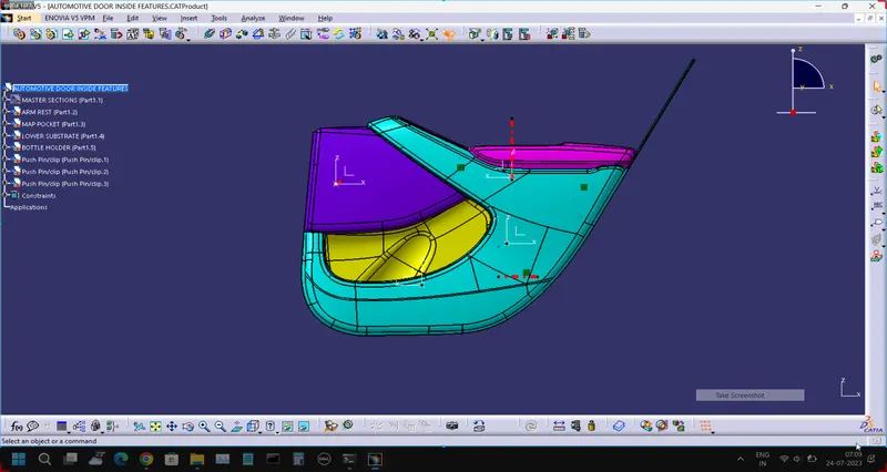
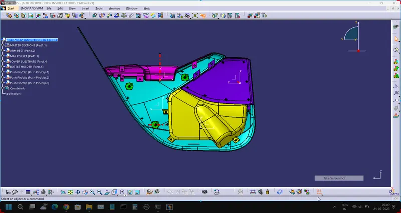
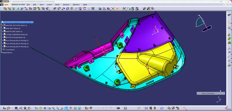
6. SCREENSHOT OF AUTOMOTIVE DOOR TRIM INSIDE FEATURES IN VARIOUS ORIENTATIONS
- FRONT VIEW
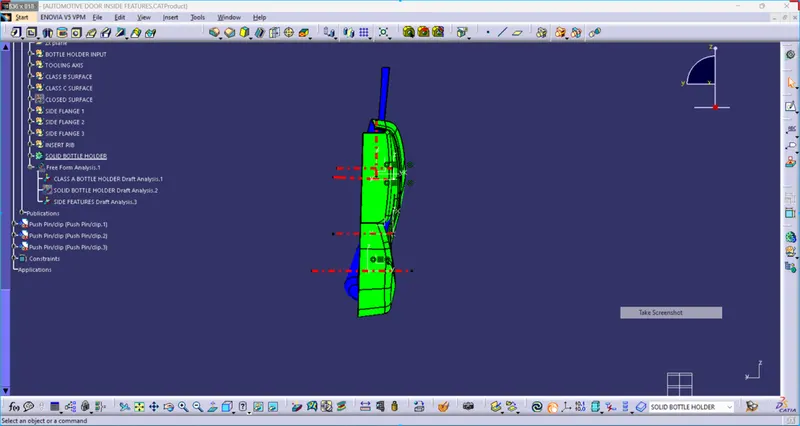
- SIDE VIEW
- TOP VIEW
- ISOMETRIC VIEW