Week -2
1. ELECTRIC DOORBELL
Objective: To study the physical behaviour of the Electric bell
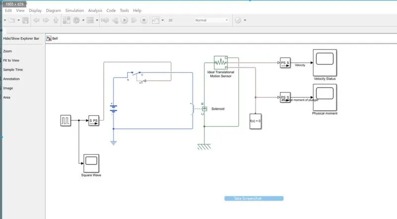
Components of E-bell:
- Battery - you can use 3,6 or 12-volt Batteries which are available on market and this will use for exciting the Solenoid.
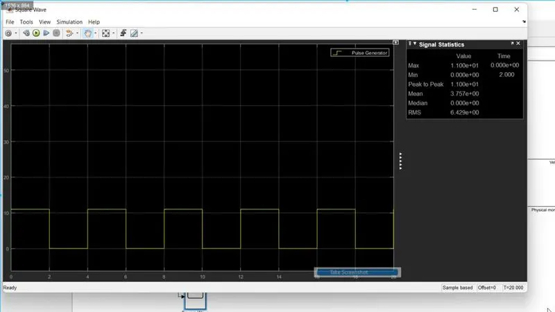
- Pulse Generator - This is used to generate the pulses for 2 seconds so that our Switch can be closed for 2 sec and 2 sec for an open circuit, these pulses are converted into a physical signal and sent to the switch.
- Switch - you can use the SPST switch which can operate by the threshold voltage which is generated by the pulse generator.
Solenoid - this is an electromagnetic to mechanical energy transfer component in which the insulated coating of copper wire winds an iron core.
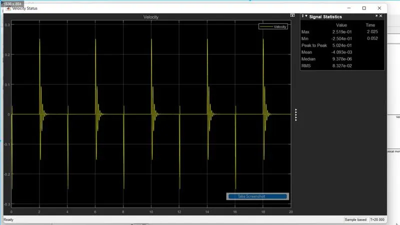
- Ideal Translational Motion Sensor - This sensor will reflect the displacement and velocity of plungers' free end on the graph with their units.
-
Solver - Defines solver settings to use for simulation
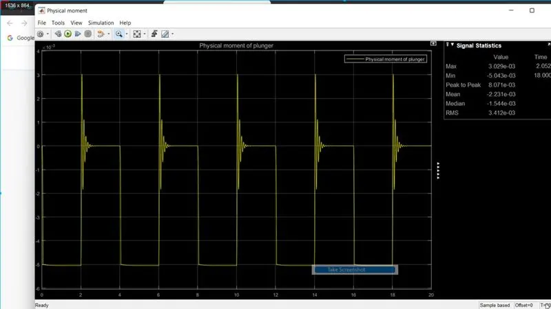
Mechanism - when a battery is connected by the wires end a magnetic field is generated which is applied a pulling force on the plunger (one side is fixed another side is free). But the plunger is temporarily connected (only touch) with the main supply at the end. So If the current is passed through the solenoid, the electromagnetic force is generated in the iron core then a pulling force is generated on the free end of the plunger. Hence suddenly circuit is break because the plunger was temporarily connected by the main supply. so the plunger is returned to its original position due to the Spring constant of the Plunger and again the above process is repeated. Now the plunger is oscillates many times within 2 seconds. I have pinned a mass ball which can strike the bell and produce the sound.
------------------------------------------------------------------------------------------------------------------------------------------------------------------------------------------------------------------------------
Electric doorbell Output:
Pulse Generator:
Velocity Status:
Physical displacement of plunger:
=================================================================================================================================
2. Use a thermistor to sense the temperature of a heater & turn on or turn off the fan as per the conditions
Objective: To Design a cooling system which could cool the Overheated parts of the System
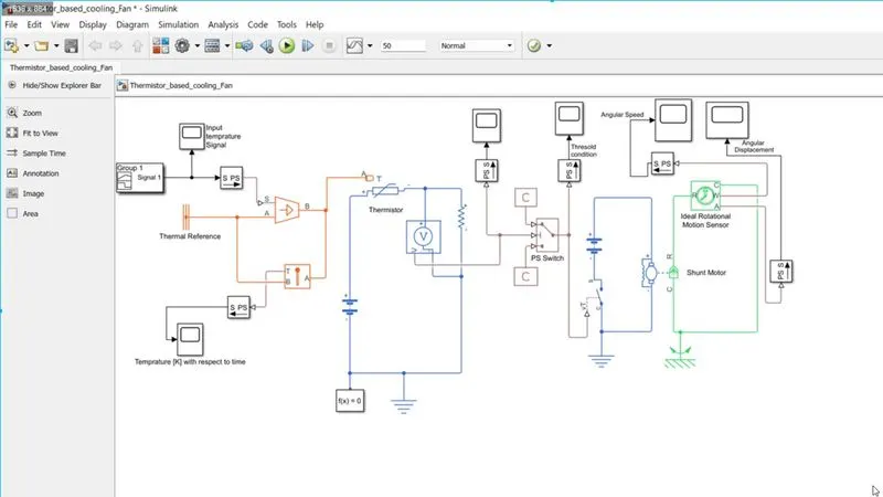
Components:
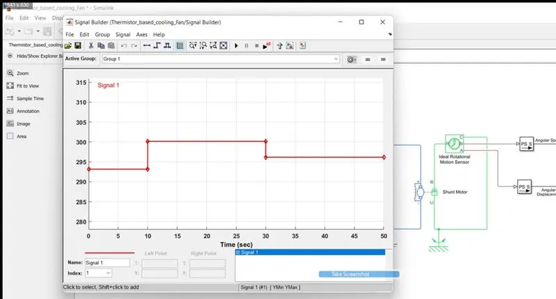
- Signal Builder: according to the requirement we need to build a signal for 0 to 10 seconds at 20 deg C temperature, 10 to 30 seconds at 27 degC temperature and 30 to 50 seconds at 23 degC temperature.
- Controlled temperature Source: This is part of the system which is generating heat so I have to control the temperature of the part so that my system can do smoothly work.
- Temperature Sensor: this will sense the temperature of the heating source.
- Thermistor: This is 2 varieties NTC and PTC. NTC increases the resistance with increasing temperature and PTC decreasing the resistance with increasing temperature.
the thermistor is a device which is thermally sensitive and has resistance increasing or decreasing with respect to temperature.
- Battery: I have used the batteries to operate the electric circuit.
- PS Switch: this physical switch is used for the pass only that value signal which is more than 25 deg C temperature signal so that my next system circuit can work for operating the cooling system.
- SPST Switch: this switch will on when the temperature is above 25 deg C.
- Shunt motor: this motor will rotate for cooling the heated part of the System by a mounted fan.
Mechanism:
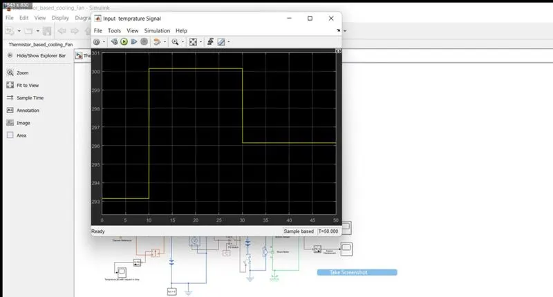
- The signal builder sends the temperature variation with respect to time (0 to 10 seconds 20 deg C, 10 to 30 seconds 27 deg C and 30 to 50 seconds 23 deg C temperature range) then this temp signal sends into the Temperature source via PS converter.
- I used the temperature sensor to check the temperature with respect to time in between temperature sources.
- This heated source is taken close to the thermistor and the thermistor is a thermoelectric device so this device is connected to the electric circuit with a battery.
- thermistor's resistance varies according to temperature so I used the constant resistor to check the voltage and receive the threshold value voltage so that above 25 deg C temperature my cooling fan can start.
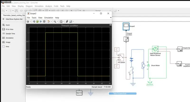
- From the voltmeter, the voltage at both ends of the constant resistor is sent in a Physical switch where I decided the threshold value for the switch will be on/off according to 0 and 1 values that are above 25deg Celsius temperature.
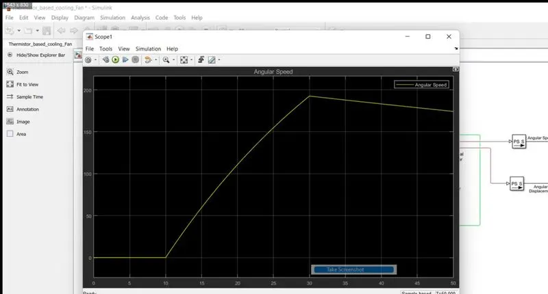
- when the switch is on due to the exceeds of threshold value then this physical signal will act as a key for another Switch of the electric circuit with a battery which is operating the shunt motor cooling fan when a component temperature is above 25 deg C.
------------------------------------------------------------------------------------------------------------------------------------------------------------------------------------------------------------------------------------------
Output for cooling Fan device:
Threshold condition for switching on or off cooling fan:
Angular Velocity of motor fan:
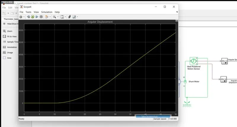
The angular displacement of motor fan position: