Week 12- Final project
FINAL PROJECT
DOOR TRIM PANAL
A door trim panel is a component found on the interior side of a vehicle's door.
Aim:
To create the DOOR TRIM PANAL assembly with the Master Section given as the intersection sketch with the Class A Surface given for individual part and create the Tooling Axis and perform the Draft Analysis for the final solid part.
Output Required:
- Create thickened part using master section for reference
- Create the mounting features as per design guidelines in the industry and with master sections
- Apply material details :
- Draft analysis & Tooling analysis
- Creation of parting lines and check tooling feasibility
A SURFACE PATCH UP:
- Class A Surface is which the part design engineer uses to develop the component with all of the engineering requirements.
- Using Boundary command, check for any discontinuity in the A surface.
Arm Rest:
- Boundary is created along the A surface.
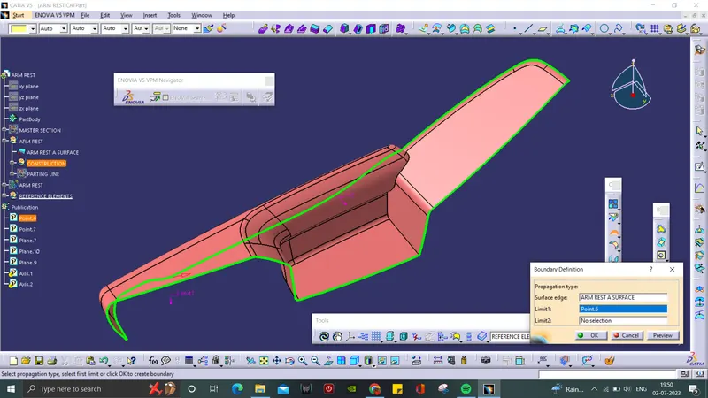
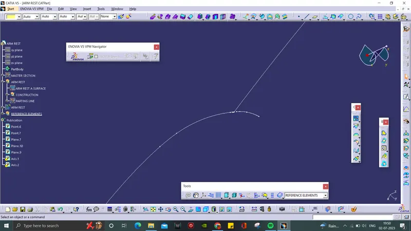
- There is some discontinuity between this area.
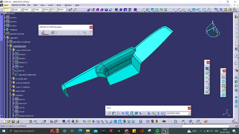
- The A surface is patched up using Extraplate and Trim command.
Lower Substrate:
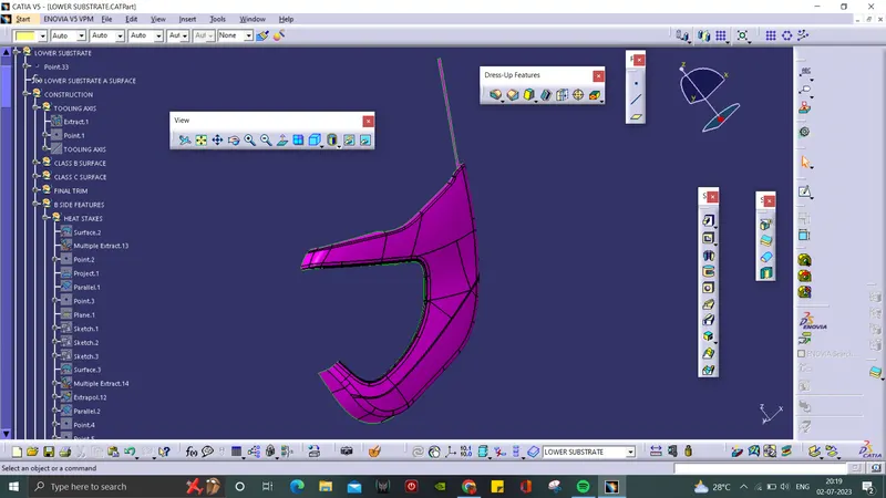
- There is no discontinuity in this surface.
Map Pocket:
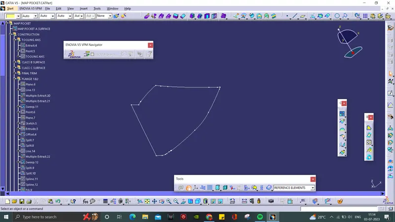
- Created boundary line along the Class A surface.
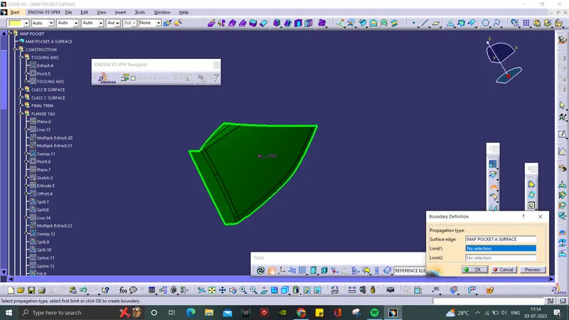
- There is no discontinuity seen in the surface.
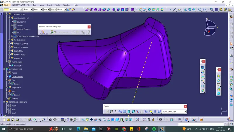
Bottle Holder:
- Boundary line is created through the A surface.
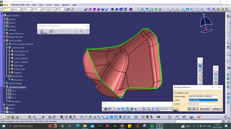
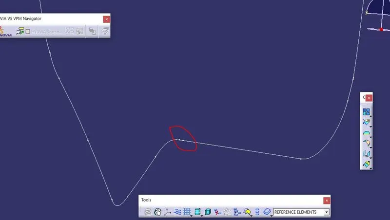
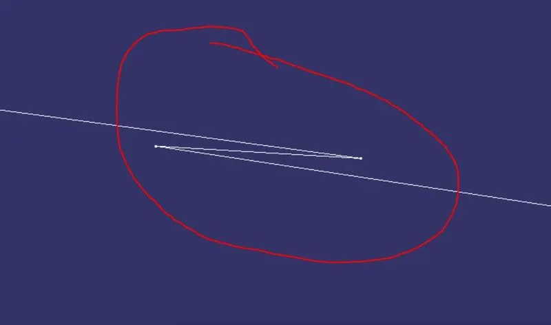
- There is some small discontinuity occurs.
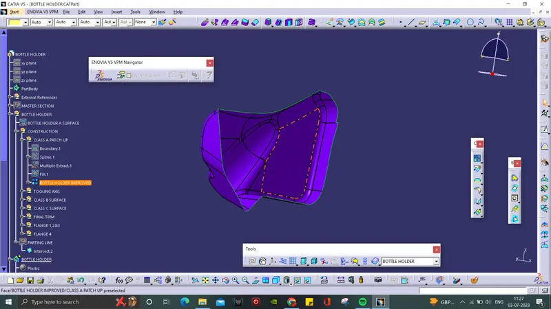
- It is then cleared using spline and fill command.
TOOLING AXIS:
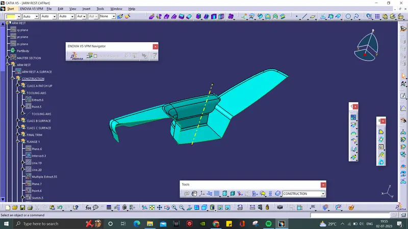
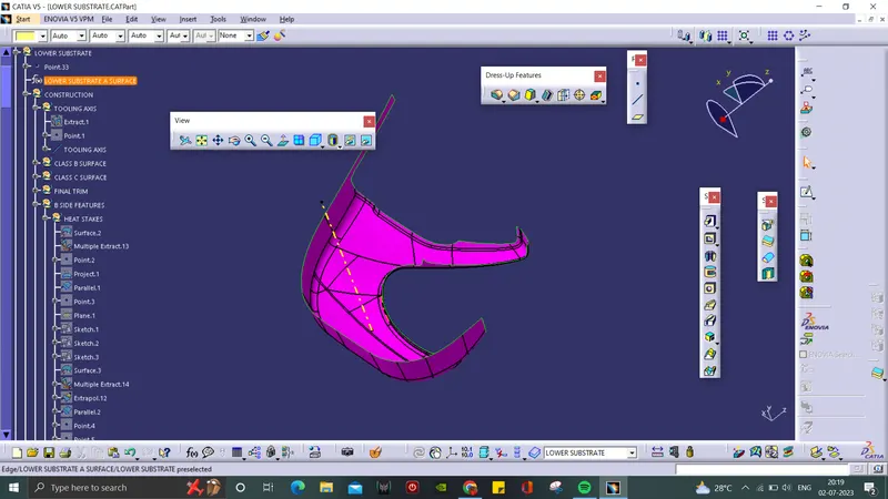
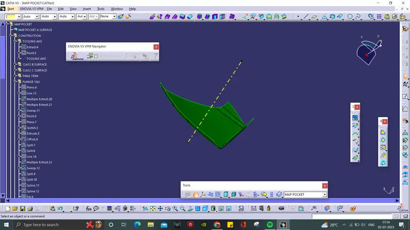
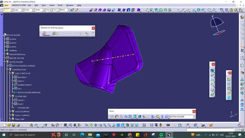
- Tooling Axis is the direction in which a core or cavity of mold opens. This axis is very important to determine the orientation of the component in mold, core and cavity design as well as to run the Draft Analysis of the component.
- In this case, we took y axis as the tooling direction and the axis is created from the center point extracted from the A surface.
Arm Rest:
Lower Substrate:
Map Pocket:
Bottle Holder:
CLASS B SURFACE:
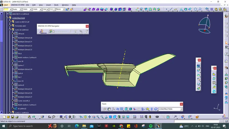
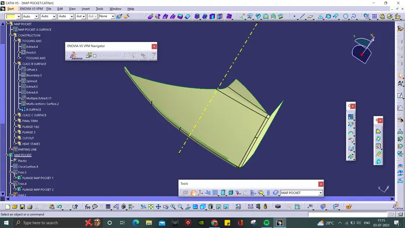
- Since the component thickness is 2.5mm, the A surface is Offsetted by 2.5mm.
- Some discontinuities will happen which is then repaired by using Muti-section, Fill and Trim commands.
- At the end, all the surface are joined together to form Class B Surface.
Arm Rest:
Lower Substrate:

Map Pocket:
Bottle Holder:
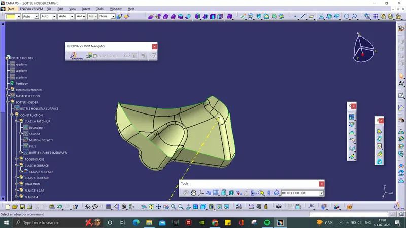
CLASS C SURFACE:
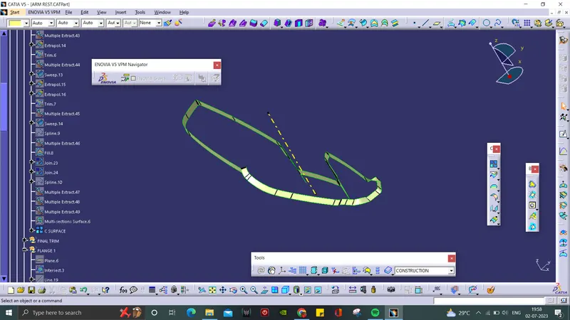
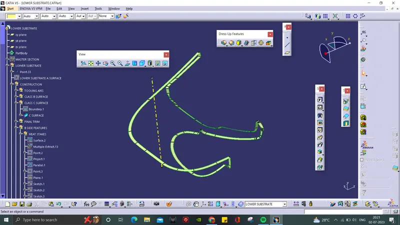
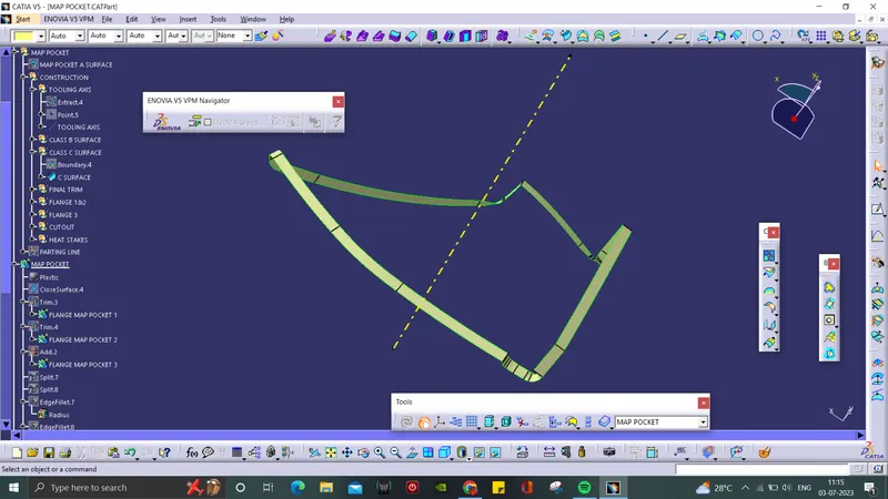
- A boundary was created along A surface.
- The boundary as guide curve Sweep is used to form Class C Surface with A surface as reference surface.
Arm Rest:
Lower Substrate:
Map Pocket:
Bottle Holder:
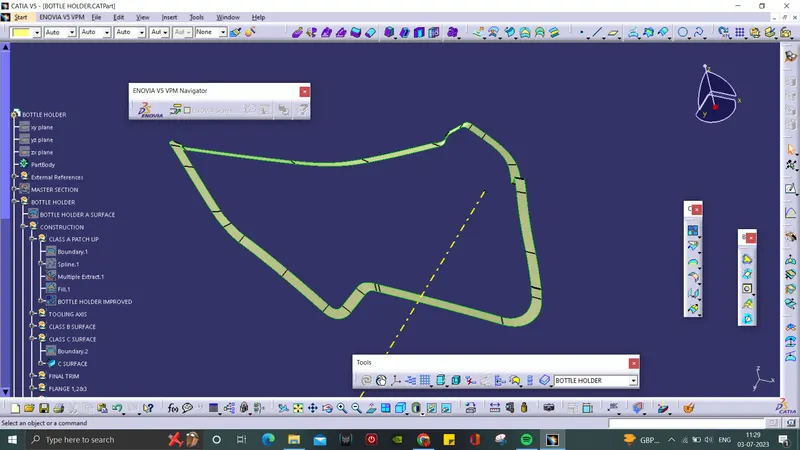
FINAL TRIM:
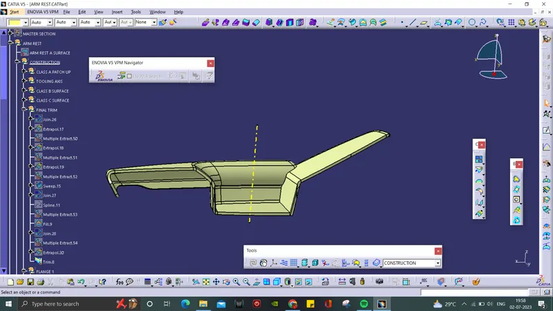
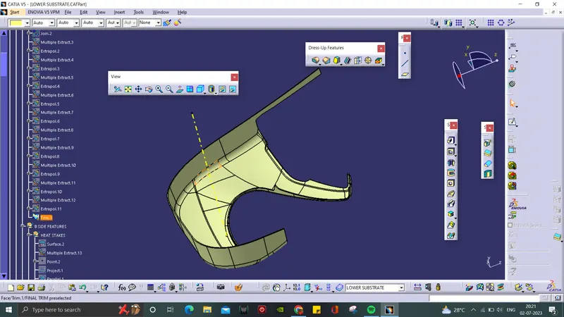
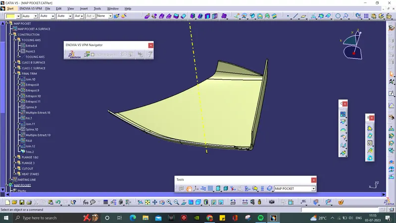
- At the final trim part, the A surface and C surface are joined together.
- B surface is Extraplated and then Trimmed with A and C surface to form the Door Trim Panal surface.
Arm Rest:
Lower Substrate:
Map Pocket:
Bottle Holder:
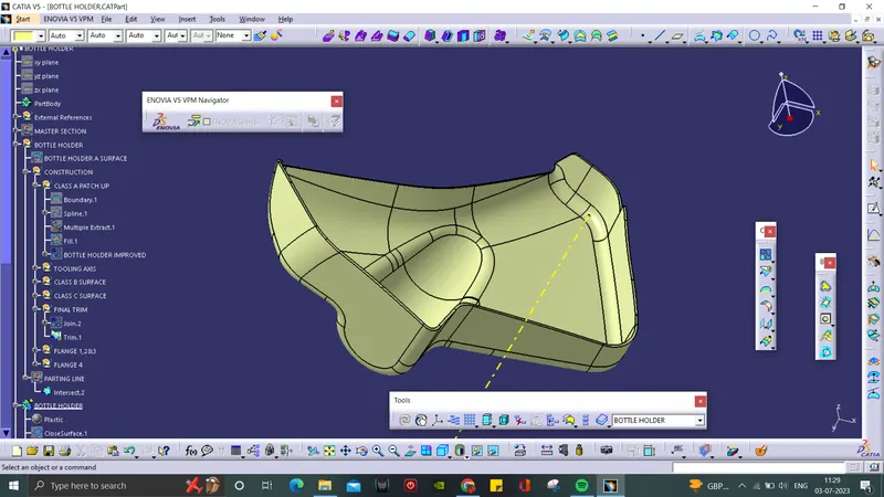
SOLID SURFACE:
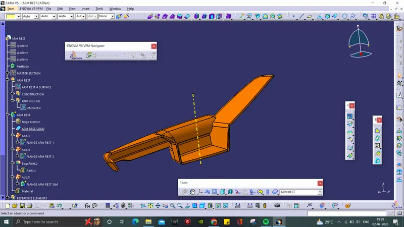
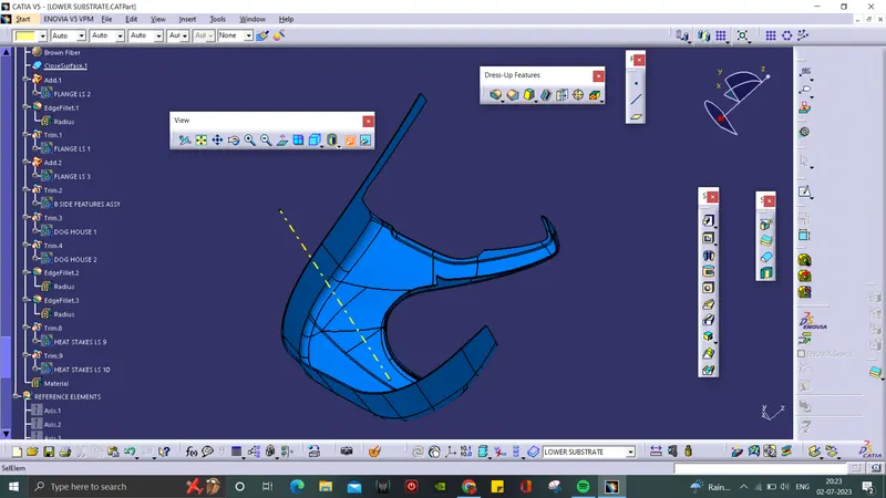
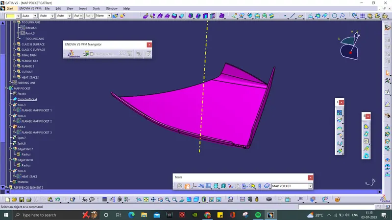
- At part design, the trimmed surface is converted into a solid Door Trim Panal by using closed surface command.
Arm Rest:
Lower Substrate:
Map Pocket:
Bottle Holder:
B-SIDE FEATURES:
- B-side features refers to the components that are created on the opposite side of the parting line in an injection-molded plastic part.
- These features are typically found on the side of the part that is not directly visible when the part is assembled or in its final form.
- B-side features are important to consider when designing plastic parts for manufacturing, as they can affect the mold design, part ejection, and overall functionality
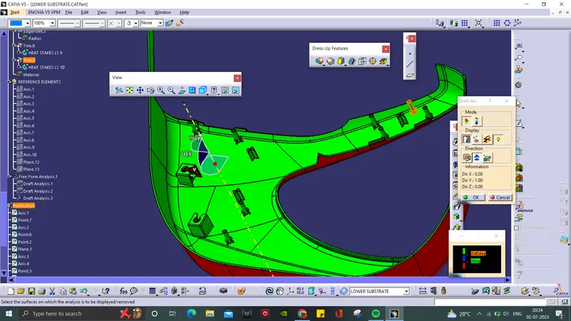
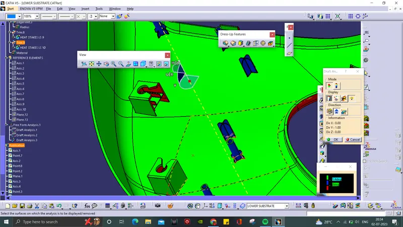
- The minimum draft angle for the b-side features are 0.5 deg.
Lower Substrate:
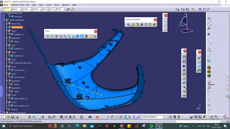
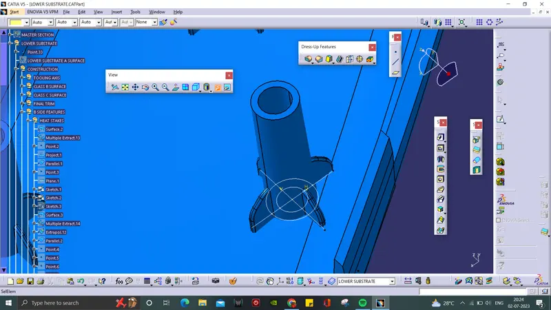
Heat Stakes:
- The reference points are created, required sketch is drawn.
- The sketch is padded and drafted to 0.5 deg.
- A rib for the Heat Stakes is created in sketch and padded.
- The rib is then trimmed with the Heat Stakes solid.
- Like that, 10 Heat Stakes are created by translation using reference points.
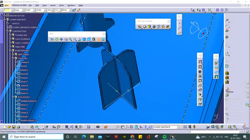
Locators:
- 4 way locators are used here.
- The reference plane is taken is required area and sketch is drawn.
- It is padded using thick component and then drafted, chamfered and filleted.
- Totally, 4 Locator is created using translation method.
Dog House:
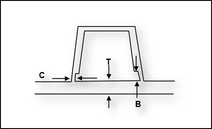
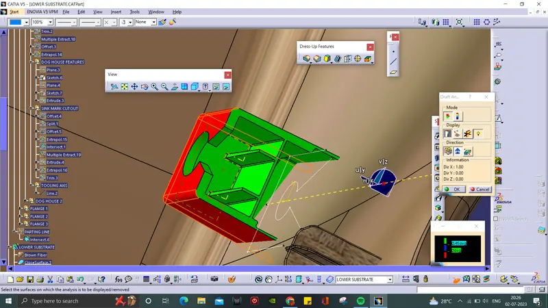
- The minimum draft angle of the outer walls of the dog house should be 1.5 deg and inner wall of 0.5 deg.
- The wall(C) should be 40% or less than the part thickness(T).
- The height(B) should between 3-6 mm.
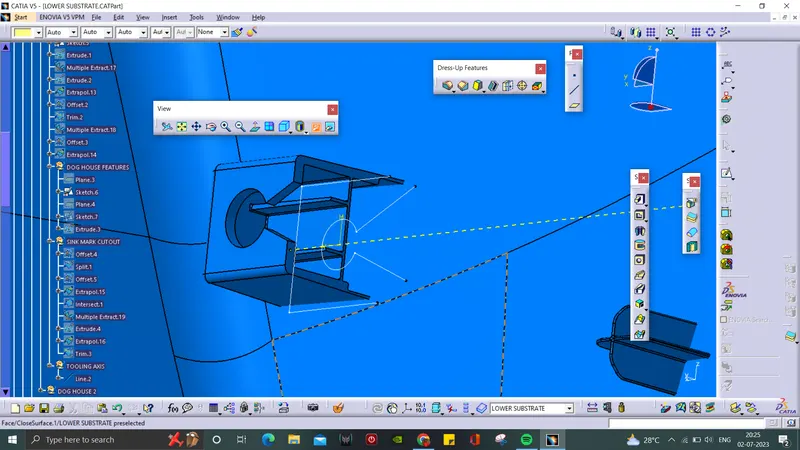
- The base surface is extracted and a plane is created through the surface.
- Dog house sketch is drawn and extruded.
- The base is then offsetted at the top of extrude to close the top.
- Then thicksurface is used to make it solid.
- It is then drafted and filletted through the axis created for doghouse.
- Finally, the Dog House is assembled with the Lower Substrate.
- Another Dog House is created using translation method.
Map Pocket:
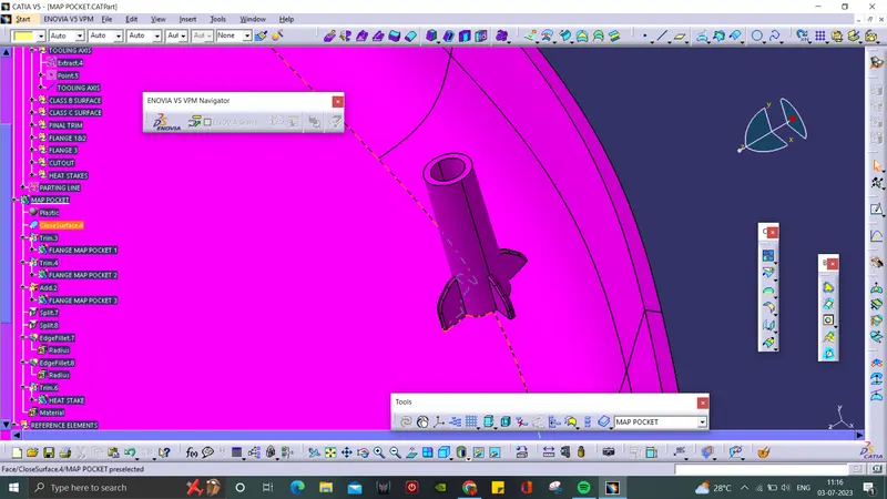
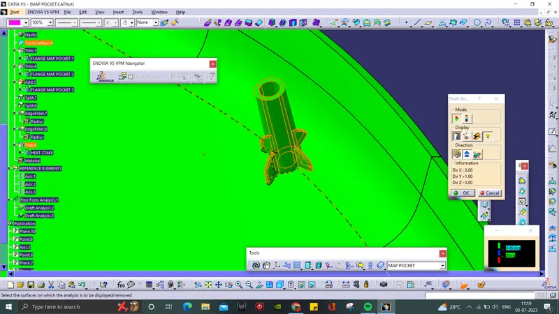
- A single heat stake is created in the map pocket to give extra support to bottle holder.
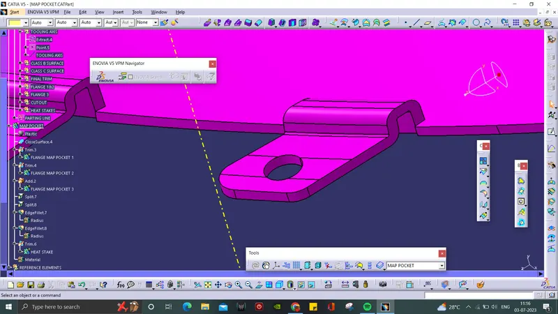
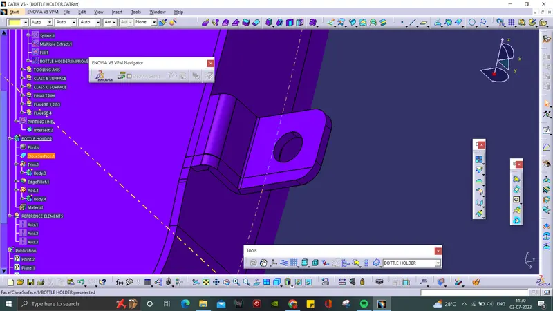
FLANGES:
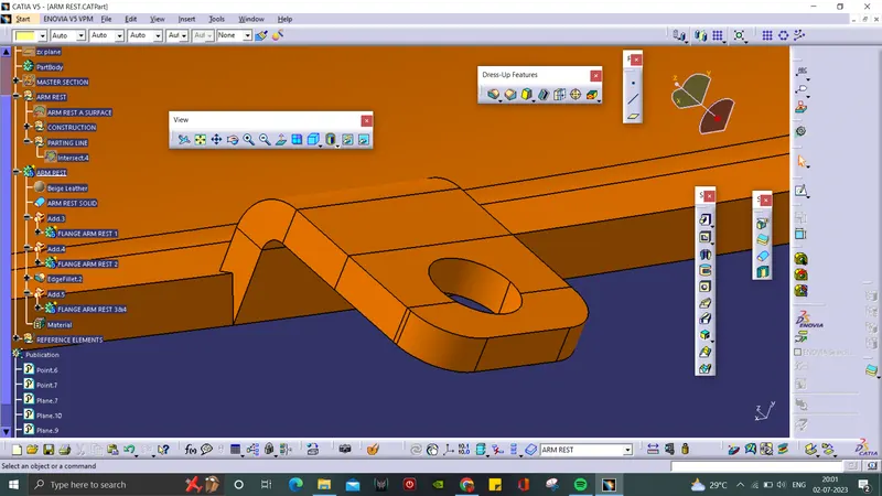
- These flanges are the extending supporting part of the solid body that heat stakes can fit into it.
- It is created using Master Section.
- 4 flanges are created along the individual parts.
Arm Rest:
Map Pocket:
Bottle Holder:
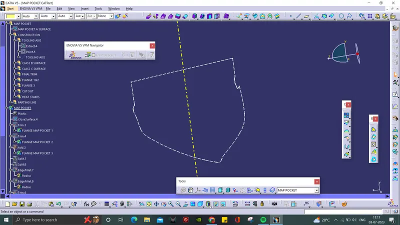
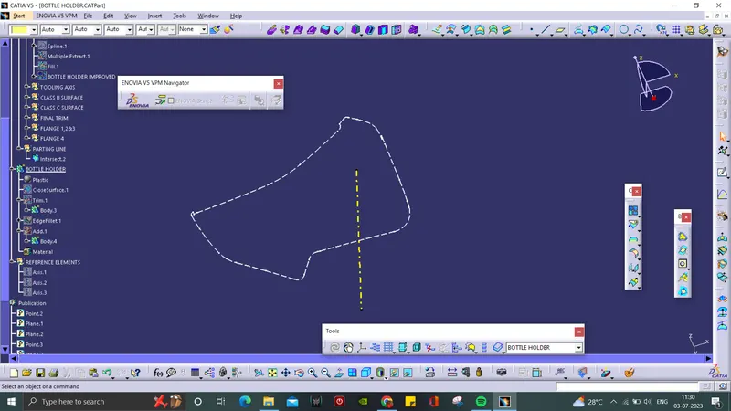
Parting Line:
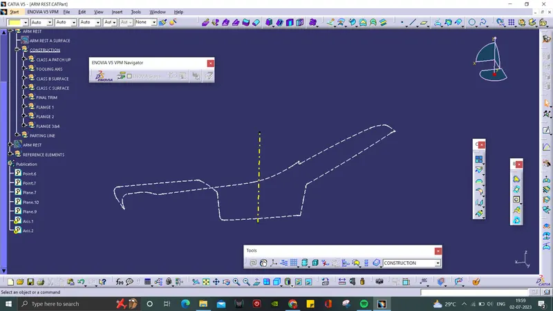
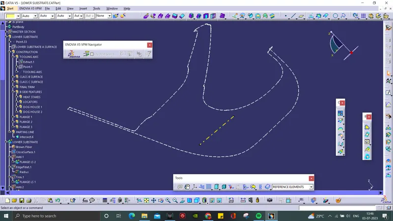
- Parting line are the seal or partition between the core and cavity.
- It should not be in the visible side.
- So, the parting line is created by the intersection between C surface and B surface.
Arm Rest:
Lower Substrate:
Map Pocket:
Bottle Holder:
Material Applied:
- Materials can be applied using "Apply Material" command in the part design.
- A set of different types of materials will given.
- Select the required material from the dialog box.
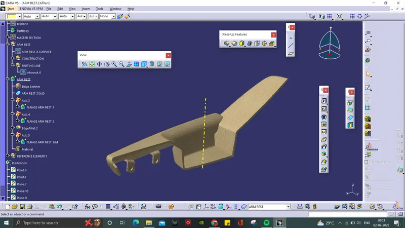
Arm Rest:
- Beige leather is choosen as the Arm Rest material.
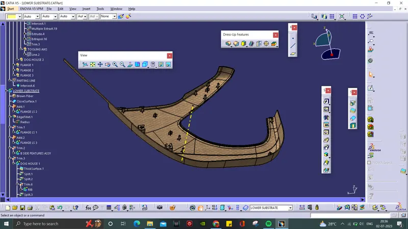
Lower Substrate:
- Brown Fiber is choosen as the Lower Subrate material.
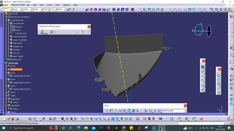
Map Pocket:
- Plastic is choosen as the Map Pocket material.
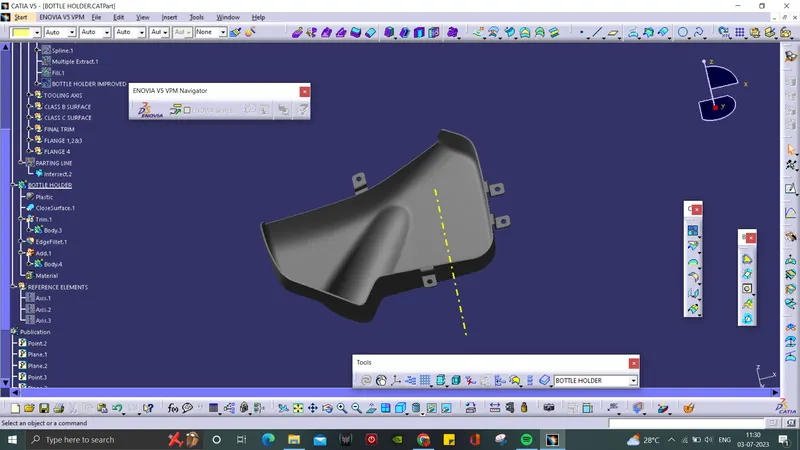
Bottle Holder:
- Plastic is choosen as the Bottle Holder material.
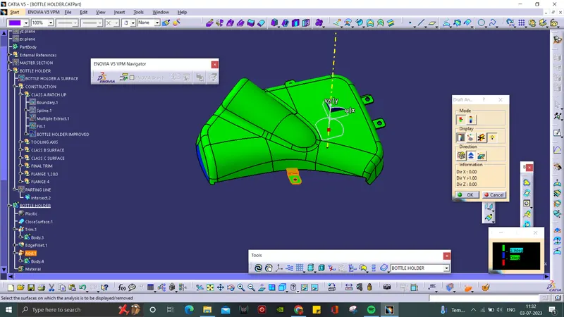
Draft Analysis:
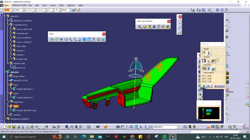
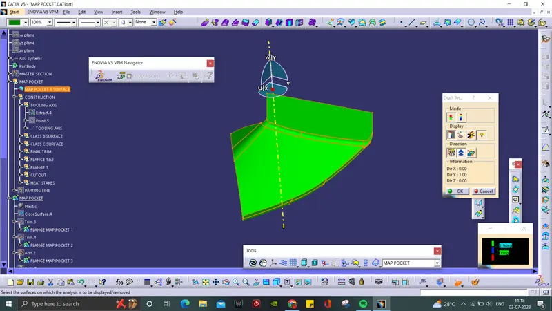
- In Draft Analysis tool bar, use the compass and drag it to set along the Tooling Axis of the surface.
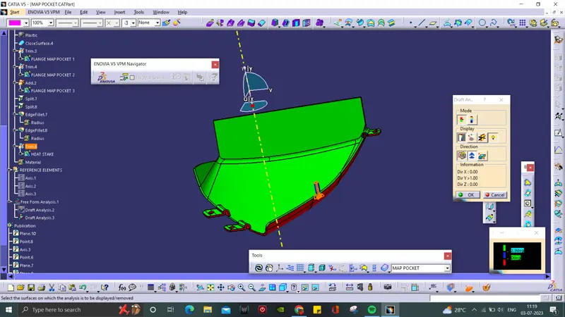
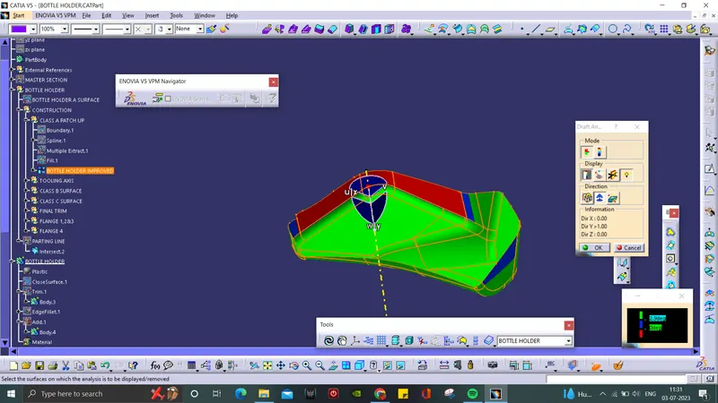
- By clicking the surface, it will turn into green colour. if it is blue, the analysis was inversely done which is corrected just by flipping the direction.
- Draft Analysis on the solid part is in green and red regions.
- Individual Draft Analysis is done for both solid and surface.
Arm Rest:
Class A Surface- 3 deg

Arm Rest Solid- 3 deg
Lower Substrate:
Class A Surface- 3 deg
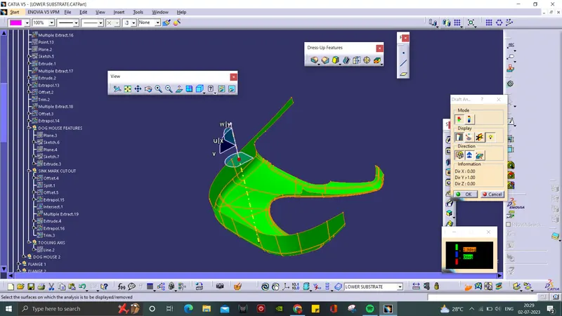
Lower Substrate Solid- 3 deg
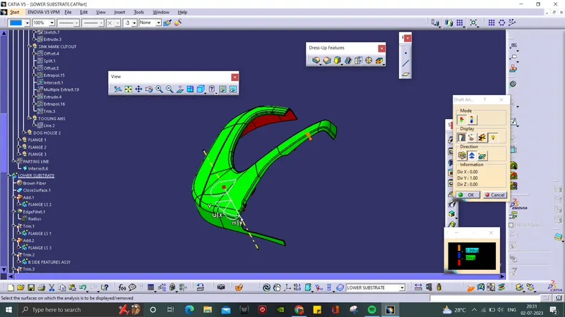
B-side Features- 0.5 deg
Dog house Outer walls- 1.5 deg
Side Core Axis:
- Dog House Draft Analysis for inner side is done through the Side Core Axis with 0.5 deg.
Map Pocket:
Class A Surface- 3 deg
Map Pocket Solid- 3 deg
Heat Stake- 0.5 deg
Bottle Holder:
Class A Surface- 3 deg
Bottle Holder Solid- 3 deg
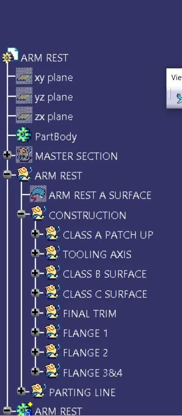
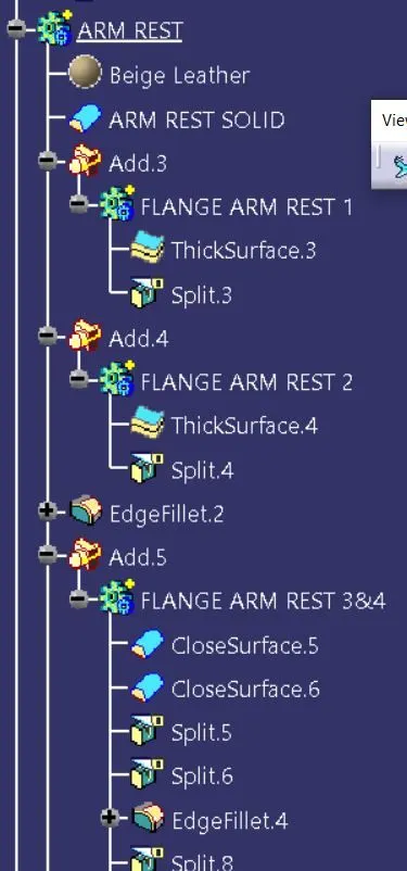
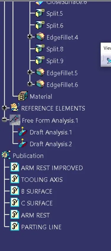
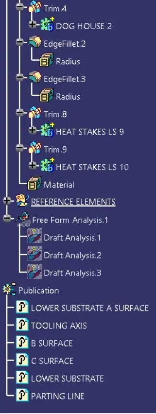
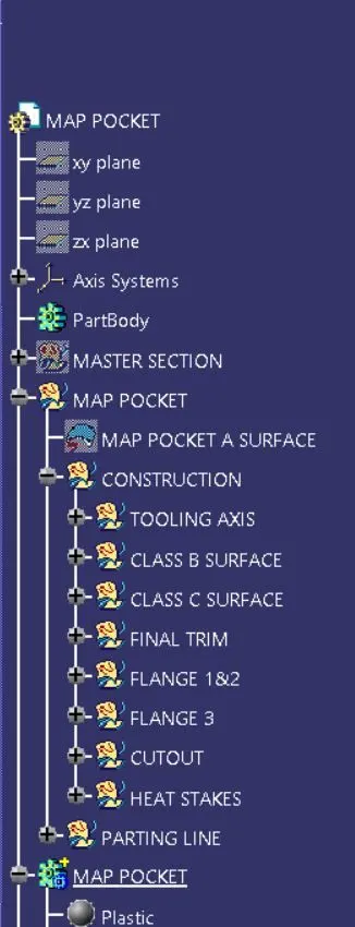
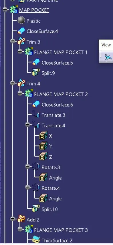
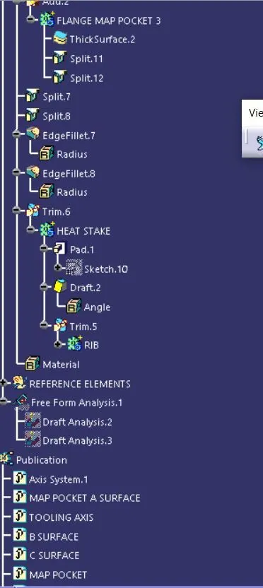
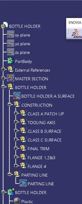
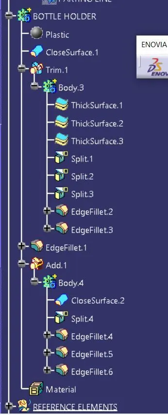
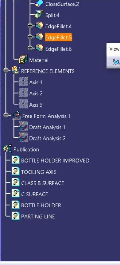
TREE STRUCTURE:
Arm Rest:
Lower Substrate:
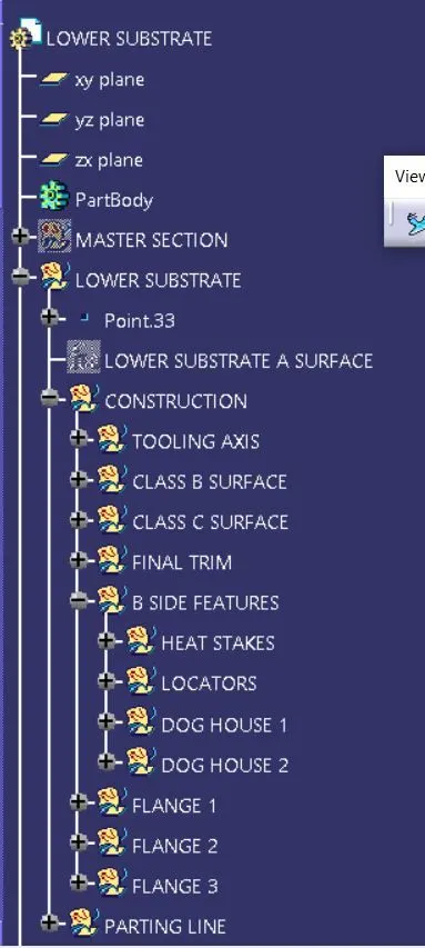
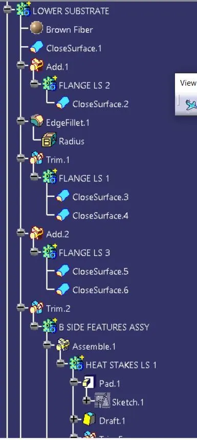
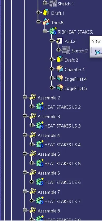
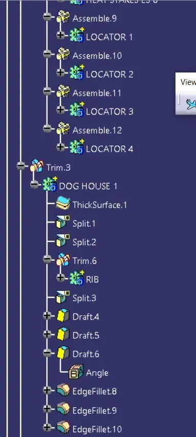
Map Pocket:
Bottle Holder:
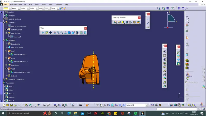
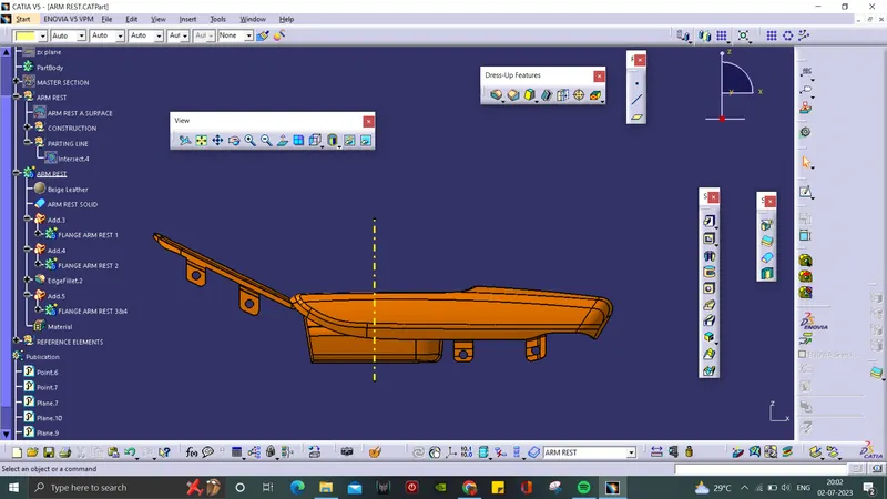
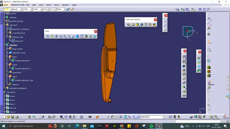
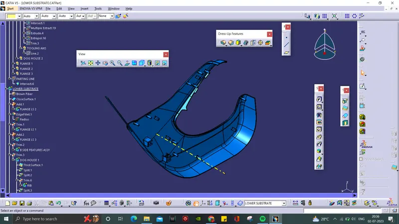
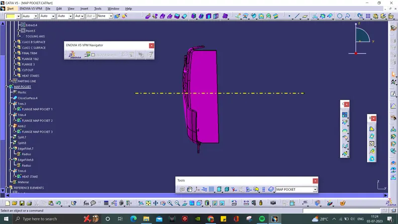
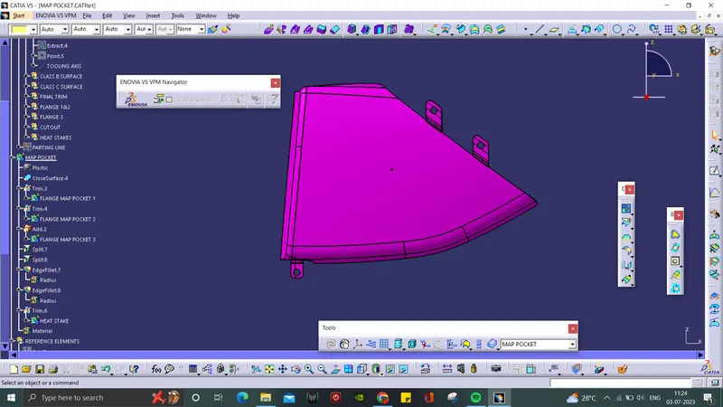
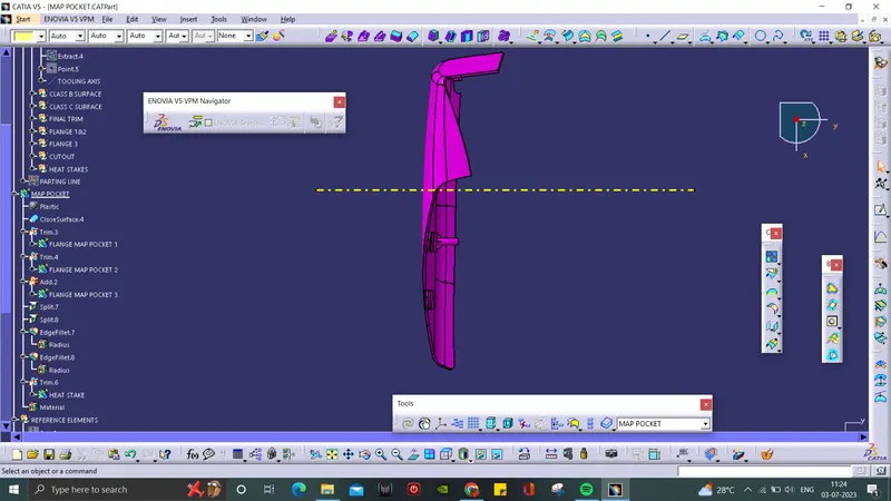
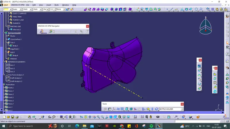
3D VIEWS:
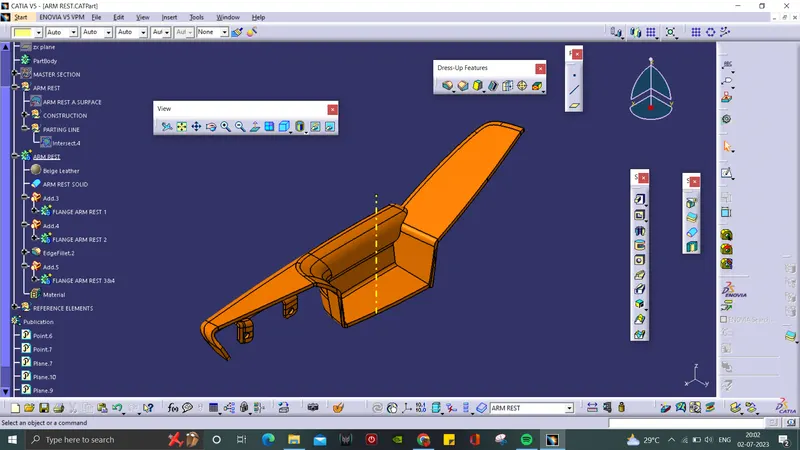
Arm Rest:
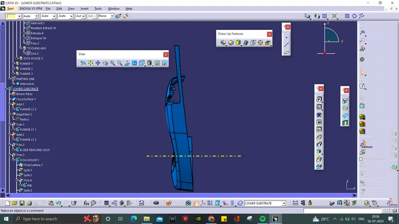
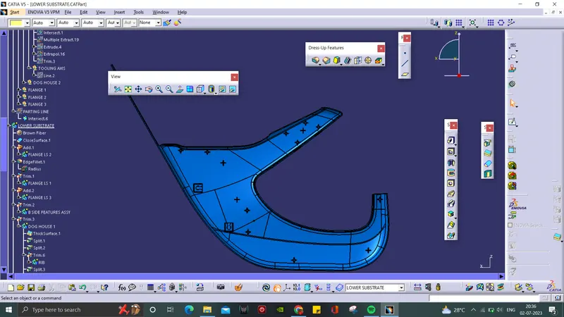
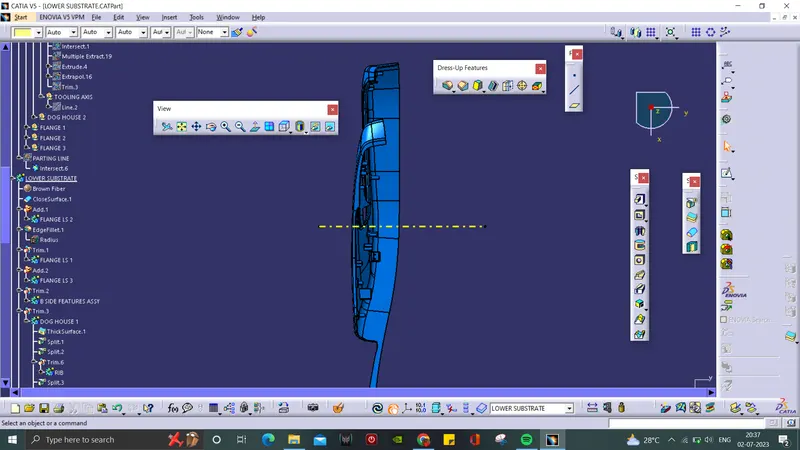
Lower Substrate:
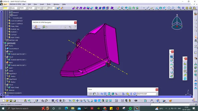
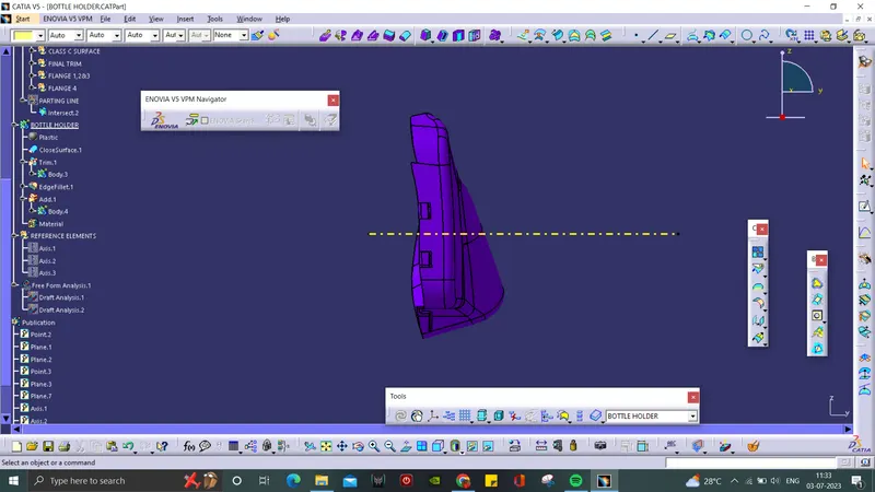
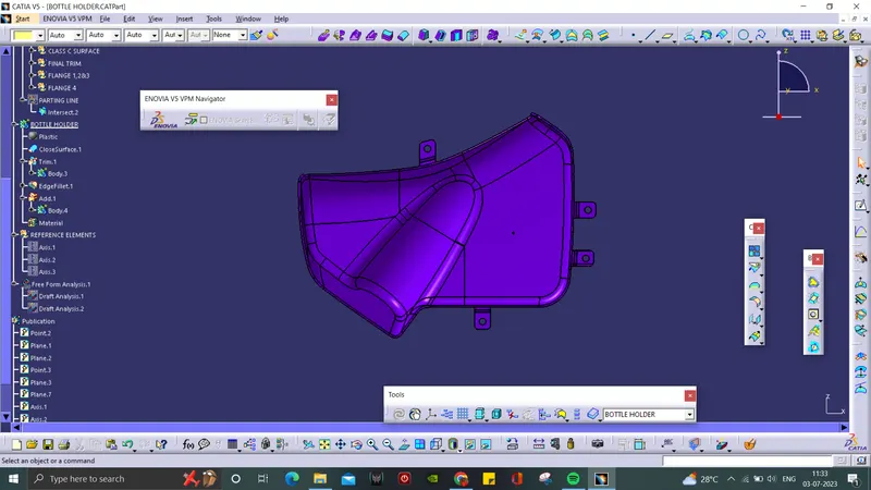
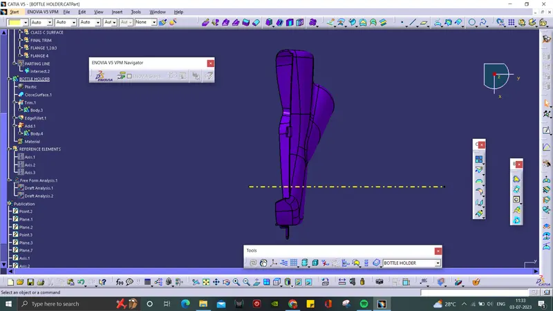
Map Pocket:
Bottle Holder:
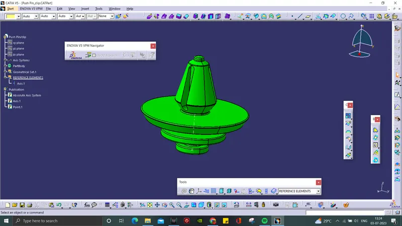
PUSH PIN/CLIP:
- It is a fastener used to secure the components of a dog house together.
- Reference axis were created for assembly
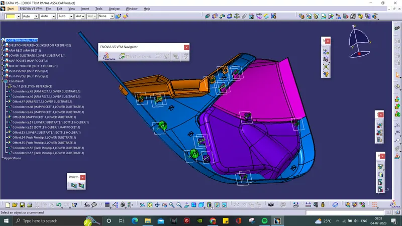
DOOR TRIM PANAL ASSEMBLY:
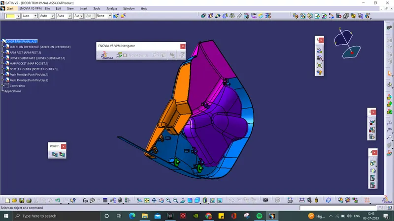
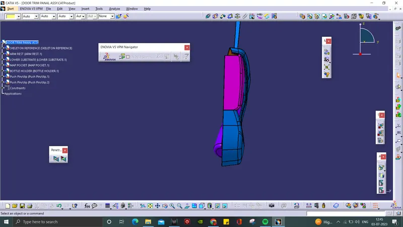
- In this workbench, the Door Trim Panal parts like Arm Rest, Lower Substrate, Map Pocket and Bottle Holder were assembled together.
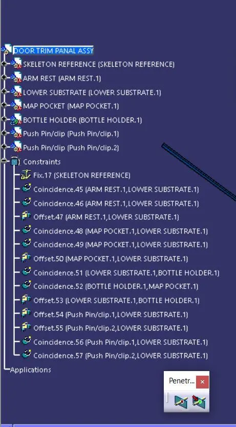
Assembly Constraints:
- Multiple constraints were used to assemble together.
Isometric View:
Front View:
Top View:
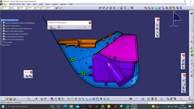
Side View:
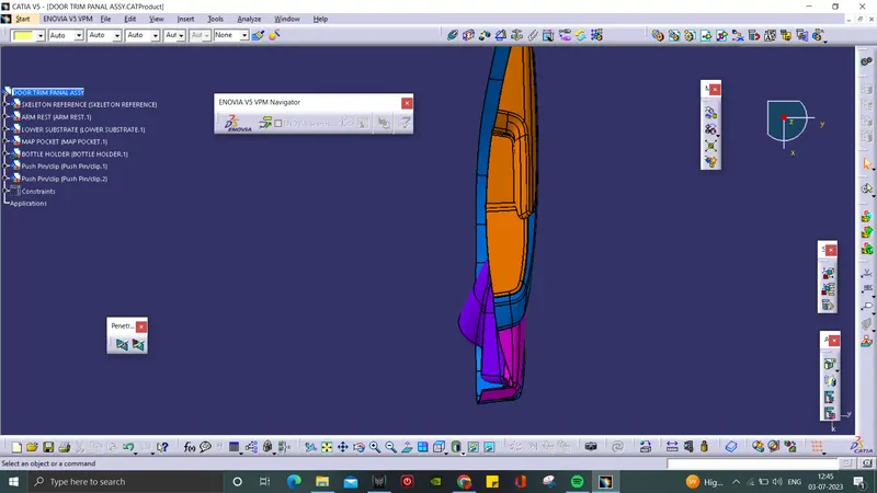
CONCLUSION:
The required A,B and C surfaces are developed, draft analysis were done for all parts and the parts were assembled together.