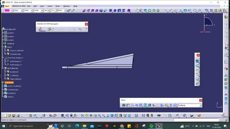
Week 9 - Challenge 1 - Base Bracket Design
To create tooling axis for the given Class A surface:
- Visually check which of the axis is best possible by looking the shape of the component.
- Z axis is the best possible tooling axis among X and Y.
- The centre hole is taken as reference and a dummy tooling axis was created.
- Create an intersection pattern to the plane on the dummy tooling axis.
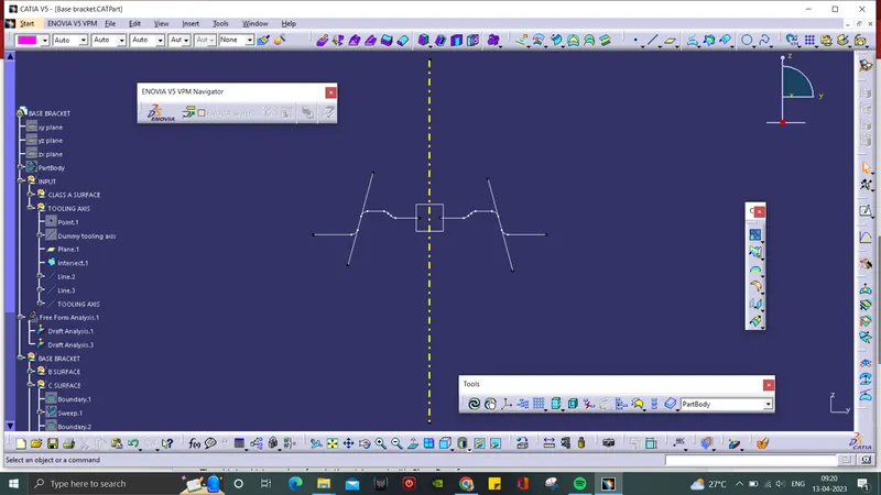
- The two slopes on the either side of the intersection was used to create two more lines and after that create a bisector line along the two lines which became the main Tooling Axis.
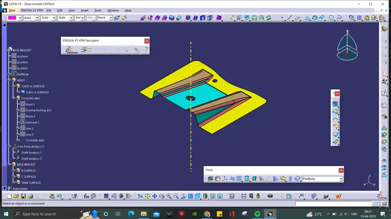
To create Class B surface:
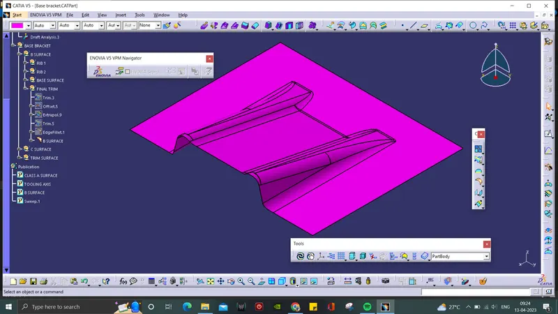
- At first, the Class A surface is extracted which is untrimmed, extrapolated and trimmed to give the following Rib.
- Same way done on other rib, and then the two sides are offsetted by 2.5mm.(i.e Thickness=2.5mm)
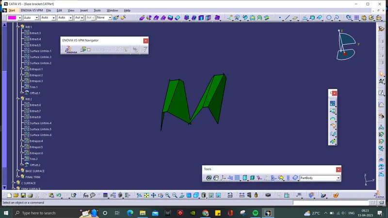
- The centre region was also extracted and offsetted tp 2.5mm.
- Which is trimmed with the two Ribs to create the following shape.
- The base region is also extracted and trimmed with other region.
- The surface was fillteted to give the Class B surface.
To create Class C surface:
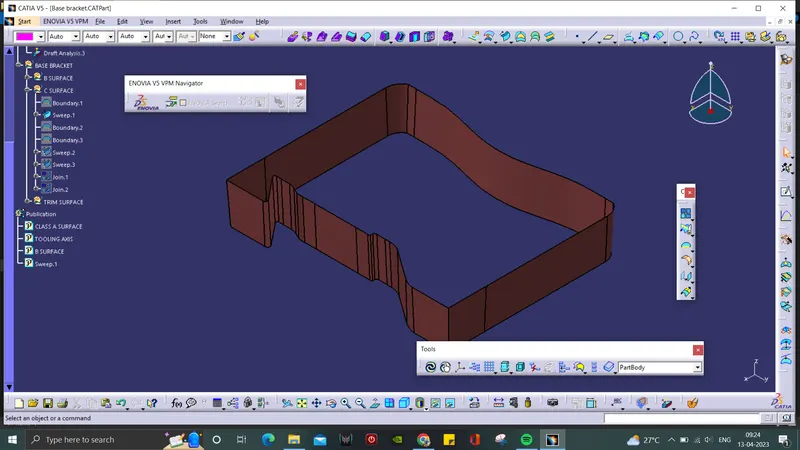
- The boundary was created using Class A surface.
- With reference to the tooling axis sweep command was used along the boundary to create Class C surface along the required direction.(draft angle=3mm)
- Similarly, the two holes are swept along the same direction.
To create the final trim:
- The above Class C surface and the holes were trimmed with Class A surface.
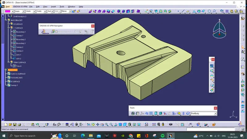
- The obtained trimmed surface is then trimmed with Class B surface.
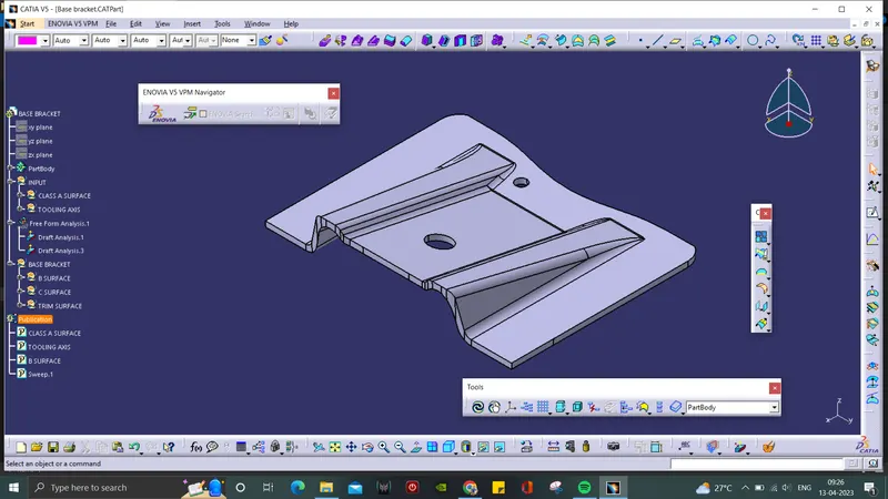
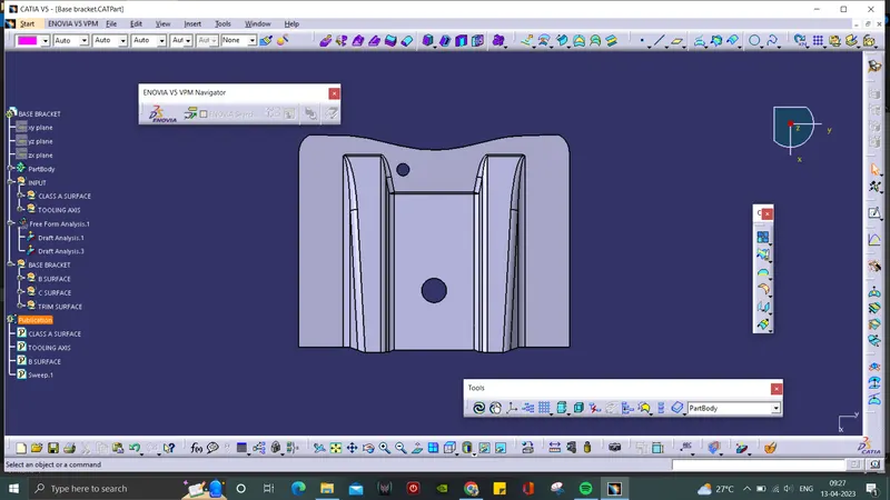
- It is the final Brace Bracket component.
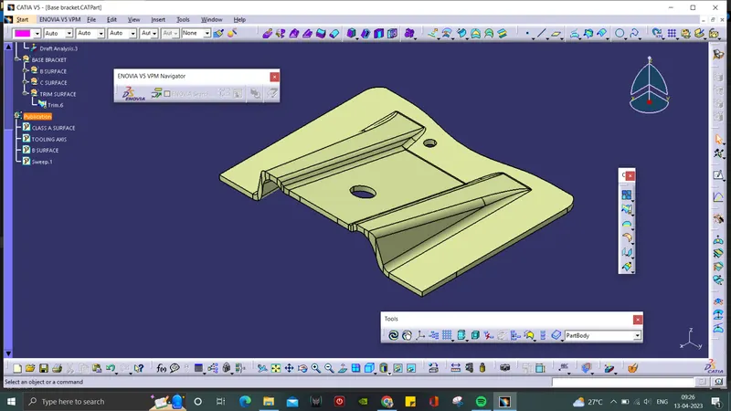
- The surface was made as solid body by using close surface command in part design.
To create Draft Analysis:
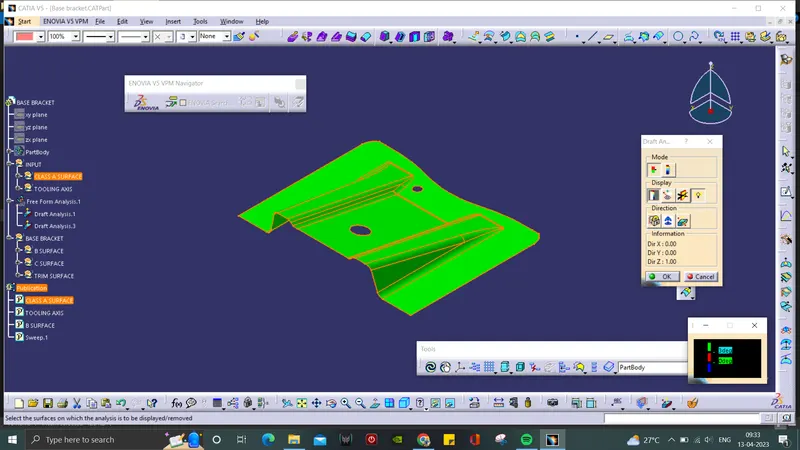
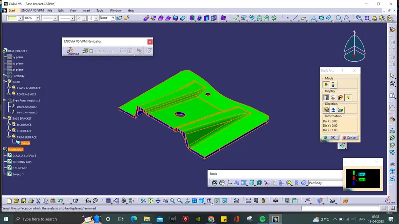
- The draft analysis angle that is considered in the OEMs is 3 degree.
- In draft analysis tool bar, use the compass and drag it to set along the tooling axis of the surface.
- By clicking the surface, it will turn into green colour. if it is blue, the analysis was inversely done which is corrected just by flipping the direction.
- Draft analysis on the solid part is in green and blue regions.
3D VIEWS:
ISOMETRIC VIEW:
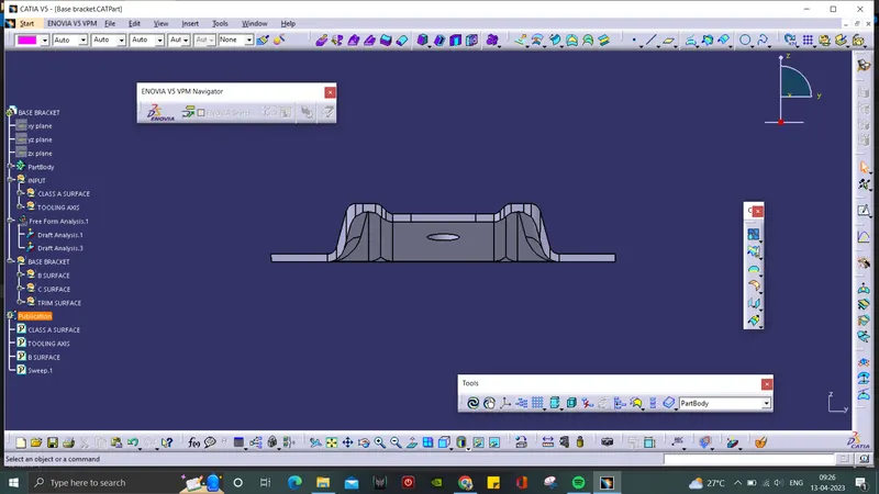
FRONT VIEW:
TOP VIEW:
SIDE VIEW: