Week 9 - Challenge 3 - Bumper
I CAN'T FINISH WITHIN TIME......
TOOLING AXIS:
- A geometrical set for Tooling Axis is created and base is extracted as referance surface.
- The projection of the Class A surface is taken and from that a bisecting line is formed which is the first referance line for Tooling Axis.
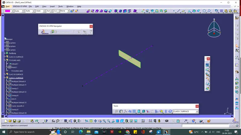
- For second referance line, a line is drawn from and angle of 6 from the center wall.
- Then by bisecting the two lines we get the Tooling Axis.
CLASS B SURFACE:
- For B surface, individual geometrical set is created for the Bumper, Walls and Base.
- Then they are extracted along the geometrical set.
- The extracted surface are then untrimmed and extrapolated by 50mm to form extended surface.
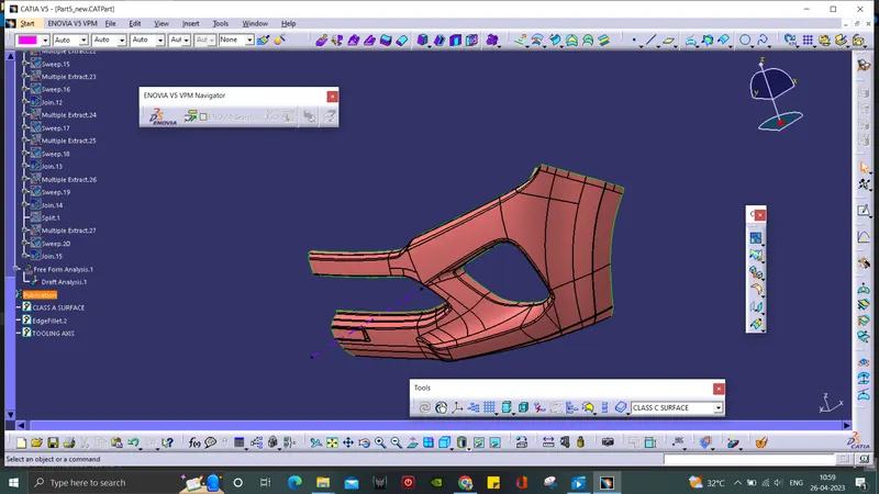
- At last, all the extracted surface are trimmed together and filleted to form Class B surface.
CLASS C SURFACE:
- Mutiple extract is used to form the boundary along the A surface.
- Then the boundary was made into surface by using sweep with and draft angle of 3 by one on the inside and other on the outside.
- The two boundaries were extrapolated and trimmed to form Class C surface.
FINAL TRIM:
- At the final trim part, the A surface and C surface are extrapolated and trimmed together.
- The surface we get above is them trimmed with the B surface to form the Bumper surface.
- Then at part design, the hollow part is converted into a solid Bumper by using closed surface command.
DRAFT ANALYSIS:
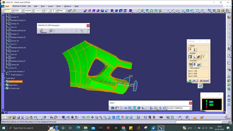
- In Draft Analysis tool bar, use the compass and drag it to set along the Tooling Axis of the surface.
- By clicking the surface, it will turn into green colour. if it is blue, the analysis was inversely done which is corrected just by flipping the direction.
- Draft Analysis on the solid part is in green and red regions.
- Individual Draft Analysis is done for both solid and surface.