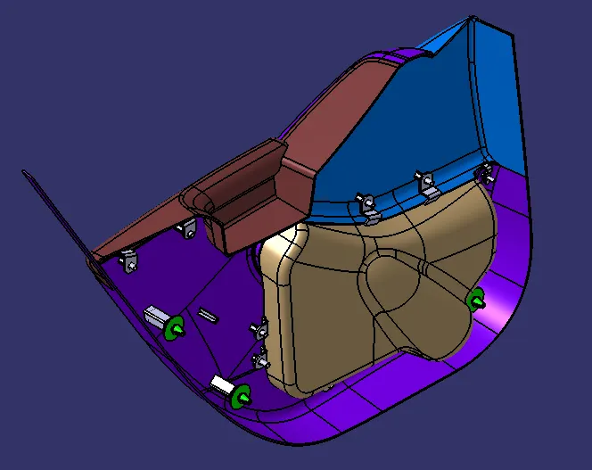
Week 12- Final project
AIM: -
In this project, we create the door trim panel components (Lower Substrate, Arm Rest, Bottle Holder, Map Pocket) with the necessary input surfaces provided and generate the required B side features (Heat Stakes, 4-Way Locators, Dog Houses, Push Clips, Ribs, Screw Bosses, and so on) and then assemble the individual components of the door trim by providing proper constraints and performing the appropriate draft analysis using CATIA V5 Software.
OBJECTIVE: -
The main goal is to create the individual components of the door trim using the input Class A surface, generate the Class B and Class C surfaces, and produce the solid surface body out of it, as well as perform the proper draft analysis with the required draft angle of 3 degrees for the body, and then repeat the procedure for the remaining components. Then, using the CATIA V5 Software, begin creating the B-side features of the elements by referencing the master sections provided, perform the draft analysis with an input draft angle of 0.5 degrees, and assemble the components for the final door trim panel on the assembly workbench by providing necessary constraints.
PROCEDURE: -
- Examine the given input surface.
- The surface of Class A improvision.
- Creation of a Tooling axis.
- Class A surface draft analysis.
- Creation of a Class B surface.
- Creation of a Class C surface.
- Creation of a solid surface body.
- Draft Analysis of the solid body.
- Creation of the B side features.
- Draft Analysis of the solid body, including B-side characteristics.
- Creation of Parting Line
GIVEN INPUT
CLASS A SURFACE
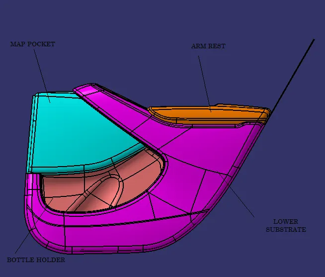
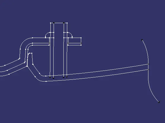 |
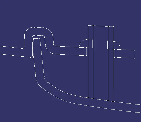 |
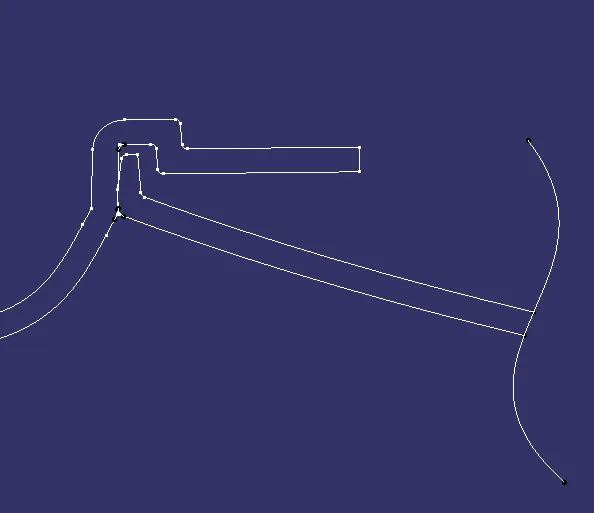 |
| MASTER SECTION 1 | MASTER SECTION 2 | MASTER SECTION 3 |
RULES TO FOLLOW
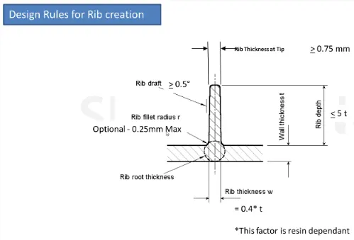
- Draft: 0.5 degrees per side (minimum) and up to 1.5 degrees maximum.
- Rib thickness: 40 to 50% of wall thickness
- 5 times the thickness of the wall in height
- Steel height/width ratio (maximum): 3:1 (for more than one rib). h/w = 3 or 2 (recommended), where h is the rib's height and w is the distance between two ribs.
- 0.75mm is the minimum thickness at the tip.
- Rib fillet Radius: 0.25mm maximum or 0.125*component thickness
- Rib root thickness should not exceed 30% of the wall thickness.
DESIGN RULE FOR DOG HOUSE
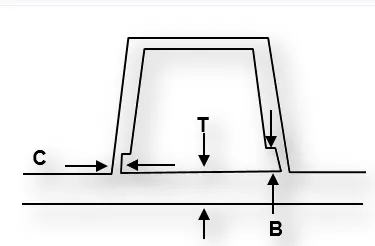
- Doghouse wall thickness at the intersection of the part wall ( C ) should be 40% or less than the main wall stock ( T ).
- The height of ( B ) should be between 3.0 – 6.0 mm
STEP 1:- EXAMINE THE GIVEN INPUT SURFACE
To determine whether the surface has any open borders, utilise the boundary feature. This allows us to determine whether there is an open patch of the surface that needs to be worked on.
1. BOTTLE HOLDER
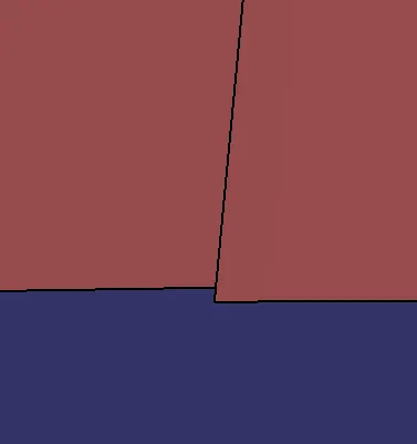
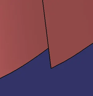
Check for open patches if they exist; in the instance of the bottle holder, the specific surface is causing an issue in the subsequent solid body formation.
 |
 |
| IMPROVEMENT NEEDED 1 | IMPROVEMENT NEEDED 2 |
2. LOWER SUBSTRATE
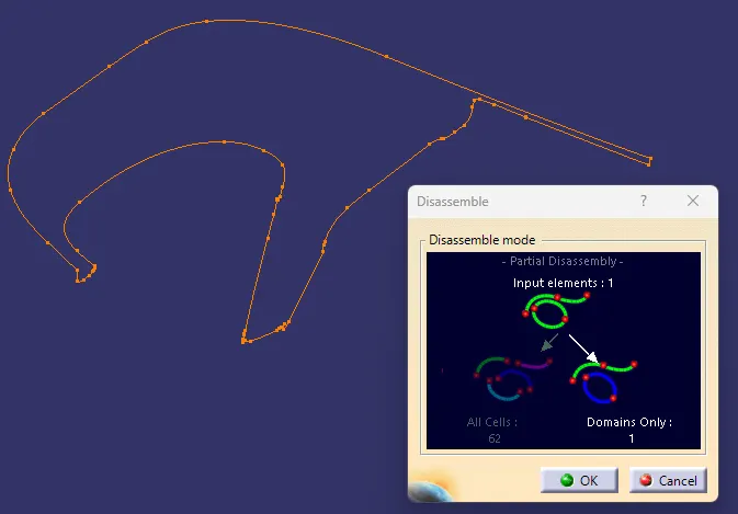
In the case of the lower substrate of the door, after reviewing the specified input surface. I found no flaws in the surface.
3. MAP POCKET
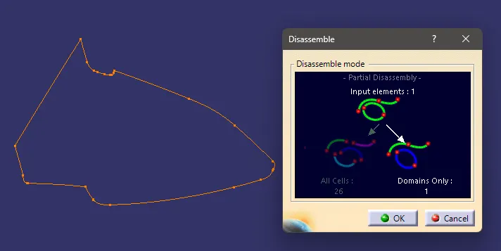
In the case of the Map Pocket of the door, after reviewing the specified input surface. I found no flaws in the surface.
4. ARM REST
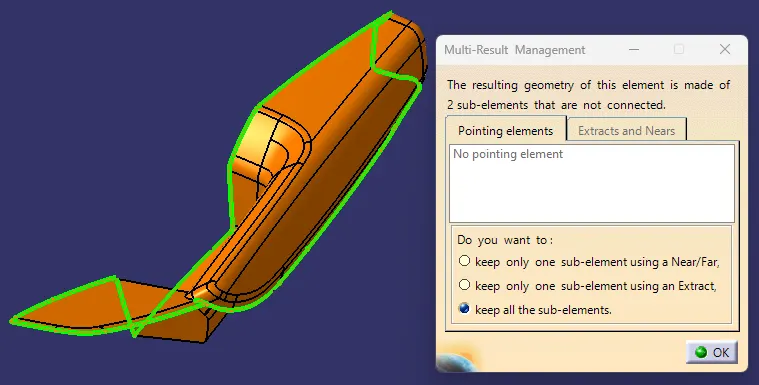
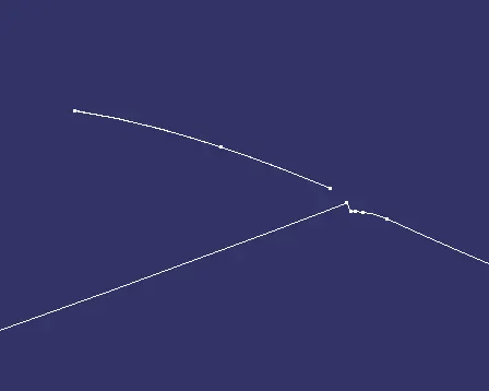
In the case of the Arm Rest of the door, after reviewing the specified input surface. I found a few flaws as shown below:-
STEP 2:- THE SURFACE OF CLASS A IMPROVISION
I found Bottle Holder and Arm Rest need improvement.
1. BOTTLE HOLDER
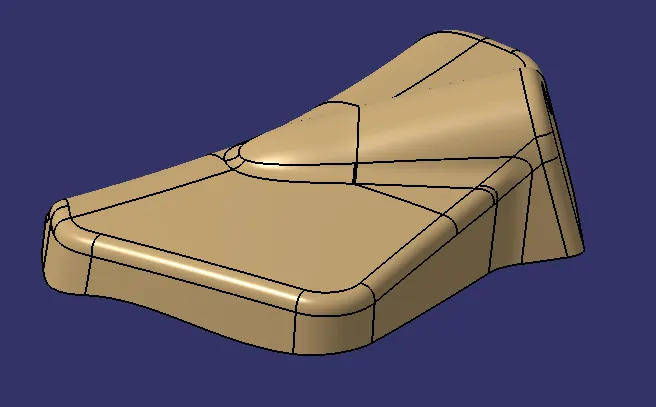
So, in this case, we use the join command and the sub-elements to remove the feature to remove the specific surface from the input one, and we utilise the multisection feature to complete the needed surface for class A.
2. ARM REST
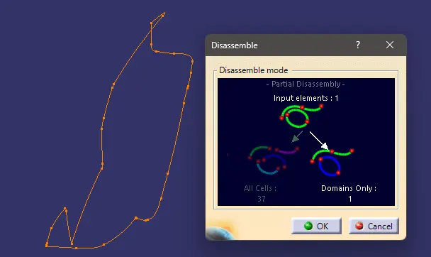
After you've finished working on the open patch, examine the surface's border to see any potential for open surfaces. The acquired surface is then designated as the class A surface, and work on it begins.
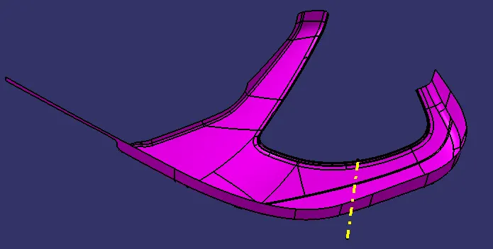
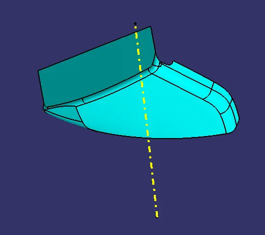
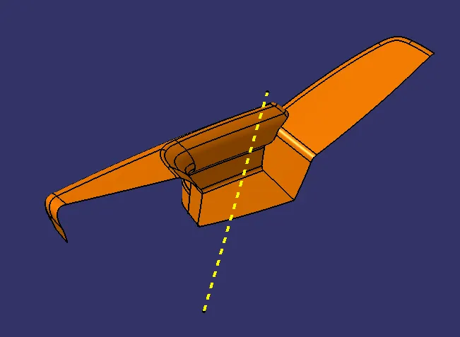
STEP 3:- CREATION OF TOOLING AXIS
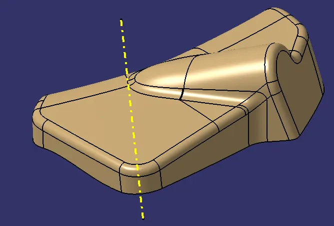
By observing the surface from different angles, you may extract the surface from Class A that is completely visible and easy to manufacture.
- Make a point in the centre now.
- At 0 coordinates, draw a line using the point and direction technique
- That line will serve as our primary tooling axis.
1. BOTTLE HOLDER
2. LOWER SUBSTRATE
3. MAP POCKET
4. ARM REST
STEP 4:- CLASS A SURFACE DRAFT ANALYSIS
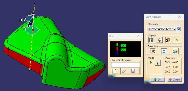
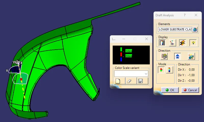
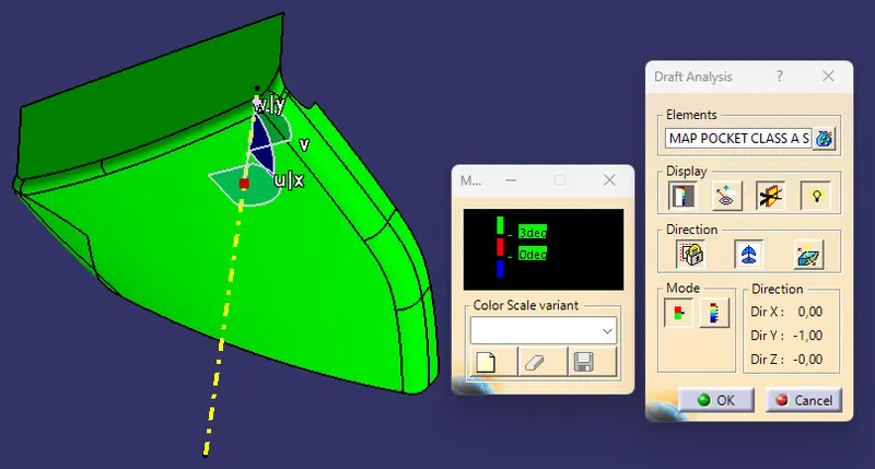
Once the tooling axis has been created, run a draft analysis of the class A surface to see if all of the surfaces of class A pass the draft analysis. The plastic engineering software provides a general draft angle of 3 degrees.
1. BOTTLE HOLDER
2. LOWER SUBSTRATE
3. MAP POCKET
4. ARM REST
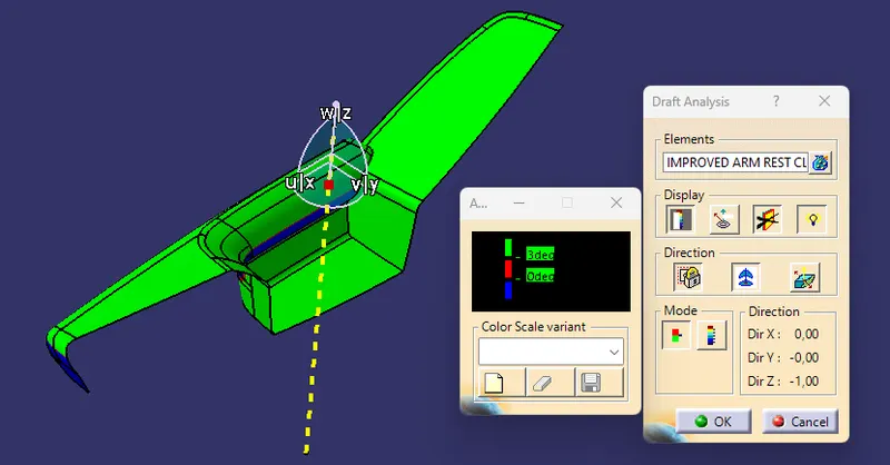
Some of the surfaces of the Class A Surface are unable to clear the draft analysis concerning the main tooling axis, thus you should either report to the relevant team to update the draft on the uncleared surfaces or continue it.
NOTE: A few portions do not pass the draft analysis. The mentor stated that it is a Class A flaw that can be carried forward. Please consider
STEP 5:- CREATION OF A CLASS B SURFACE
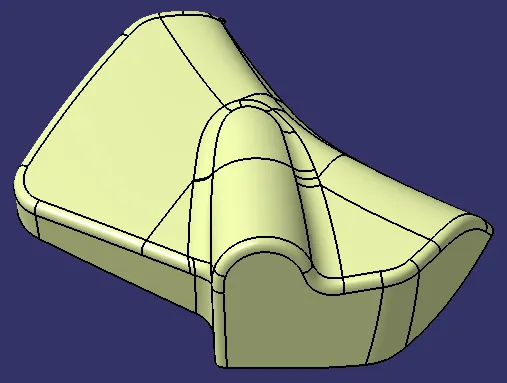
For the creation of the Class B Surface, refer to the master section given to measure the thickness of the plastic component, then offset the Class A surface to a depth of 2.5 mm under the Class A surface.
1. BOTTLE HOLDER
2. LOWER SUBSTRATE
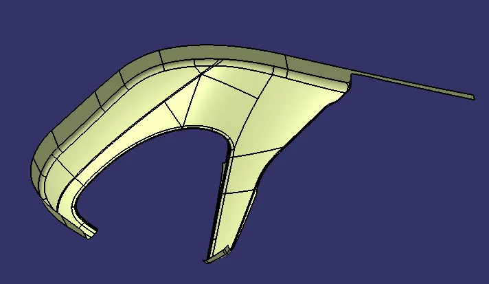
3. MAP POCKET
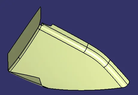
In this case, while offsetting the Class A surface found one error and improved by using Multisection, Spline, Join and Extract commands as below:-
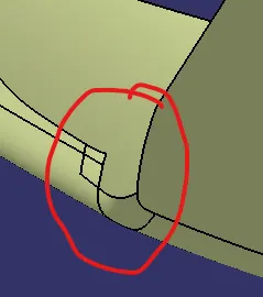 |
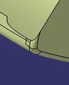 |
| OPEN PATCH | IMPROVED PATCH |
4. ARM REST
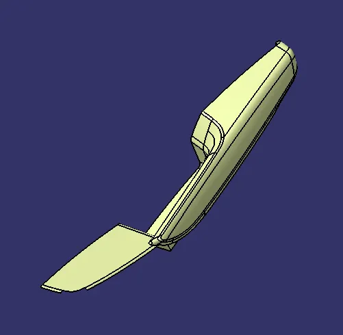
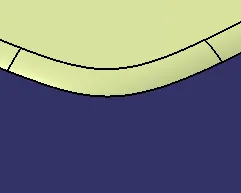
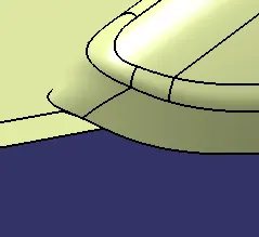
In this case, while offsetting the Class A surface found a few errors and improved by using Multisection, Split, Spline, Join and Extract commands as below:-
| Sr. No. | Error Found | Error Improved |
| 1. | 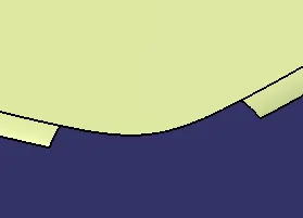 |
 |
| 2. | 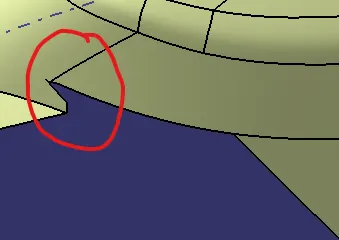 |
 |
STEP 6:- CREATION OF A CLASS C SURFACE
Create the Class C surface, which is an intermediate surface between the Class A and Class B surfaces, by using the sweep feature.
1. BOTTLE HOLDER
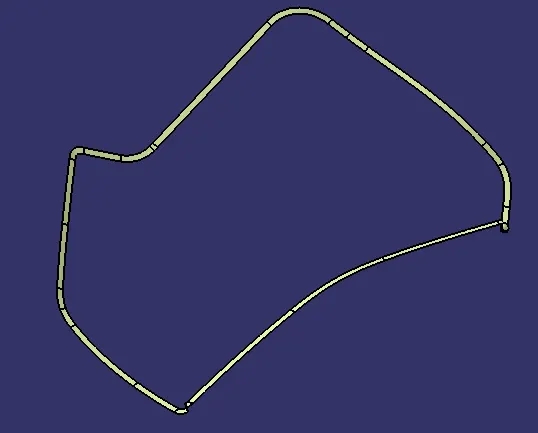
Now, using the class A surface, the sweep feature along the draft direction, and the reference surface characteristics, generate the class C surface. As a result, offer a draft of 3 degrees along the draft direction, with the draft direction serving as the primary tooling axis, and a draft of 90 degrees concerning the reference surface.
2. LOWER SUBSTRATE
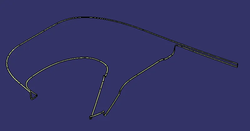
Use the sweep about the draft when the surface of Class C is parallel to the tooling axis. When seen from the normal direction about the main tooling axis, the surface must be outside the class A surface by 3 degrees. If the class C surface to be created is perpendicular to the tooling axis, then sweep with the reference surface. Using 90 degrees or 87 degrees
3. MAP POCKET
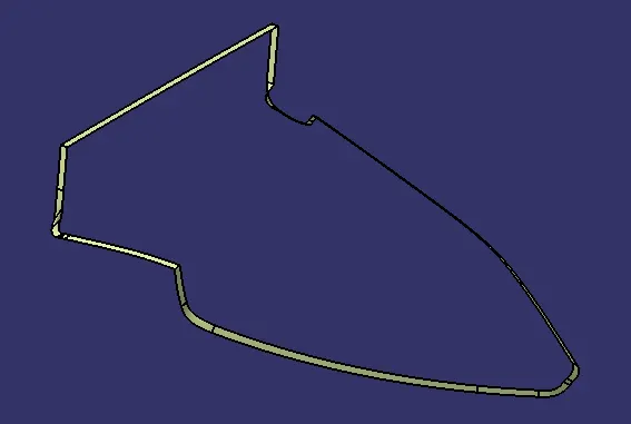
Create the class C surface, which is an intermediate surface between the class A and class B surfaces, by using the sweep feature with a draft of 3 degrees along the tooling axis direction and a draft of 90 degrees along the reference surface sweep.
4. ARM REST
We utilise the class A surface as a reference for the class C surface generation and follow the draft about the reference surface and the primary tooling axis.
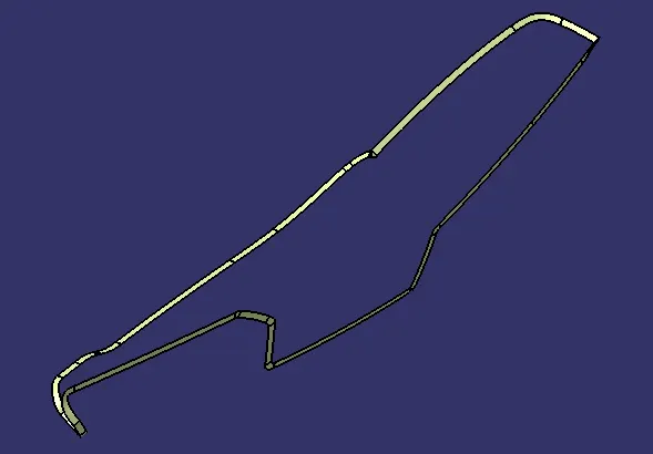
STEP 7:- CREATION OF A SOLID BODY
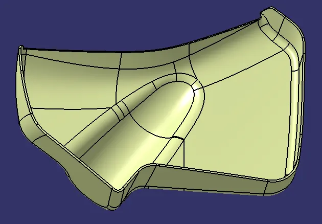
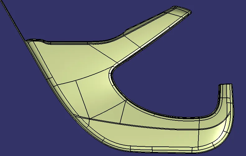
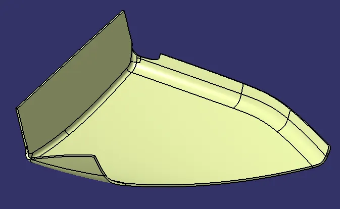
Once all of the surfaces, both Class B and Class C, have been formed, combine the Class A and Class C surfaces and trim the joining surface with the Class B surface to make the final closed surface.
1. BOTTLE HOLDER
2. LOWER SUBSTRATE
3. MAP POCKET
4. ARM REST
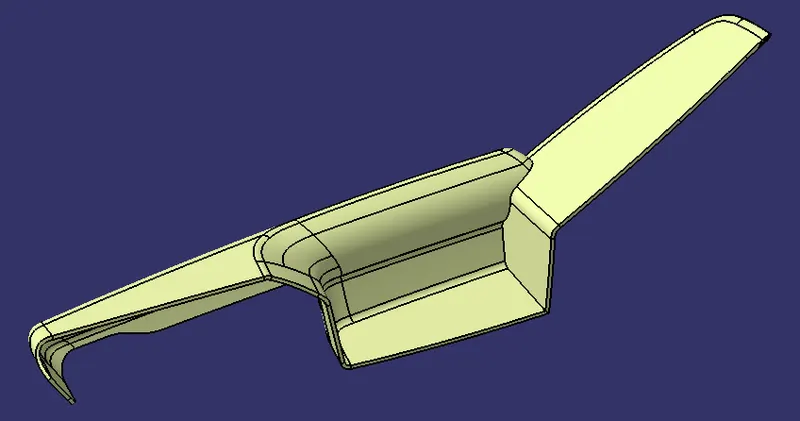
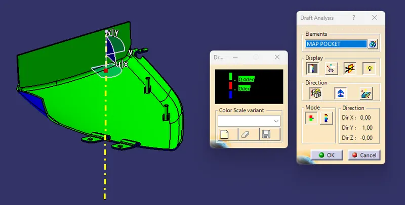
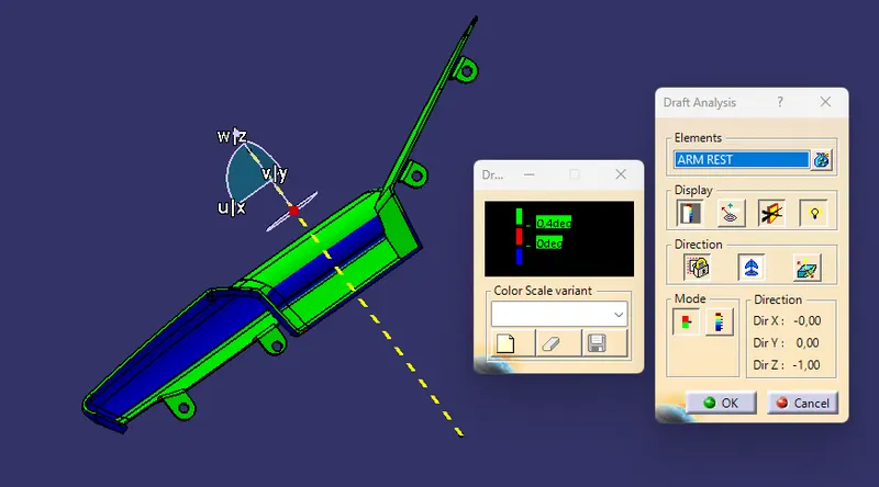
STEP 8:- DRAFT ANALYSIS OF THE SOLID BODY
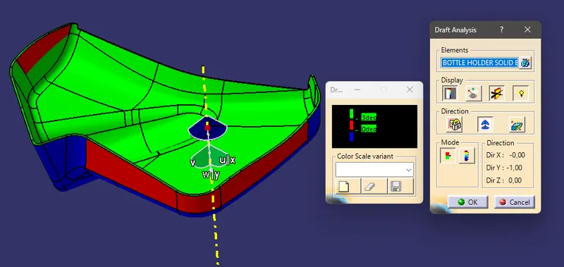
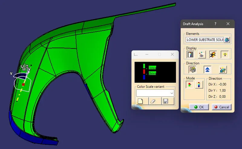
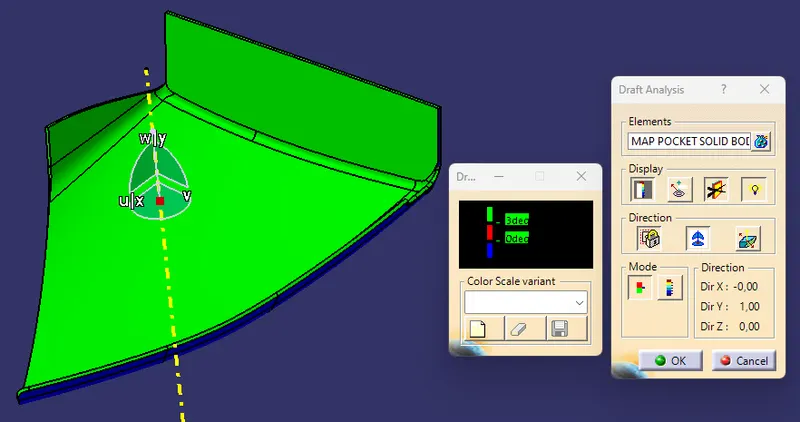
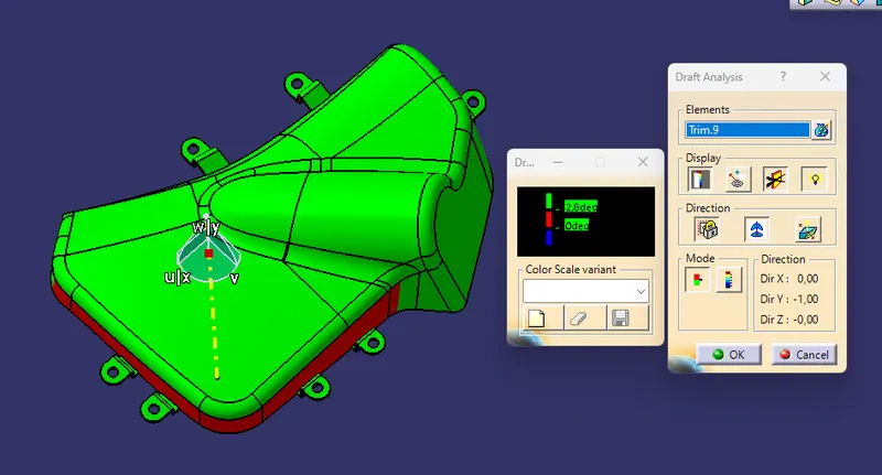
Perform the draft analysis with a draft angle of 3 degrees after constructing the final closed body.
Also, check to see whether all needed surfaces are clearing the draft about the main tooling axis of any draft applied surfaces that can't clear the draft analysis. Write a report in which you explain why the surfaces in the draft analysis are unclear and provide a remedy if necessary.
1. BOTTLE HOLDER
2. LOWER SUBSTRATE
3. MAP POCKET
4. ARM REST
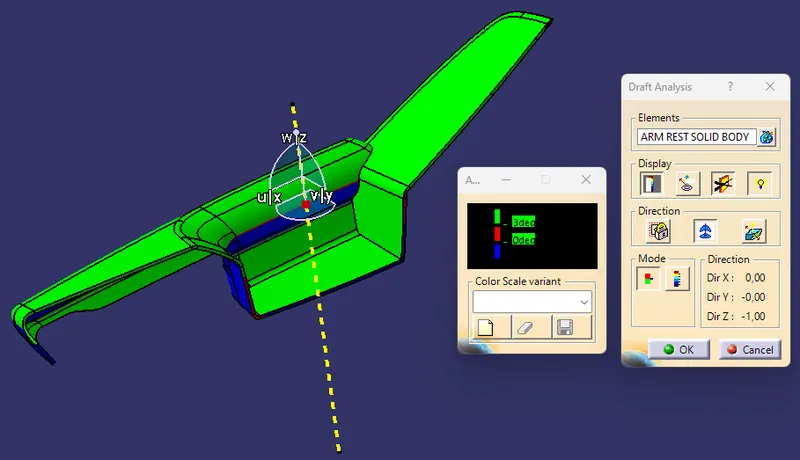
Many surfaces can clear the draft analysis, however, the surfaces mentioned in the Class A surface draft analysis have produced a problem when clearing the draft in the final solid surface.
In the case of class C surfaces, some of the surfaces have a lower draught or a negative draft because if they create the correct sweep followed, the quality of the surface obtained is not as good; it may be twisty or not uniform, so we continue with the negative draft.
STEP 9:- CREATION OF THE B-SIDE FEATURES
HEAT STAKES:-
Thermal staking, sometimes known as "heading or riveting," uses a controlled flow of molten plastic to grab or keep another component, often of a different material. When the two pieces are made of incompatible materials that cannot be welded or when simple mechanical retention of one component relative to another is sufficient, thermal staking is an alternative to welding.
The most prevalent use is the bonding of metal to plastic. A pre-moulded plastic boss is inserted into a hole in the metal portion. When the thermal tip makes contact with the boss, it generates localised heat.
As the boss melts, the horn's mild pressure develops a head in the shape dictated by the horn tip arrangement. When the heat is turned off, the plastic substance hardens and the dissimilar components get bonded.
So, taking references from the master section, keep in mind that whenever we take a reference from the master section, the referenced element should be isolated from the master section, so begin working on the heat stakes creation and provide support for it with ribs on all four sides to add additional strength to the heat stake.
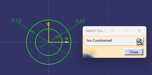
- We must adhere to the master section in terms of height.
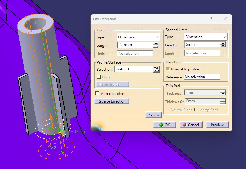
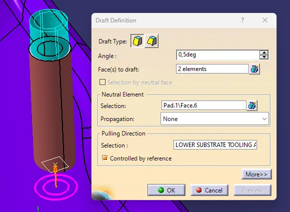
- A 0.5-degree draft is supplied on both the outer and inner faces.
- Pad the sketch with a height shown in the master section, using the tooling axis direction as a guide.
- Apply the 0.5-degree draft to both the inner and outer borders.
- Create the ribs for extra support now.
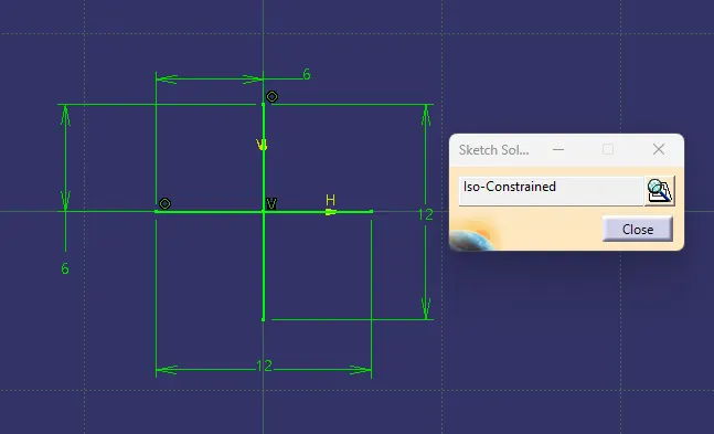
- Now, pad the sketch.
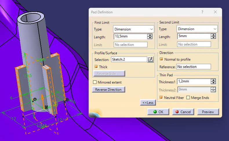
- The height is 13.5, and after giving the draft, the breadth at the top should be larger than or equal to 0.75 mm.
- The component thickness is 1mm, which is close to 50% of the component wall thickness = 50% of 2.5 = 1.25mm.
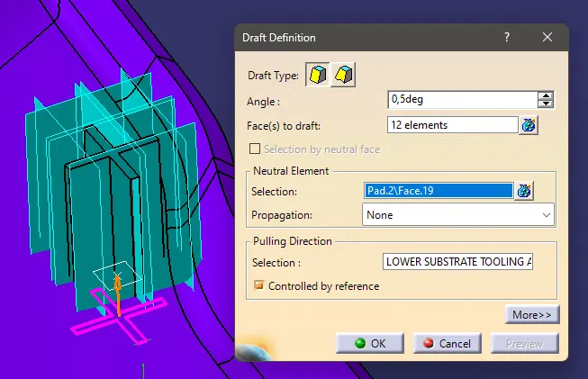
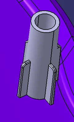
- Apply 0.25 mm fillets to all sharp edges, and you may also chamfer the tip of the ribs and use the boolean operation of union trim to connect the ribs with the heat stake.
- As a result, we must place the heat stakes all over the component, with the gap between the two heat stakes being 50-100 mm.
LOCATORS:-
Another attachment feature we make is a four-way locator because when there is a need for more heat stakes but the distance is insufficient to produce another heat stake due to design rules, we create the locators and the height of the locator must be higher than the heat stakes.
- During assembly, locators are utilised to locate the position of the mating part.
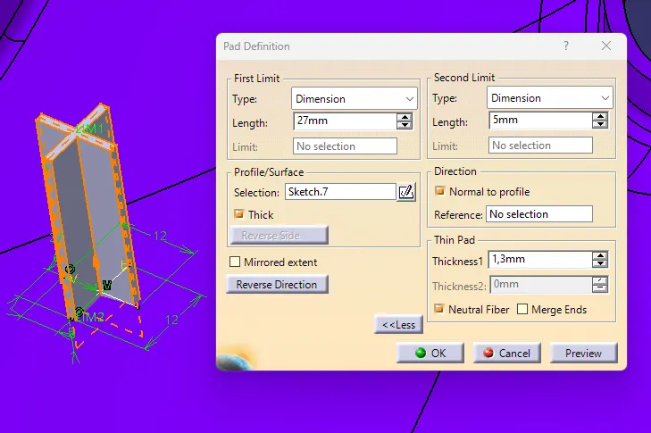
- The design guideline for the locator is largely the same as for the rib, except that the locator's height should be greater than the heat stakes by at least 5mm.
- The locator also limits the movement of the mating component.
- The distance between Flange and the locator should be between 0.5mm and 1mm.
- The design criteria are the same as in the case of ribs but with minor adjustments to the sketching.
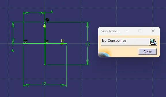
- The height should be bigger than the heat stake, and a draft of 0.5 degrees should be provided by using the neutral element as the sketch plane and the pulling direction as the primary tooling axis.
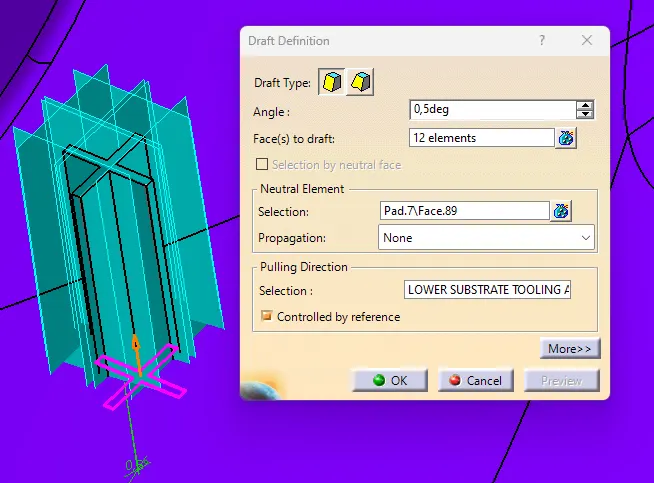
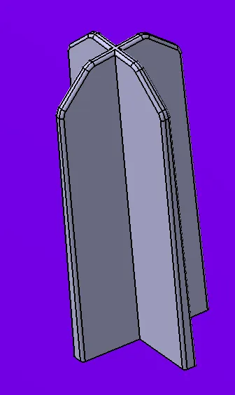
- The final attachment of the 4-way locator is made by applying a minimum fillet of 0.25 mm on all sharp corners and a chamfer of length and angle of 3 mm and 45 degrees at the top.
- The top locator's width must be more than or equal to 0.75mm.
DOG HOUSES:-
The doghouse is an engineering element utilised in the plastic trim design that aids in the removal of sink marks created on the Class-A surface while producing an attachment feature on the Class-B surface. Other elements such as locators, heat stakes, and pushpins are put on top of the doghouse for fastening and assembling purposes. Draft analysis is performed on doghouses to prevent component breakage during ejection from the mould.
- Create a point on the extracted line by using the middle point option in the point command.
- Create a line on the point and the line is called SIDE CORE TOOLING AXIS.
- Now, create a plane on the point.
- Draw a sketch by using the created plane and point.
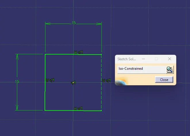 |
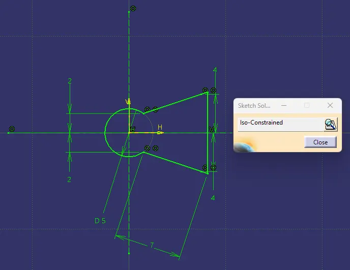 |
| SKETCH OF THE OUTER BODY OF THE DOG HOUSE | SKETCH OF TOP CUTOUT SECTION OF DOG HOUSE |
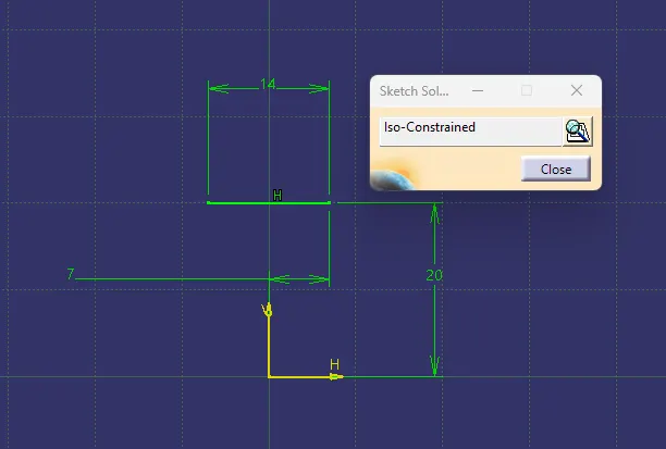 |
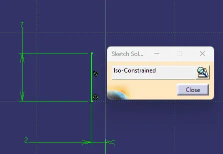 |
| SKETCH OF THE CONNECTOR | SKETCH OF THE RIBS |
- Now, extrude the sketch of the outer body of the dog house.
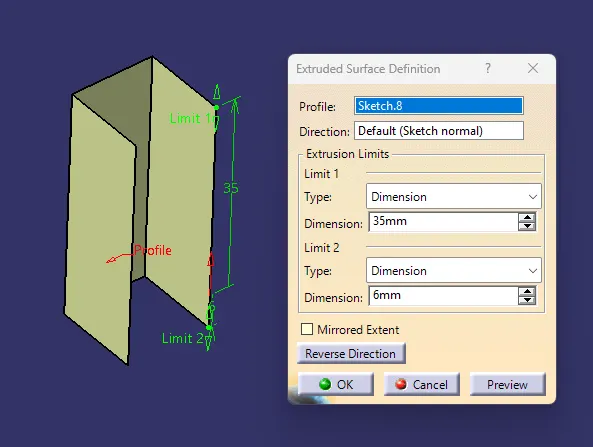
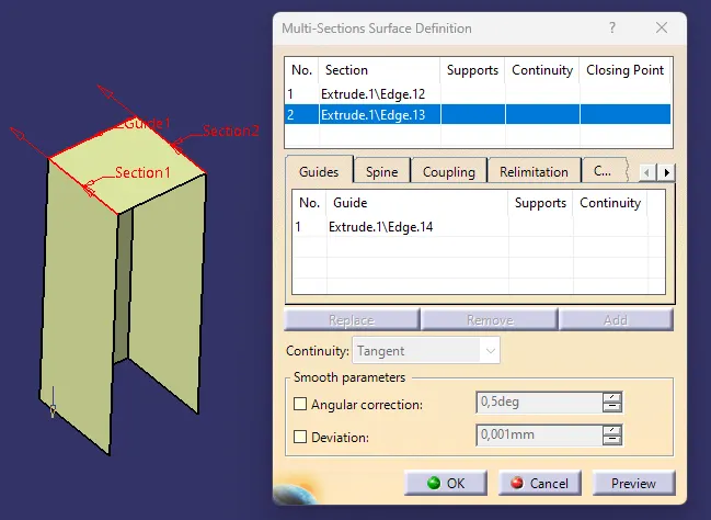
- By using the Multi-Section Surface command fill the surface of the dog house.
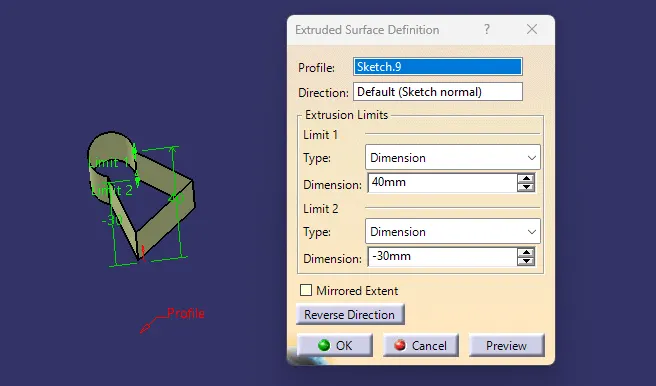
- Extrude the sketch of the dog house's top cutout section and cut the top surface by using the split command.
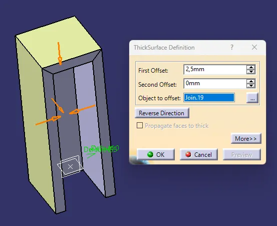
- Go to the Part Workbench to add a 2.5mm thickness and draft the outer surface with the tooling axis and the inner surface with the side core tooling axis about 0.5deg.
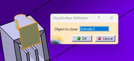
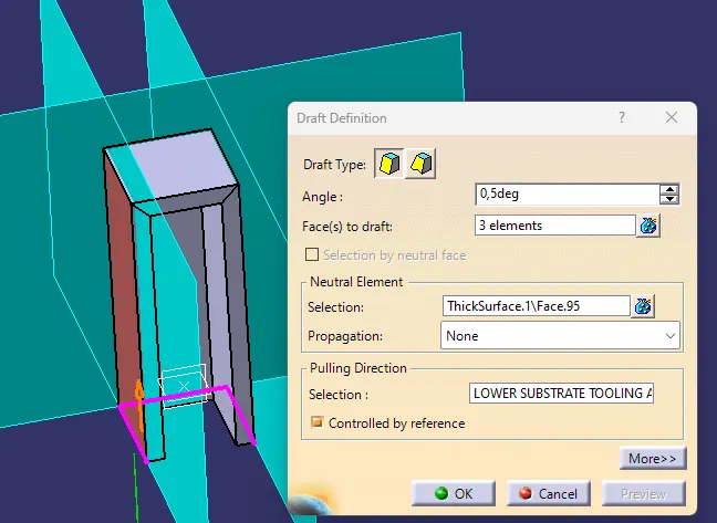
- Follow the same procedure for the connector and ribs.
- Apply the union trim command within the outer body, connector & ribs.
- Now, Extract the inner surface of the dog house and offset by 1 mm.
- Extrapolate the extracted surface and trim it with the offset surface of a solid body.
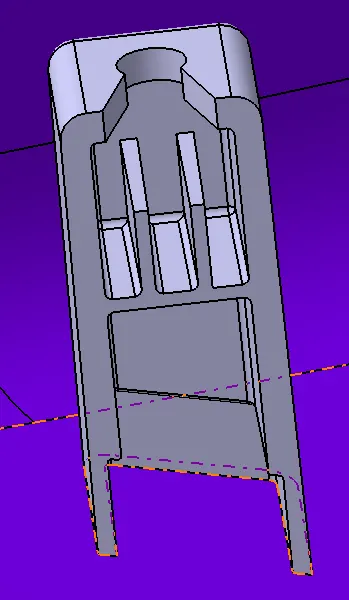
- Apply split command and remove the bottom portion of the dog house, give fillets to it and Union Trim with the solid body.
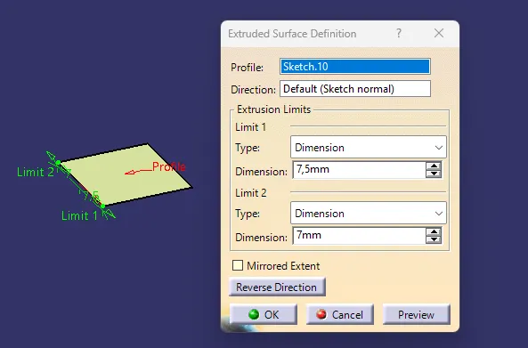
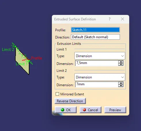
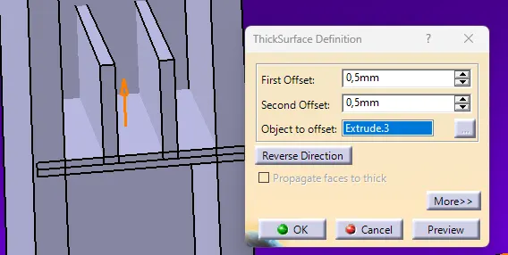
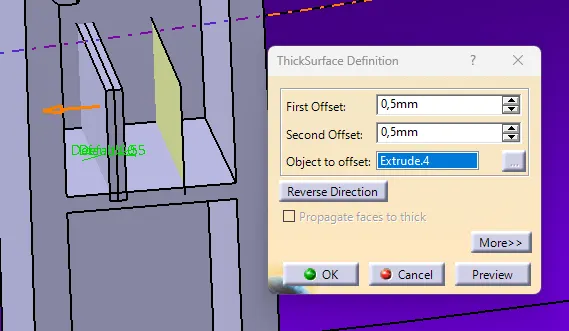
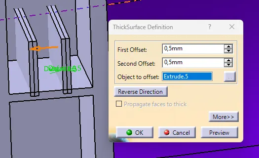
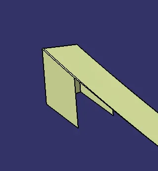
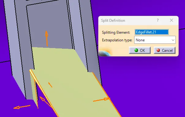
- Apply appropriate fillets and our dog house is ready.
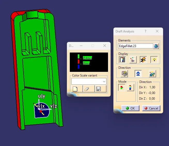
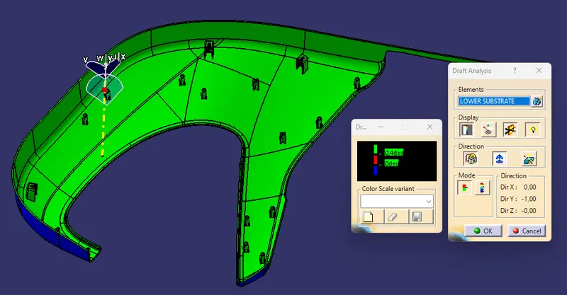
- Go for the draft analysis of the dog house with a side core axis (angle:- 0.4 deg).
So, on the lower substrate, we need to supply up to three dog houses while keeping in mind that there may be no engineering feature inside a direction of the slider movement of up to 90mm (minimum distance).
We utilise the point-to-point translation option to copy and paste the dog homes in various positions, and we use the rotate option to modify the direction of the slider opening.
PUSH PINS:-
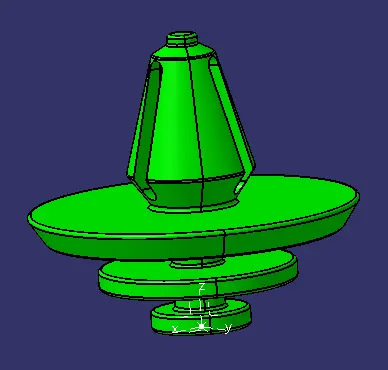
Push pins are used to connect two components. These are essentially connected to the doghouse. The dimensions for the push pins were acquired from the following reference.
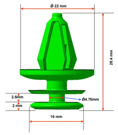
FLANGES:-
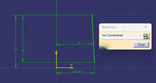
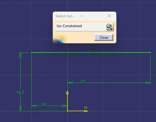
Flanges are connecting characteristics that aid in the assembly of various components. Flanges were created using the master section. After constructing one flange, the flanges are translated using point-to-point translation. For the flanges, we need to create a draft of 0.5 degrees. The distance between the flanges should be 50-100 mm. To add attachment characteristics to a closed body, Boolean operations were employed.
- The sketches were created using references from the master section.
- The flange's surface formed.
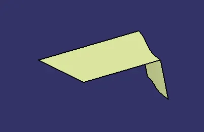
- Thicken the surface of the component workbench to 2.5mm thickness.
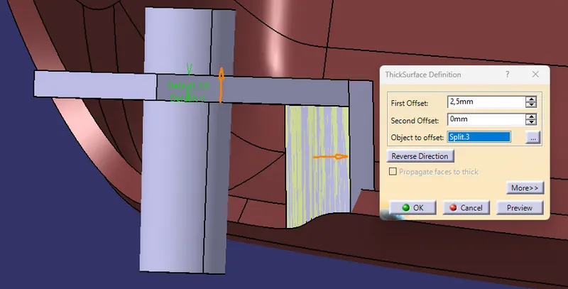
- The surface offset may be used to divide the uneven surfaces on the thickened surface.
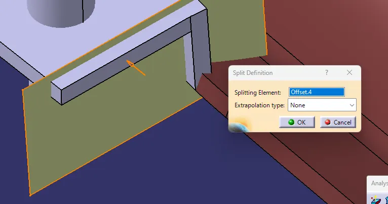
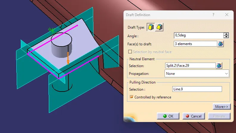
- Apply a 0.5-degree draft to the flange edges. Next, apply suitable fillets to the corner edges.
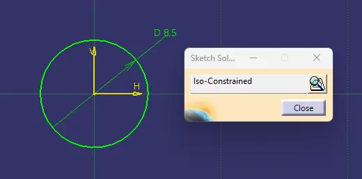
- Now drill a hole in the hole to properly locate the heat stake or locator about the flange.
- The hole diameter should provide for clearance of 0.5 to 1 mm between the flange and the heat stake or between the flange and the locator.
- Pad the sketch and use a draft angle of 0.5 degrees about the tooling axis.
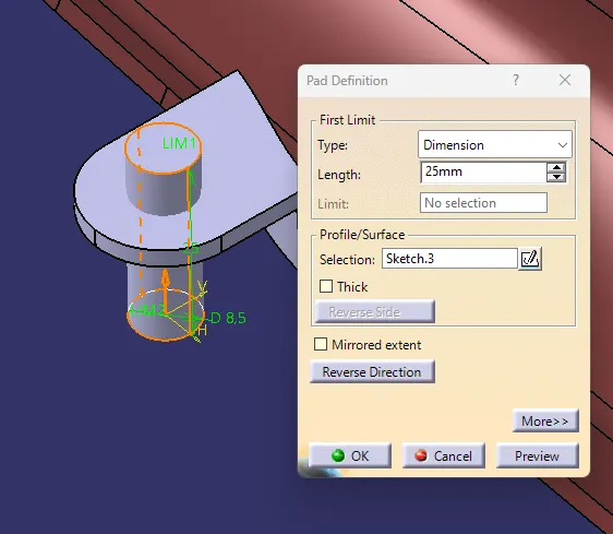
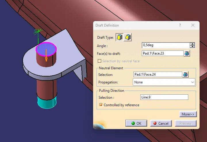
- Use the boolean operation to create the ideal hole on the flange and the resulting clearance.
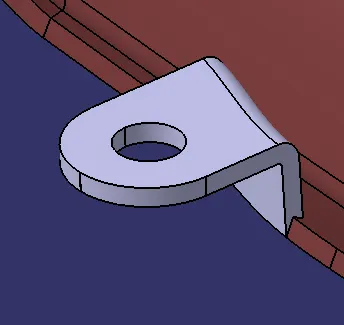
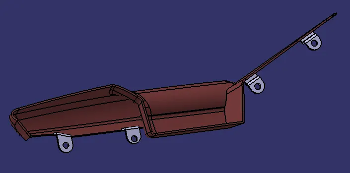
- As a result, we must create flanges at each point about the heat stakes, which are located on the bottom substrate for the assembly.
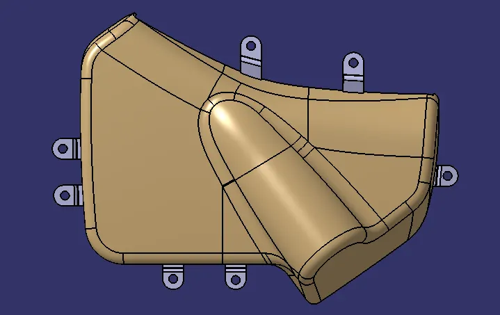
- The Bottle Holder master section is not provided. So, I used extracted the c surface and drew the sketch with particular to the heat stakes and flanges created below for the Map Pocket, Arem Rest and Bottle Holder.
 |
 |
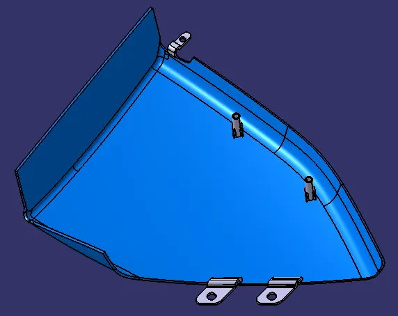 |
| ARMREST WITH B-SIDE FEATURES | BOTTLE HOLDER WITH B-SIDE FEATURES | MAP POCKET WITH B-SIDE FEATURES |
STEP 10:- DRAFT ANALYSIS OF THE SOLID BODY, INCLUDING B-SIDE CHARACTERISTICS
1. BOTTLE HOLDER
2. LOWER SUBSTRATE
3. MAP POCKET
4. ARM REST
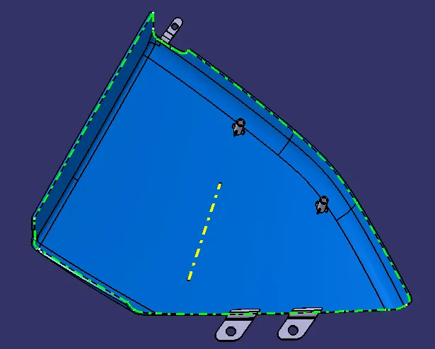
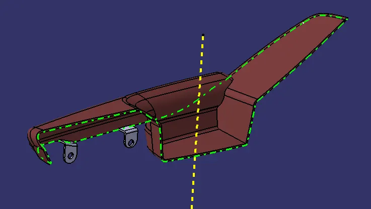
STEP 11:- CREATION OF PARTING LINE
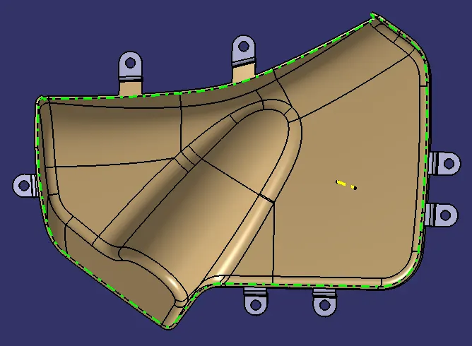
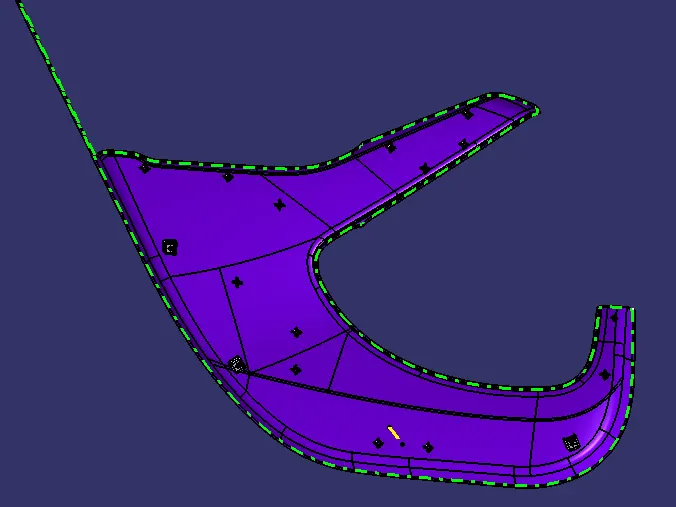
A parting line is the boundary line where draft angles change direction in industrial mould casting. The dividing line in the mould or product that divides the two halves, i.e. the core and the cavity of a moulded object, may be checked. It is occasionally used as a starting point for the mould parting surface.
1. BOTTLE HOLDER
2. LOWER SUBSTRATE
3. MAP POCKET
4. ARM REST
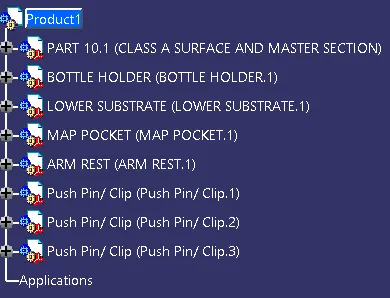
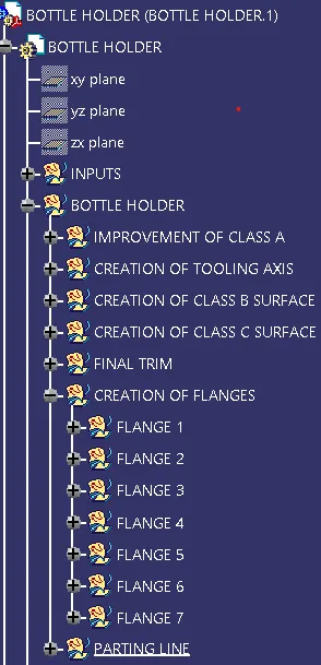
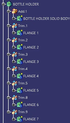
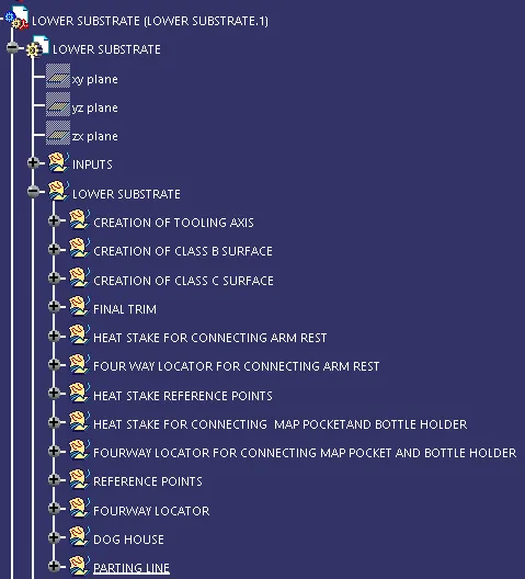
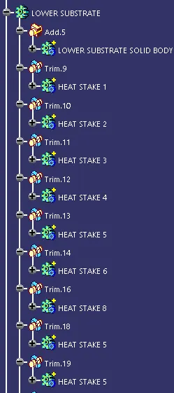
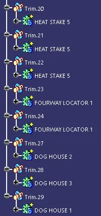
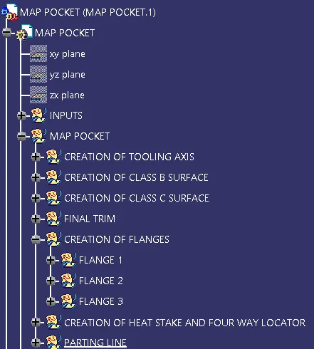
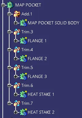
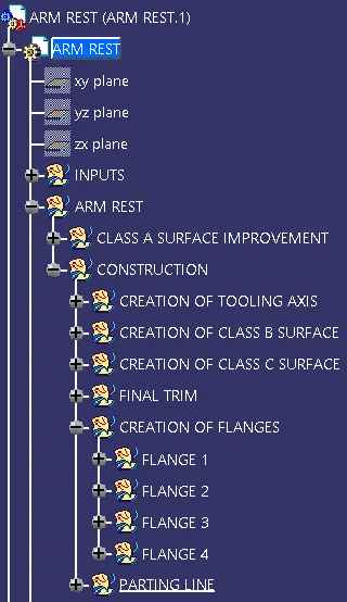
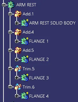
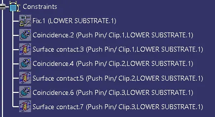
TREE STRUCTURE
SCREENSHOT OF THE DIFFERENT ORIENTATIONS OF THE FINAL BODY (ISOMETRIC, SIDE, TOP, FRONT)
FRONT VIEW
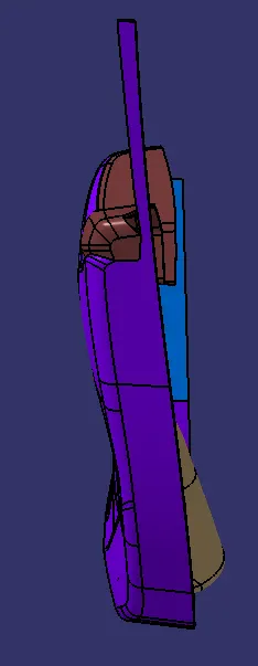
RIGHT HAND SIDE VIEW
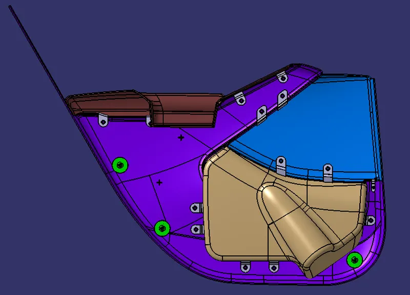
LEFT HAND SIDE VIEW
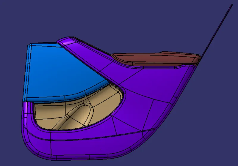
TOP VIEW
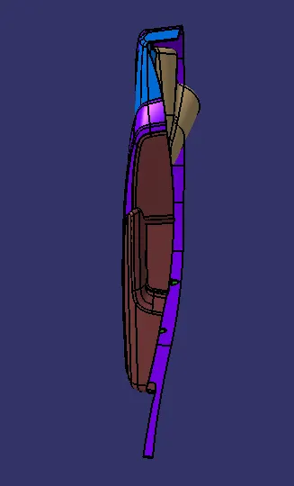
ISOMETRIC VIEW